1
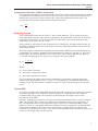
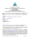
5686
Glass Capsule Standard Platinum Resistance Thermometer
Users Guide
2004, Rev. 1, 4/11
© 2004 - 2011 Fluke Corporation. All rights reserved. Specifications subject to change without notice.
All product names are trademarks of their respective companies.
Limited Warranty & Limitation of Liability
Each Fluke product is warranted to be free from defects in material and workmanship under normal use and service.
The warranty period is one year and begins on the date of shipment. Parts, product repairs, and services are warranted
for 90 days. This warranty extends only to the original buyer or end-user customer of a Fluke authorized reseller, and
does not apply to fuses, disposable batteries, or to any product which, in Fluke’s opinion, has been misused, altered,
neglected, contaminated, or damaged by accident or abnormal conditions of operation or handling. Fluke warrants
that software will operate substantially in accordance with its functional specifications for 90 days and that it has been
properly recorded on non-defective media. Fluke does not warrant that software will be error free or operate without
interruption.
Fluke authorized resellers shall extend this warranty on new and unused products to end-user customers only but have
no authority to extend a greater or different warranty on behalf of Fluke. Warranty support is available only if product
is purchased through a Fluke authorized sales outlet or Buyer has paid the applicable international price. Fluke reserves
the right to invoice Buyer for importation costs of repair/replacement parts when product purchased in one country is
submitted for repair in another country.
Fluke’s warranty obligation is limited, at Fluke’s option, to refund of the purchase price, free of charge repair, or
replacement of a defective product which is returned to a Fluke authorized service center within the warranty period.
To obtain warranty service, contact your nearest Fluke authorized service center to obtain return authorization
information, then send the product to that service center, with a description of the difficulty, postage and insurance
prepaid (FOB Destination). Fluke assumes no risk for damage in transit. Following warranty repair, the product will
be returned to Buyer, transportation prepaid (FOB Destination). If Fluke determines that failure was caused by neglect,
misuse, contamination, alteration, accident, or abnormal condition of operation or handling, including overvoltage
failures caused by use outside the product’s specified rating, or normal wear and tear of mechanical components, Fluke
will provide an estimate of repair costs and obtain authorization before commencing the work. Following repair, the
product will be returned to the Buyer transportation prepaid and the Buyer will be billed for the repair and return
transportation charges (FOB Shipping Point).
THIS WARRANTY IS BUYER’S SOLE AND EXCLUSIVE REMEDY AND IS IN LIEU OF ALL OTHER
WARRANTIES, EXPRESS OR IMPLIED, INCLUDING BUT NOT LIMITED TO ANY IMPLIED WARRANTY OF
MERCHANTABILITY OR FITNESS FOR A PARTICULAR PURPOSE. FLUKE SHALL NOT BE LIABLE FOR ANY
SPECIAL, INDIRECT, INCIDENTAL, OR CONSEQUENTIAL DAMAGES OR LOSSES, INCLUDING LOSS OF
DATA, ARISING FROM ANY CAUSE OR THEORY.
Since some countries or states do not allow limitation of the term of an implied warranty, or exclusion or limitation
of incidental or consequential damages, the limitations and exclusions of this warranty may not apply to every buyer.
If any provision of this Warranty is held invalid or unenforceable by a court or other decision-maker of competent
jurisdiction, such holding will not affect the validity or enforceability of any other provision.
Fluke Corporation
Fluke Europe B.V.
P.O. Box 9090
P.O. Box 1186
Everett, WA 98206-9090
5602 BD Eindhoven
U.S.A.The Netherlands
11/99
Table of Contents
Title
Page
Introduction..........................................................................................................................1
Before You Start...................................................................................................................1
Symbols Used..................................................................................................................1
Safety Information...........................................................................................................2
Application.......................................................................................................................3
Calibration.......................................................................................................................3
Recalibration....................................................................................................................3
Return Procedure.............................................................................................................3
Verifying Probe Accuracy................................................................................................3
How to Contact Fluke......................................................................................................4
Specifications.......................................................................................................................5
Construction.....................................................................................................................5
Installation...........................................................................................................................5
Environmental Issues.......................................................................................................5
Mounting..........................................................................................................................5
Electrical Circuit..............................................................................................................5
Care and Handling Guidelines.............................................................................................6
SPRT Care........................................................................................................................6
Handling Guidelines........................................................................................................6
Operation.............................................................................................................................6
General.............................................................................................................................6
Comparison Calibration of Other Instruments.................................................................6
Measuring Current...........................................................................................................7
Thermal EMF.......................................................................................................................7
i
5686
Users Guide
ii
List of Tables
Table
Page
Title
Table 1. International Electrical Symbols................................................................................................2
Table 2. Specifications.............................................................................................................................5
iii
5686
Users Guide
iv
List of Figures
Figure
Title
Page
Figure 1. 5686 Glass Capsule Standard Platinum Resistance Thermometer...........................................1
Figure 2. The construction of 5686 SPRT................................................................................................5
v
5686
Users Guide
vi
Introduction
The Fluke Calibration Glass Capsule Standard Platinum Resistance Thermometer (SPRT) is
designed to be the best primary standard interpolating instrument converting temperature to
resistance. The Fluke 5686 Glass Capsule SPRT is a member of the Fluke Calibration SPRT
family (Figure 1). The 5686 SPRT is primarily designed for the following two applications: used
in low temperature range down to 13 K (–260 °C), or used where a totally immersed probe is
prefered to minimize the heat flow from or to the sensor. Long stem SPRTs are not suitable for
some applications where the probe should be encased into a vessel completely. The 5686 SPRT
covers the range from 13 K (–260 °C) to 505 K (232 °C).
The 5686 is carefully annealed at the appropriate temperatures and precisely tested for stability.
The sensing elements are fabricated using high-purity platinum wire wound in a strain-free design
on a fused silica cross frame. The special glass capsule of the 5686 is pressure sealed with 5N
pure helium.
5686.tif
Figure 1. 5686 Glass Capsule Standard Platinum Resistance Thermometer
Before You Start
Symbols Used
Table 1 lists the International Electrical Symbols. Some or all of these symbols may be used on
the instrument or in this manual.
1
5686
Users Guide
Table 1. International Electrical Symbols
Symbol
Description
Symbol
Description
O
Off
I
On
X
Electric Shock
:
Hot Surface (Burn Hazard)
W
Read the User’s Manual
(Important Information)
I
B
D
AC (Alternating Current)
M
F
DC
)
Canadian Standards Association
T
Double Insulated
P
CE Complies with European Union
Directives
.
AC-DC
PE Ground
;
Fuse
Battery
C-TIC Australian EMC Mark
CAT II equipment is designed to
protect against transients from energyequipment supplied from
CAT II consuming
the fixed installation, such as TVs, PCs,
portible tools, and other household
appliances.
Safety Information
Use this instrument only as specified in this manual. Otherwise, the protection provided by the
instrument may be impaired.
The following definitions apply to the terms “Warning” and “Caution”.
• “Warning” identifies conditions and actions that may pose hazards to the user.
• “Caution” identifies conditions and actions that may damage the instrument being used.
Warning
To avoid personal injury, follow these guidelines.
• DO NOT use this instrument to measure the temperature of any hazardous
live component.
• DO NOT use this instrument for any application other than calibration work.
• DO NOT use this instrument in environments other than those listed in the
user’s guide.
• Use of this instrument at high temperatures for extended periods of time can
cause the handle to become hot.
• Follow all safety guidelines listed in the Users Guide.
• Calibration equipment should only be used by trained personnel.
2
Glass Capsule Standard Platinum Resistance Thermometer
Before You Start
Caution
To avoid possible damage to the instrument, follow these guidelines.
• DO NOT remove the label from the handle. The delicate nature of the
instrument is described on the label.
• Read “Care and Handling Guidelines” before removing the SPRT from the
shipping box or case. Incorrect handling can damage the SPRT and void the
warranty.
• DO NOT subject the thermometer to any physical shock or vibration.
• Keep the shipping container in case it is necessary to ship the SPRT.
Incorrect packaging of the SPRT for shipment can cause irreparable damage.
• DO NOT subject the thermometer to temperatures above the highest
specified operating temperature.
• DO NOT expose the thermometer’s handle or cables to extreme
temperatures.
• DO NOT submerge the handle or cable in liquids.
Application
The 5686 thermometer is classified as a primary standard. A primary standard is defined in
terms of transfer of the ITS-90 from a standards laboratory to a customer’s laboratory. Primary
standards are calibrated in a standards lab using known intrinsic values. The SPRTs are designed
to meet the National Voluntary Laboratory Accreditation’s (NVLAP) Level I Accuracy Class.
Calibration
In order for any instrument to be used as a standard it must be calibrated. The SPRT may be
purchased calibrated or non-calibrated. Fluke Calibration has the capability of performing fixed
point calibration, or comparison calibrations traceable to NIST.
Recalibration
The recalibration of the SPRT should be scheduled according to the user’s company Quality
Assurance requirements. Normally, an SPRT is recalibrated annually. Fluke Calibration has the
capability of performing fixed point calibration, or comparison calibrations traceable to NIST.
Return Procedure
Not
Call the nearest Authorized Service Center for assistance before shipping.
Extreme care must be taken in shipping an SPRT. Place the thermometer in the factory provided
protective storage case. Be sure the case is latched securely. Place the protective case in the
original manufacturer’s wooden shipping crate or wooden crate with similar dimensions. Place
soft insulation on all sides of the crate to cushion the SPRT against mechanical shocks. The cover
of the crate should be attached with screws. We recommend that you label the crate as extremely
fragile. Whether the thermometer is returned for repair or warranty, please include a letter
containing the following information:
• Description of the faulty operation and circumstances of failure.
• Complete shipping instructions for the return of the thermometer to the customer.
3
5686
Users Guide
Verifying Probe Accuracy
Before using your probe, verify that its behavior has not changed significantly from the most
recent calibration (as can sometimes occur from mechanical shock during shipping, for example).
To verify your probe, check the probe at the Triple Point of Water (TPW) (0.01 °C) or in a wellconstructed ice bath, by following these steps:
1.Connect the probe to a calibrated readout and verify that the probe’s coefficients have been
correctly entered into the readout.
2.Properly prepare a TPW cell or ice bath. Contact Fluke Calibration for assistance. A TPW cell
is preferred. Ice baths should use distilled water and crushed ice in a Dewar flask or thermos
bottle. The ratio of ice-to-water should be such that the mixture is firm after prepared.
3.Set your readout to read in ohms rather than temperature. Place your probe in the TPW or ice
bath and allow it to stabilize. (Remember a TPW is at 0.01 °C and an ice bath is at 0 °C.)
4.If using a TPW cell, compare the resistance value on your readout with the resistance value
at TPW given on the probe’s certificate. If using an ice bath, compare the resistance value on
your readout with the resistance indicated on the certificate for 0 °C. (You may have to use
the probe’s temperature versus resistance table and interpolate to get the probe’s calibrated
resistance value at 0 °C.)
5.Considering the probe’s uncertainty specification, determine whether or not it is within
tolerance of the data on its most recent certificate of calibration. If it is, it may be placed in
service. If not, double-check the probe coefficients in the readout. If they are correct, contact
Fluke Calibration.
Fluke Calibration recommends that a probe be periodically checked against a standard such as
a TPW cell (or well-constructed ice bath if an ITS-90 fixed-point standard is not available). The
verification interval depends on how the probe is handled, how and how much it is used, and your
documented experience with it. Your probe should also be checked any time you suspect it may
have received mechanical shock or whenever its accuracy appears suspect.
How to Contact Fluke
To contact Fluke, call one of the following telephone numbers:
• Technical Support USA: 1-800-44-FLUKE (1-800-443-5853)
• Calibration/Repair USA: 1-888-99-FLUKE (1-888-993-5853)
• Canada: 1-800-36-FLUKE (1-800-363-5853)
• Europe: +31 402-675-200
• Japan: +81-3-3434-0181
• Singapore: +65-738-5655
• Anywhere in the world: +1-425-446-5500
Or, visit Fluke’s website at www.fluke.com.
To register your product, visit http://register.fluke.com.
To see, print, or download the latest manual supplement, visit
http://us.fluke.com/usen/support/manuals.
4
Glass Capsule Standard Platinum Resistance Thermometer
Specifications
Specifications
Table 2. Specifications
5686 Specifications
Temperature range
–260 °C to 232 °C
Nominal Rtp
25.5 Ω
Resistance ratio
W(302.9146 K) ≥1.11807, W(234.3156 K) ≤0.844235
Drift rate over the entire range
<0.005 °C per year
Drift rate over a range of 100 °C
Typically 0.001 °C per year
Filling gas
Pure helium (99.999 %)
Lead wires
Four platinum wires, 3 cm long
Diameter (mm)
5.5 ±0.3
Length (mm)
56
Construction
Construction of the 5686 SPRT is shown in Figure 2. The 5686 covers the range from 13 K to
505 K. The 25.5 Ω sensor element is crafted using high purity platinum wire wound in a strain
free design on a fused silica cross frame.
Glass Sheath
Sensor Support
Glass-Platinum Seal
Platinum Helix
Platinum Lead Wires
5686.eps
Figure 2. The construction of 5686 SPRT
Installation
Environmental Issues
Primary standard equipment should be used in a calibration laboratory or other facility
specifically designed for this purpose. Environmental requirements include:
•
•
•
•
Stable temperature and humidity
Clean, draft-free area
Low noise level: low radio frequency, magnetic or electrical interference
Low vibration levels
Mounting
Capsule-type SPRTs are usually used “totally immersed”, meaning that they are generally inserted
into a well in a copper block. The connections are made to long fine copper wires insulated with
varnish or a similar coating, and these are thermally anchored to the block and to at least one
other point within the cryostat so as to reduce or eliminate heat flow into or from the thermometer.
For applications above 100 °C, the user should decide how to mount the capsule in his apparatus
according to the conditions.
Electrical Circuit
The 5686 SPRT is equipped with four platinum wires with Teflon sleeves. Four lead wires are
used to cancel lead wire resistance. For best results, the readout device should be equipped to
handle four-terminal resistors. The lead wire colors are red and black. Two red color leads are
from one end of the sensor resistance, and two black leads are from another end (See Figure 2).
5
5686
Users Guide
Care and Handling Guidelines
Caution
Read before removing the SPRT from the case.
SPRT Care
The 5686 capsule Standard Platinum Resistance Thermometer (SPRT) is an extremely delicate
instrument. Great care must be taken in handling the SPRT to maintain calibration accuracy.
Vibration or shock may cause the resistance to increase. A slight tap to the SPRT tip can cause a
change in Rtpw as high as 1 mK. The glass capsule should always be wiped down with 200 proof
Ethyl Alcohol or other suitable solvent before exposure to high temperatures. Correct handling
of the SPRT will prolong the life expectancy. When not in use, the SPRT should be stored in the
protective case provided by Fluke.
Handling Guidelines
• Keep the thermometer as clean as possible. Always remove any fluid from the sheath
immediately after taking the thermometer from a bath. To remove any possible contaminants,
always wipe the sheath with Ethyl Alcohol or other solvent before submitting the SPRT to high
temperatures.
• Immerse the thermometer in the appropriate liquid for the temperature range. If a dry block is
used, the well diameter should allow the SPRT to comfortably slip in and out without excess
movement. For best results, immerse the thermometer as deep as possible to avoid “stem
effect” (the temperature error caused by the conduction of heat away from the sensor). Do not
submerge the handles.
• Allow sufficient time for the thermometer to stabilize before making measurements. This
allows for the best accuracy.
• Use the correct drive current with the thermometer to prevent error in temperature or
resistance.
• Anneal the thermometer at a temperature slightly higher than the maximum temperature at
which the thermometer will be used when it has been subjected to mechanical or temperature
shock. The SPRT should also be annealed before calibration. If the thermometer is annealed in
a furnace above 660 °C, the furnace should be base metal free.
• Use the protective case provided or other protection when the thermometer is not in use.
• DO NOT subject the thermometer to any physical shock or vibration.
• DO NOT subject the thermometer to temperatures above the highest specified operating
temperature.
• DO NOT expose the thermometer’s cables to extreme temperatures.
Operation
General
For best results, be familiar with the operation of the cryostat, calibration bath or furnace and the
read-out instrument. Be sure to follow the manufacturer’s instructions for the read-out instrument,
cryostat, and the calibration bath or furnace.
6
Glass Capsule Standard Platinum Resistance Thermometer
Operation
Comparison Calibration of Other Instruments
The uniformity and stability of the bath and the degree of accuracy required determine the number
of temperature measurements necessary. However, to follow “good” practice procedures, always
measure the triple point of water resistance (Rtpw) after each temperature measurement. This
provides the most accurate measurement of the resistance ratio:
W(t) = R(t)
Rtpw
Measuring Current
The recommended current for the 5686 is 1 mA for most situations. The resistance sensitivity
with temperature becomes lower at lower temperatures. To compensate for the loss of sensitivity,
measuring currents below 24.5 K are generally increased from 1 mA usually used above that
temperature, up to about 5 mA at 13.8 K.
Errors caused by self-heating of the element need to be minimized. Allowing sufficient time for
the SPRT to stabilize and the heat to be dispersed into the surrounding medium will provide the
most accurate results.
The Fluke testing or calibration certificates provided with the SPRT represent data that has been
extrapolated. For example, on Model 5686 measurements are made at 1 mA and 1.41 mA. These
measurements are then extrapolated to zero current. This can be done graphically by plotting
i² vs R and extrapolating to zero power or by using the following equation:
R0=R1 -
i12 (R2 - R1)
i22 - i12
Where:
R0 = Zero current resistance
R1 = Resistance measured at current i1
R2 = Resistance measured at current i2
The exact immersion depth required can be determined by performing a gradient test taking
measurements approximately every 1/2 inch (1.27 cm) until there is a significant difference in
readings. Allow the thermometer to stabilize at each new depth. Plot the results to see the stem
effect.
Thermal EMF
Two factors contribute to thermal EMF, chemical consistency and physical consistency. Variations
in chemical structure due to impurities and discrepancies in crystal structure can contribute
to thermal EMF. These factors are minimized by annealing the full length of wire before
construction of the SPRT.
Likewise, connection to extension lead wires and readout instruments can be a source of thermal
EMF. The thermal EMF is caused by a difference in temperature between two connections. If
the two connections are the same temperature, there will be little or no thermal EMF effects.
However, if there is a substantial temperature difference between connections, the thermal EMF
effects will be significant. Therefore, cover or insulate any exposed bridge or galvanometer
terminals to lessen the source of error. The effects of thermal EMF can be canceled by using an ac
bridge or a dc bridge with reversible current.
7
5686
Users Guide
8