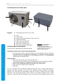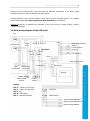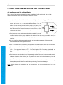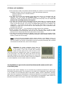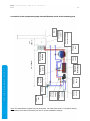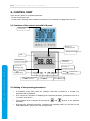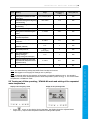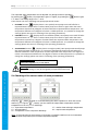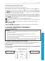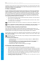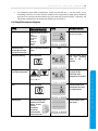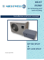
1
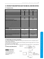
HEAT PUMP for swimming pool water heating Installation and user manual HP 900 SPLIT & HP 1200 SPLIT Version: April 2014 2|Installation and user manual CONTENTS 1. Introduction 1.1 How to use the heat pump 1.2 Heat pump operation 1.3 Package checking 4 3. Product description and technical specification 5 Technical data Swimming pool water parameters Heat pump dimensions Description of the basic parts Safety and control systems Block wiring diagram of the PCB board 4. Heat pump installation and connection 4.1 Positioning and air unit installation 4.2 Water unit installation 4.3 Installation of gas circuit connections between the water and air unit of the heat pump 4.4 Electric connection 4.4.1 Connection to the plug adapter 4.4.2 Fixed electric connection 5. Control unit HP SPLIT 3 3 3 2. Safety measures 3.1 3.2 3.3 3.4 3.5 3.6 HEAT PUMP MICROWELL 3 5.1 5.2 5.3 5.4 5.5 5.6 Functions of the control unit with LCD panel Setting of the operating parameters Mode selection and setting of the requested water temperature Checking of the current values of some parameters Timer setting Control panel lock 6. Use and operation of the device 6.1 Operating instructions 6.2 Setting of the operating status by the by-pass 6.3 Water condensation 6.4 Possible problems caused by external factors 6.5 Comments on the heat pump operation 6.6 Simplified control diagram 7. Maintenance and checking of the device 7.1 7.2 7.3 7.4 Maintenance Getting prepared for winter time Warranty conditions, service and spare parts Failure reports and their elimination 5 5 5 6 6 7 8 8 9 9 11 11 11 12 12 12 13 14 15 15 15 15 15 15 16 16 17 18 18 18 19 19 Installation and user manual |3 1. INTRODUCTION Thank you for purchasing our heat pump. The heat pump is manufactured in accordance with the related strict standards and norms, in order to provide high quality operation and reliability to our customers. This manual contains all the necessary information about the installation, operation and maintenance of the heat pump. Please read this manual carefully before starting to use the product. The manufacturer is not liable for any personal or property damage due to the improper installation, use or maintenance of the heat pump. The manual is an inseparable part of the product; therefore it must be kept in good conditions and must accompany the heat pump. 1.1 How to use the heat pump The heat pump is designed exclusively for heating the swimming pool water and keeping its temperature on the requested level economically. Any other form of application is considered inappropriate. The heat pump achieves the highest efficiency at 15÷25°C air temperature. At the temperature lower than +5°C the efficiency of the device is low and at the temperature higher than +40°C, it can get overheated. Heat pump could be used at air temperatures down to -10°C with water unit placed in nonfreezing environment. Efficiency of such usage however decreases rapidly. The product is designed for swimming pools with up to 40 m3 - HP 900 and up to 60 m3 - HP 1200. For proper operations, there must be a water flow through the heat pump exchanger in range of 4-6 m3/hour. By choosing the heat pump mode, it is possible to reverse the direction of the circulation in order to cool the swimming pool water. 1.3 Package checking The device is delivered in two individual parts, i.e. the air and the water unit. Water unit is prepared for connection to the piping distribution of the swimming pool filtration. The air unit is ready for connection to the water unit. Professional installation is required by a person or company authorized to install gas circuits with refrigerants. Please check whether the arrangement is complete, before any further manipulation with the device. Note: The illustrations and descriptions found in this manual are not binding. The manufacturer reserves the right to make corrections or changes without any liability to update this manual. EU symbol for waste sorting Save the environment. Keep the local regulations on waste disposal. Deliver any unused or faulty electric device for disposal to the professional institution in charge. HEAT PUMP MICROWELL The heat pump enables heat gain from the external air surrounding the swimming pool, through the compression – expansion cycles of the heat-carrying liquid. The air is driven by a fan through the evaporator, where it will deliver its heat to the heat-carrying liquid (the air is being cooled at the same time). The heat-carrying liquid is then delivered to the spirals of the exchanger by the compressor, which presses and heats it up. In these spirals, the heat-carrying liquid delivers its heat to the swimming pool water. From the exchanger there is a cooled liquid flowing to the expansion valve, where its pressure decreases and it gets cooled down rapidly at the same time. This cooled down liquid flows to the evaporator again, where it gets heated by the flowing air. The whole process runs smoothly and is monitored by the pressure and temperature sensors. HP SPLIT 1.2 Heat pump operation 4|Installation and user manual 2. SAFETY MEASURES WARNING: The unit contains electrical parts supplied with power. Only authorized person with particular electro technical qualification can manipulate unit unit. Danger of electrical shock. a) The positioning of the heat pump must be in accordance with the STN 33 2000-7-702 standard, i.e. it must be placed at least 3,5 m from the swimming pool´s external border. b) The connecting circuit of the heat pump must be in accordance with the related standard (STN 33 2000), must be equipped with a current protector with a 30mA interrupting current. c) Any kind of interference with the electric installation of the heat pump and with the feed circuit must be performed only by a specialized technician. d) Do not install the heat pump at places that can get flooded by water. e) Make sure that children are kept away from the working area of the heat pump. The main heat pump switch must be placed beyond the reach of children. f) Do not leave the heat pump in operation without a complete arrangement, including the covers. Rotating fans may cause serious injuries. The internal pipe is warm during operation and may cause burns when touched. HEAT PUMP MICROWELL HP SPLIT g) If you notice any damage on the flexible cord of the heat pump or on the extension cord on the inlet, turn off the circuit-breaker of the heat pump´s feed circuit immediately and eliminate the failure. h) Any kind of repair of the heat pump or interference with the pressure cooling circuit, must be performed only by a specialized technician. i) The product maintenance and operation must be performed in accordance with this user manual, in the recommended terms and frequency. j) Make sure that you use only original spare parts. In case of not following and keeping the above instructions, the warranty is not applicable. The cooling circuit is filled with R410A refrigerant that consists of 2 components (R32/R125). These components are considered as fluorocarbon greenhouse gases. The product contains fluorocarbon greenhouse gases listed in the Kyoto Protocol: R410A with the global warning potential (GWP) 1720 (R-32/125 50/50) CH2F2 + CF3CHF2 1270 g (HP 900) 1600 g (HP 1200) Installation and user manual |5 3. PRODUCT DESCRIPTION AND TECHNICAL SPECIFICATION 3.1 Technical data HP 900 SPLIT Air temperature/water temperature HP 1200 SPLIT 25°C/10°C 25°C/20°C 25°C/10°C 25°C/20°C Heating output (kW) 9,03 8,57 12,01 11,07 Power consumption (kW) 1,55 1,57 2,06 2,03 Coefficient of Performance (C.O.P.) 5,80 5,44 5,81 5,45 AIR UNIT: Energy class A A Operating temperature – air (°C) 5-40 5-40 Air flow (m3/h) 2520 2520 230/ 20/1C 230/ 20/1C Feeding voltage/Protection (V/A) Current-carrying capacity/max. current (A) 9,1 10,6 Coverage/Protection IP x4/zeroing IP x4/zeroing Acoustic pressure level dB (A) 1m/2m/4m/8m Net unit dimensions (w/h/d) 54/48/42/36 55/49/43/37 870/655/320 870/655/320 Gross unit dimensions (w/h/d) 1015/705/430 1015/705/430 59/65 60/66 R410A/1,27 R410A/1,60 40/30 60/40 5-40 (60) 5-40 (60) 4-6 / 2-8 4-6 / 2-8 Net/Gross weight (kg) Refrigerant/filling weight (type/kg) Custom pool water temperature range (°C) 3 Recommended water flow (m /h)/pressure loss (kPa) Heat exchanger Connection to pool water circuit (mm/inch, thread) Maximum pipe length (m) Net dimensions (length/height/width) Net weight (kg) Titanium Titanium 50/ 6/4“ internal 50/ 6/4“ internal 30 30 750/370/430 750/370/430 30 30 * Considering the continuous innovation, the data may change without notice. 3.2 Swimming pool water parameters The heat pump is designed for heating the swimming pool water that must be in accordance with the related sanitary requirements. The limit values for the heat pump operation are the following: pH value ranging from 6.8 to 7.9; total chlorine amount not exceeding 3 mg/l. It is advised to keep the water hardness on the lower limit of the optimal range, i.e. closely above 8 °N. 3.3 Heat pump dimensions WARNING: The manufacturer reserves the right to make modifications and innovations on the product that do not have any negative impact on its technical features and parameters. HEAT PUMP MICROWELL 3 Recommended swimming pool capacity (m ) (with a cover/without a cover) HP SPLIT WATER UNIT: 6|Installation and user manual 3.4 Description of the basic parts 2 4 5 9 1 3 Legend: 6 8 7 1 – Protecting grates of the fan (air outlet) HEAT PUMP MICROWELL HP SPLIT 2 – Cover 3 – Control panel 4 – Valve for refilling the refrigerant (under the cover) 5 – Intake electric cable 6 – Water outlet connection hub 7 – Water inlet connection hub 8 – Gas circuit connection valves WARNING: The manufacturer 9 – Gas circuit connection piping holes reserves the right to make 3.5 Safety and control systems The heat pump is equipped with the following systems: modifications and innovations on the product that do not have any negative impact on its technical feautures and parameters. Temperature based control of the heat pump operation: The heat sensor placed on the heat exchanger, ensures switching off of the heat pump when reaching the requested water temperature. The normal operating mode gets renewed if the water temperature in the exchanger drops by 3 °C (manufacturing setting) below the requested value. Safety systems: Water flow sensor placed on the heat exchanger inlet. The water flow sensor switches on the heat pump when there is water flowing through the heat pump exchanger, and switches it off when the water flow stops. Sensor of the minimal and maximal gas pressure in the cooling circuit. Heat sensor on the outlet from the compressor. Pause time. The unit is equipped with a switching time delaying device with a set 3 minutes delay period, for protecting the control elements in the circuit and eliminating repeated restarts and contactor vibrations. This time delay will automatically restart the unit app. 3 minutes after every single interruption of the heat pump operation. Even if there is only a short interruption of the power supply, the pause time will get activated, so the unit cannot start the operation earlier than the Installation and user manual |7 pressures in the cooling circuit of the heat pump get balanced. Interruption of the power supply during the pause time does not influence the time interval. If failure happens in any of these systems, there will be an error message shown on the display. Please check chapter 7.4 Failure reports and their elimination in the manual. Warning: Elimination or disabling from operation of any of the control or safety system, results in warranty cancellation. 3.6 Block wiring diagram of the PCB board Fan FM Compressor 4-way valve CN4 OUT3 4 5 6 7 CM PCB board OUT2 OUT1 CN1 Sensor on the compressor outlet T3 Air temperature sensor T2 Anti-freeze T4 CN2 CN3 Water flow sensor Display Outlet to L N water pump control LN 34 Power supply Legend: OUT 3 OUT 4 OUT 5 OUT 6 OUT 7 – output of 4-way valve – output of 4-way valve - fan – water pump – thermal protection 1234 AIR UNIT 1234 WATER UNIT INLET WATER SENSOR T1 OUTLET WATER SENSOR T5 WATER FLOW SENSOR HP SPLIT Connector HEAT PUMP MICROWELL Transformer Fan Compressor condensor condensor 8|Installation and user manual 4. HEAT PUMP INSTALLATION AND CONNECTION 4.1 Positioning and air unit installation The air part of heat pump is designed for outdoor installation. It will work in order in any kind of outdoor environment, where the following 3 conditions are met: a) 1. Fresh air – 2. Electrical current – 3. Pipe with swimming pool filtration b) Do not install the heat pump in closed spaces with limited air access and where the air cannot circulate sufficiently. The air inlet and outlet must be completely free. No articles must be placed into the working area of the heat pump (see picture). Do not put the heat pump near bushes or trees either, as these can also influence the air access. Every single barrier of free air flow reduces the efficiency of the heat exchange and can lead to the heat pump shut down. c) The heat pump must not be exposed to direct sunlight. It should be protected from other heat sources as well. The optimal location is where the heat pump is able to suck in the air from the sunny surrounding area. It is advised to build a shelter above the heat pump, to protect the device from direct rain and direct sunlight. d) Do not install the device near road networks, as increased concentration of dust gradually decreases the heat exchange effectiveness. HEAT PUMP MICROWELL HP SPLIT e) The air outlet must not be aimed at places, where cold air flow could cause any inconvenience (windows, terraces, etc.). Also, do not place the air outlet up the dominant winds. f) The distance between the swimming pool edge and the heat pump must not be shorter than 3,5 m. The suggested distance is 7 m. The total length of the connecting pipe should not exceed 30 m. Please note that the bigger this length is, the bigger the losses of the distributor are. g) The heat pump must be placed on a flat and stable surface. The pump housing must be fixed to this surface with screws or wood screws, through rubber anti-vibration elements. Rubber antivibration elements (silent blocks) not only reduce the noise level of the heat pump, but also prolong their life-time. h) The rear surface of the evaporator consists of laminations, from soft metal. This surface can get damaged very easily. Please be careful when positioning, to avoid any damage. Notice: Please discuss the positioning and the connection to the indoor swimming pool with your distributor! Installation and user manual |9 4.2 Water unit installation a) The heat pump is used in conjunction with the filtrating unit, which is one of the swimming pool installation elements. There are two options of water heat exchanger placement: - Inside the adjacent room or technical chamber - digged into the soil b) The water flow through the exchanger of the heat pump must be in accordance with the suggested value (see chapter 3.1 Technical data). It is important to install a by-pass consisting of 3 cocks, by which the water flow through the heat pump is set (see chapter 6.2 Setting of the operating status by the by-pass). c) The water unit is equipped with a connecting input and output fitting, for connecting the d50 pipe with the union nut, and with the gasket rubber ring. For connection with the filtration circuit, use the d50 PVC pipe. You can also use adapting pipes 50/38 mm- not included in the consignment – and connect all with tubes ø 38 mm. The lower fitting is for entry to the exchanger, the upper one is for the exit. Put some lubricating oil on the convolutions before screwing in the union nut. d) Insert the d50 pipe with 1 – 2 cm overhang into the pipe socket of the exchanger. e) Please consider using glad-hands for the heat pump inlet and outlet, in order to make the disconnection of the heat pump from the rest of the filtration circuit simple (for water draining from the heat pump before winter time and for service needs). f) The water unit must be connected to the filtration circuit of the swimming pool behind the filter and in front of the device for water conditioning (automatic chlorine dozing machine, ozone machine). Please see the next page. 4.3 Installation of gas circuit connections between the water and air unit of the heat pump Heat pump split version installation can be conducted by a professional authorized to handle with fluorocarbon greenhouse gases. The connection is very similar to air conditioning using copper piping, on air (outside) unit with diameters Ø6mm and Ø12mm (HP900), Ø10mm and Ø16mm (HP1200). Water units have connections with diameters of Ø10mm and Ø12mm. It is needed to use appropriate pipe reductions. Additionally the connection of a communication and signalization cable needs to be performed. Connection is to be done in accordance with attached wiring diagram. HEAT PUMP MICROWELL Important: For proper operations, there must be a water flow through the heat pump exchanger in range of 4-6 m3/hour. In the case of water flow exceeding 10m3/h the heat pump will turn itself off and an error notice EEb will pop up. Repeated error notice or repeated exposure of the heat pump to the water flow higher than 8m3/h will cause irreversible damage to flow switch with permanent error notice EEb and the heat pump will be turned off. Please contact your distributor or service department, the flow switch needs to be replaced. HP SPLIT Note: In case of using the automatic chlorine dozing machine in the filtration circuit, it is necessary to install a backward titanium spring in front of it. If this valve is missing, by shutting down the filtration, the chlorine concentration around the heat pump exchanger gets increased and exceeds the allowable level, which causes damages. 10 | I n s t a l l a t i o n a n d u s e r m a n u a l Filtration tank Gas circuit piping with sensor cables Condensate outlet Heat pump WATER unit 4 way valve Heat pump AIR unit By-pass valves Filtration pump Bottom outlet Reversible nozzle Chlorine dozing machine Skimmer Technical chamber min. 3500mm Swimming pool HEAT PUMP MICROWELL HP SPLIT min. 500mm Wall Connection of the compact heat pump into the filtration circuit of the swimming pool Note: The manufacturer supplies only the heat pump. The other parts shown in the picture belong to the water circuit that is ensured by the user or by the installation company. I n s t a l l a t i o n a n d u s e r m a n u a l | 11 4.4 Electric connection 4.4.1 Connection to the plug adapter I M P ORTANT: The heat pump is supplied with a flexible cord with a fork, for connection to the 230V/50Hz plug adapter. The plug adapter´s installation, protection and use of the current protector with 30 mA actuating current, must be in accordance with the related technical requirements (STN 33 2000). 4.4.2 Fixed electric connection I M P ORTANT: The fixed electric connection of the heat pump means interference with its electric installation, which should be performed by a specialized technician and must be in accordance with the following requirements: a) The heat pump together with the power supply of the filtration pump, must be connected through a single circuit-breaker and switch, or if appropriate, through the time switch, for regular switching on. The dimensioning of the power supply must be sufficient (the suggested cross section of the conductors is 3 x 2,5 mm2) and it must be equipped with a current protector (with the actuating current up to 30mA). The mains ‘characteristics (voltage and frequency) must be in compliance with the operating parameters of the device. b) The electric connection must be performed by a specialized technician and must be in accordance with the valid electro technical requirements. c) The electric installation of the heat pump must be grounded appropriately. The grounding distributor´s impedance must be in compliance with the valid electro technological requirements. d) The feed and control cables must be connected and imbedded in the simplest and most understandable way, without any needless crosses. e) It is important to carefully check and measure the electric installation before putting it into operation. Parameters of the current protector Circuit breaker value g) HP 900 HP 1200 Current-carrying capacity 16 A/C 20 A/C Actuating current 30 mA 30 mA 16 A/C 20 A/C The block electric connection diagram is illustrated in chapter 3.6. HEAT PUMP MICROWELL Heat pump model HP SPLIT f) The suggested protection is stated in the chart below: 12 | I n s t a l l a t i o n a n d u s e r m a n u a l 5. CONTROL UNIT There are two options for regulation placement: - On the air heat pump unit - On the water heat pump unit if installed in technical room or chamber (not digged into the soil) 5.1 Functions of the control unit with LCD panel Cooling symbol Blinking sundefrosting symbol Heating mode symbol (sun) LCD Adjusted water temperature (figures) Input water temperature HEAT PUMP MICROWELL HP SPLIT Press for the heating-cooling Press for 3 seconds to control Press for turning on/off the device Press for 3 sec. to set or look over the data Press timer Press the data to change to start-up the (on/off ) Press for 3 sec. for forced defrosting 5.2 Setting of the operating parameters In STAND-BY mode (OFF) press the „M“button and keep it pressed for 3 seconds. The parameters will be displayed. Then repress the „M“button for displaying the requested parameter (parameters from 00 to 11, see the chart below). The requested value is adjusted by pressing the parameter. By keeping the „M“button pressed for 3 seconds in the operating mode, you can look over the setting parameters, however you cannot change them. and buttons on the particular Meaning Range Manufacturing setting Setting (YES/NO) 00 Setting of the requested max. water temperature 0/1/2~45/60/50°C 0 YES 01 Temperature setting for the beginning of the defrosting -20°~10°C -7°C YES 02 Temperature setting for the end of the defrosting 5°~45°C 13°C YES 03 Setting of the defrosting time period 30 ~150 min. 45 min. YES 04 Setting of the forced defrosting time period 1 ~15 min. 3 min. YES 05 Setting of the compressor´s protection temperature 70 ~110°C 95°C YES 06 Temperature for opening the second 4-way valve 0 ~60°C 7°C YES 07 Working mode of the heat pump 0 ~1 1 YES 0 ~1 (0-no, 1-yes) 1 YES 0 ~3 1 YES 1 ~10°C 2°C YES 0/1 0 NO (NORMAL / SPECIAL) 08 Restart after power cut 09 Type (0-only heating, 1heating+cooling, 2heating+cooling+two exchangers) 10 Difference between the current and requested water temperature for the regulation start-up 11 Switching on the compressor Note: The manufacturing setting may differ from the data in the chart. Note: We suggest not changing the settings with a „NIE“sign. Note: 10 seconds after the last pressing of the button, the display switches over to the standard display of the set water temperature/current water temperature (while running), or the current water temperature in STAND-BY mode. 5.3 Turning on/off the operating / STAND-BY mode and setting of the requested water temperature Display in the emergency mode Display in the operating mode Press to turn on the device. During operation, the display shows the adjusted water temperature, output water temperature and the heating mode symbol. HEAT PUMP MICROWELL Figure HP SPLIT I n s t a l l a t i o n a n d u s e r m a n u a l | 13 14 | I n s t a l l a t i o n a n d u s e r m a n u a l The requested water temperature can be adjusted only during the device operation. By pressing the button, the temperature gets 1°C higher, by pressing the 1 °C lower. The setting range is 5°C ~ 40°C. button it gets Then choose one of the following heat pump operational modes: 1. HEATING function (display shows a sun symbol). Heat pump turns itself off after a requested water temperature is reached. Heat pump turns itself on again when the water temperature decreases by 2 degrees of Celsius below the requested water temperature. The temperature difference of 2 degrees of Celsius is called Hysteresis. It is possible to change this settings (please see section 5.2 Setting of the operating parameters). 2. COOLING function (display shows a snowflake symbol). Heat pumps turns itself off after requested water temperature is reached. Heat pump turns itself on again when the water temperature increases by 2 degrees of Celsius above the requested water temperature. The temperature difference of 2 degrees of Celsius is called Hysteresis. It is possible to change this settings (please see section 5.2 Setting of the operating parameters). 3. AUTO-MODE function (display shows a triangle symbol). Heat pump automatically keeps the requested water temperature, i.e. heat pump automatically heats and cools when the difference between water temperature and the requested water temperature is 2 degrees of Celsius. The temperature difference of 2 degrees of Celsius is called Hysteresis. It is possible to change this settings (please see section 5.2 Setting of the operating parameters). Recommendation: Manufacturer recommends heat pump regulation by AUTO-MODE. HEAT PUMP MICROWELL HP SPLIT Warning: Manufacturer does not recommend changing of hysteresis settings. It may be changed by an experienced user only. 5.4 Checking of the current value of some parameters Keep the button pressed for 3 seconds during the device operation to check the current status. By pressing the button, you can control the output water temperature and the temperature on the compressor discharge. 14 – Input water temperature 17 – outdoor heat exchanger temperature 15 – Air temperature 18 – output water temperature 16 – Temperature on the compressor discharge Note: 10 seconds after the last pressing of the button, the display switches over to the standard adjusted water temperature/current water temperature display. I n s t a l l a t i o n a n d u s e r m a n u a l | 15 5.5 Timer setting (Timer ON, Timer OFF) By the timer function you turn on/off the device automatically. In the STAND-BY mode (OFF) the „on“time (Timer ON) can be adjusted: by pressing the you enter the timer setting mode. By repressing the button, button, you leave this mode. By pressing buttons, you can set the „on“hour. After the time expiry, the heat pump automatically the starts to operate. The time setting range is 1-24 hours. button, In the operating status (ON), the „off“time (Timer OFF) can be adjusted: by pressing the you enter the timer setting mode. By repressing the button, you leave this mode. By pressing the you can set the „off“hour. After the time expiry, the heat pump automatically turns off. buttons The time setting range is 1-24 hours. Note: It is not possible to set the Timer ON and Timer OFF at the same time. Note: The device does not have its own hours. The countdown of the timer starts immediately after its setting. button while the timer is in operation, the timer setting is cancelled. Note: By pressing the 5.6 Control panel lock By keeping the buttons pressed for 5 seconds at the same time, the control panel gets locked. To unlock the panel, do the same. 6. USE AND OPERATION OF THE DEVICE 6.1 Operating instructions IMPORTANT: For heating the swimming pool by the heat pump, the filtration pump must run and the water must flow through the heat exchanger. Protect the heat pump from freezing. Eliminate the water from the filtration and from the heat pump, and prepare the product for the winter time. At low surrounding temperature level (below 10°C) and high relative air humidity level (when/after raining), the evaporator may get frozen. It is not economical to use the heat pump under such conditions. 6.2 Setting of the operating status by the by-pass If the by-pass is a part of the filtration circuit (it is not included in the heat pump package), it is possible to set the optimal operation of the heat pump after putting it into operation. Use of the by-pass The by-pass consists of 3 valves connected as shown in the picture below. On the right hand side, there is an inflow from the filtration pump and on the left side; there is a reversible tube back to the swimming pool. Connection of the by-pass back to the swimming pool from the filtration pump VALVE VALVE VALVE HEAT PUMP MICROWELL Never cover the heat pump - there must be air flowing. HP SPLIT Never turn on the heat pump if it is without water and if the filtration device is not operating. 16 | I n s t a l l a t i o n a n d u s e r m a n u a l Completely close the valve No1 and open valves No2 and No3 on the heat pump inlet and outlet. Under these conditions, there is a maximum amount of water flowing through the heat pump. Put the heat pump into operation in the heating mode. 6.3 Water condensation The lower evaporator temperature during the heat pump operation is a reason for the condensing air humidity on the lamellas of the evaporator, which results in condensation or frost appearance. If the relative air humidity is very high, the amount of condensing water can reach some liters. The water flows over the lamellas into the casing base, and then flows out through a plastic fitting, constructed for connection to the ¾“ PVC tube, by which the condensate can be taken to the appropriate drain. It is very easy to mistake the condensing water with the water escaping from the heat pump. There are 2 simple ways to check whether it is a condensate: 1. Turn off the device and leave only the swimming pool pump in operation. If the water stops to flow out, then it is condensing water. 2. Test, whether there is any chlorine found in the outflowing water (if chlorine is used). If there is no chlorine, then it is a condensate. Note: The possible humidity around the device is caused by the water vapor condensation. This is normal. Note: Due to inappropriate operating conditions (low air temperature), frost may appear on the lamellas of the evaporator. Turn off the device and wait until the operating conditions get better. 6.4 Possible problems caused by external factors Under certain external conditions, the heat change between the refrigerant and the water on one hand and between the refrigerant and the air on the other hand, can be insufficient. This may lead to increasing pressure in the cooling circuit and higher energy consumption of the compressor. HEAT PUMP MICROWELL HP SPLIT The heat switch on the output of the compressor and the circuit-breaker in the supply cable of the device, protect the device from these extreme conditions. Therefore there will be a failure report (EE6) shown on the display. Note: This failure report will appear most likely at high swimming pool water temperature and high surrounding air temperature. The reasons for this condition are: Insufficient water flow. For increasing the heat exchange refrigerant water, close the valve of the by-pass. Frost on the evaporator. Turn off the heat pump and wait until the frost disappears. Do not use the heat pump if the surrounding temperature is lower 5°C. The optimal surrounding air temperature range is 15÷25°C. Insufficient air flow. Make sure that the lamellas are not clogged. 6.5 Comments on the heat pump operation The heat pump efficiency grows by the increasing surrounding air temperature. It takes some days to achieve the requested swimming pool water temperature. This time period is normal and depends basically on the climatic conditions, swimming pool water volume, water surface, operating time of the heat pump and heat losses of the swimming pool (evaporation of the water, heat passage, etc.) If there is no appropriate action taken to eliminate or reduce the heat losses, keeping the swimming pool water temperature high is not economical and in some cases not even possible. In order to avoid any heat loss when the swimming pool is not being used, cover the swimming pool (solar cover, pool cover). I n s t a l l a t i o n a n d u s e r m a n u a l | 17 The swimming pool water temperature should not exceed 30 °C. Too hot water is not refreshing; moreover it creates optimal conditions for the growth of algae. Some swimming pool parts can also have heat limitations (e.g. foil softening of the foil pools). Therefore, the temperature adjusted on the thermostat should not exceed 30 °C. 6.6 Simplified control diagram Display Heat pump response Insert the plug of the flexible cord to the socket. In case of fixed connection , turn on the circuitbreaker of the heat pump Switching on the swimming pool water circulation in the pipe Turn on the water filtration pump. Heat pump starting Press the button Setting of the swimming pool water temperature Optional range Current water temperature display (on the right) detto The heat pump will be put into operation within 1 sec - 3 minutes. The heat pump heats the water till the requested water temperature is reached. 5 °C ÷ 40 °C Stop Press the button The heat pump stops immediately and stays in stand-by mode. Switching off Pull out the plug of the flexible cord from the socket. In case of fixed connection, turn off the circuit-breaker of the heat pump. Total shutdown of the heat pump. HP SPLIT Heat pump switching on External device or control button of the heat pump HEAT PUMP MICROWELL Activity 18 | I n s t a l l a t i o n a n d u s e r m a n u a l 7. MAINTAINANCE AND CHECKING OF THE DEVICE 7.1 Maintenance CAUTION: The device contains electrical parts under pressure. Only a specialised technician can work on the device. Danger of electrical injuries. HEAT PUMP MICROWELL HP SPLIT IMPORTANT: Before any kind of intervention to the device, please make sure that it is disconnected from the mains. a) Clean the swimming pool and the filtration on regular basis to prevent the device from damage caused by dirty or clocked filter. b) Check the power supply and the flexible cord status on regular basis. If the device starts to operate in unusual way, turn it off immediately and contact your authorized service department. c) Check the working area of the pump on regular basis (see the picture in chapter 4.1 Positioning). Keep this area clean and remove all the accumulated dirt, leaves or snow. d) If you decide not to use the heat pump, disconnect it from the mains, let out the water and cover the unit with a water resistant sheet or with a PE foil. e) For external washing of the heat pump, use your common cleaning agent for dishes and pure water. f) Clean the external surface of the evaporator with a soft brush on regular basis to remove impurities. Check the evaporator surface and make sure that the lamellas are not compressed. It is possible to flatten out the lamellas by a flat, non –edgy tool. The warranty does not cover any mechanical damage caused on the lamellas. g) Regularly check the screws, fixing the device to the base, screws fixing the covers and also the flexible cord wear. Clean the rusted parts with a wire brush and treat them with anticorrosive varnish. h) Disassemble the upper cover on regular basis and clean the inside of the heat pump. i) All the above repairs must be performed by a specialized technician. j) The maintenance of the cooling system must be performed by the specialized technician. 7.2 Getting prepared for winter time a) Disconnect the heat pump from the mains. b) Close the bypass cocks 2 and 3 (see the picture in chapter 6.2 Setting of the operating status by the bypass) c) Let out the water from the heat pump by unscrewing the tube from both connectors of the filtration circuit (Danger of freezing-up). d) Drain off the rest of the water in the evaporator (Danger of freezing-up). e) Screw back the tube to avoid any water or impurity getting into the heat pump. Important: The proper winter preparation is very important. There should be no water left in the exchanger of the heat pump. The warranty does not cover any damage of the exchanger caused by frost. 7.3 Warranty conditions, service and spare parts The warranty is applicable to cases described in the warranty certificate. The technical services as well as the spare parts are provided by the manufacturer, MICROWELL, spol. s.r.o. through their service centers. I n s t a l l a t i o n a n d u s e r m a n u a l | 19 7.4 Failure reports and their elimination Failure report Operating status of the heat pump Possible cause Elimination, other possible cause (in case the first trial was not successful) EE1 Decommissioning; acoustic warning Check and change the sensor EE2 Decommissioning EE3 Acoustic warning Water temperature sensor failure T1 / interrupted or shortcircuited sensor Surrounding air temperature sensor failure T2/ interrupted or short-circuited sensor Compressor turning off sensor failure T3 EE4 Optical warning Compressor turning off sensor failure T4 Check and change the sensor EEb Decommissioning in app. 1-2 minutes after turning on; acoustic warning Weak or high water flow*; No closure of the flow switch or failure of the flow switch Adjust the flow of the swimming pool water pump or change the flow switch on the heat pump EE6 Decommissioning; acoustic warning High temperature on the Check the refrigerant water outlet status EE8 Acoustic warning Failure of the cable communication of the controller Check and change the sensor * For proper operations, there must be a water flow through the heat pump exchanger in range of 4-6 m 3 / hour. In the case of water flow exceeding 10m3/h the heat pump will turn itself off and an error notice EEb will pop up. Repeated error notice or repeated exposure of the heat pump to the water flow higher than 8m3/h will cause irreversible damage to flow switch with permanent error notice EEb and the heat pump will be turned off. Please contact your distributor or service department, the flow switch needs to be replaced. Note: Contact your authorized service department in case of your need of any interference with the electric installation inside the device. Note: Please do not get disturbed by ‘F –d’ report. It is a factory settings option to change specific technical setup of the compressor operations. For safety reasons this is preset for optimal operations and locked for customer changes. In order to go back to Stand-by or Operational mode, simply take no action for 10 seconds. HEAT PUMP MICROWELL Check the control cable between the control board and the control panel HP SPLIT Check and change the sensor Producer: MICROWELL, spol. s r.o. SNP 2018/42, 927 01 Šaľa, Slovakia tel.: +421/31/702 0540 fax: +421/31/702 0542 e-mail: [email protected] www.microwell.eu Distributed by: