1
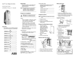
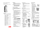
Note! This guide does not provide detailed installation, safety or operation instructions. See the ACS550 User’s Manual for complete information.
ACS550 - U1 - 08A8 - 4 + ...
DriveIT Low Voltage AC Drives
Install the Wiring
Quick Start Guide
Note!
ACS550-U1 Drives (1 to 200 Hp)
UL Type 1 / NEMA 1 / IP21
Wiring power
AC, Standard Drive - 550 series
Prepare for Installation
Warning! The ACS550 should ONLY be installed by a qualified electrician.
Unpack the Drive
Note! Use the following chart to interpret the type code found on the
drive label.
Lift ACS550 by its chassis and not by its cover.
1. Unpack the drive.
2. Check for any damage.
3. Check the contents against the order / shipping label.
Check
- Motor compatibility - Motor type, nominal current,
frequency, and voltage range must match drive specifications.
- Suitable environment - Drive requires heated, indoor
controlled environment that is suitable for the selected
enclosure.
- Wiring - Follow local codes for wiring, circuit protection, and
EMC requirements.
Refer to User’s Manual and confirm that all preparations are
complete.
Construction (region specific)
01 = Setup / parts for IEC install./compliance
U1 = Setup / parts for US install./compliance
Output current rating
See Ratings in User’s Manual for details
Voltage rating
2 = 208 ... 240 VAC
4 = 380 ... 480 VAC
6 = 500 ... 600 VAC
Enclosure protection class/Options
No specification = IP 21 / UL Type 1 / NEMA 1
B055 = IP 54 / UL Type 12 / NEMA 12
Prepare the Mounting Location
The drive requires a smooth, vertical, solid
surface, free from heat and moisture, with
free space for air flow - 200 mm (8 in) above
and below, and 25 mm (1 in) around the
sides of the drive.
1. Mark the mounting points.
Overview
The installation of the ACS550 adjustable speed AC drive follows the outline below.
2. Drill the mounting holes.
1. Open the appropriate knockouts in
the gland box.
2. Install the cable clamps for the
power/motor cables.
3. On the input power cable, strip the
sheathing back far enough to route individual wires.
4. On the motor cable, strip the
sheathing back far enough to expose
the copper wire screen so that the
screen can be twisted into a pig-tail.
Keep the pig-tail short to minimize
noise radiation. - 360° grounding
under the clamp is recommended for
the motor cable to minimize noise
radiation. In this case, remove the
sheathing at the cable clamp.
5. Route both cables through the clamps.
6. Connect the pig-tail created from the motor cable screen to
the GND terminal.
7. Strip and connect the power/motor wires, and the power
ground wire to the drive terminals. See
diagrams below, or Power connections
in User’s Manual.
8. Install conduit/gland box and tighten
the cable clamps.
Remove the Front Cover
Tools Required
Screwdrivers, wire stripper, tape measure, mounting screws
or bolts, and drill.
Collect Motor Data
Collect the following motor data from the motor nameplate for
later use in the ACS550 startup:
1. Remove the control panel, if attached.
2. Loosen the captive screw at the top.
3. Pull near the top to remove the cover.
Mount the Drive
Note!
Lift the ACS550 by its metal chassis.
1. Position the ACS550 onto the mounting screws or bolts and
securely tighten in all four corners.
2. Non-English speaking locations: Attach a warning sticker in
the appropriate language over the existing warning on the top
of the module.
Drive Identification
ACS550-U1-08A8-4
U1 3~380...480V I2N / I2hd 8.8/6.9 A
PN/Phd 5/3 Hp
Use separate conduit runs for input power, motor and control wiring.
Application
S/N
*2030700001*
3AUA0000001558 REVF
Effective: 10/01/2007
Supersedes: 10/30/2006
This guide provides a quick reference for installing
ACS550-U1 drives having a standard UL Type 1 (NEMA 1)
enclosure.
Warning! For IT systems and corner grounded TN systems, disconnect the internal EMC filter by removing screws: EM1 and EM3 (frame sizes
R1-R4), or F1 and F2 (frame sizes R5-R6).
Wiring the controls
Check installation
Apply power
1. Strip control cable sheathing
and twist the copper screen into a
pig-tail.
2. Route control cable(s) through
clamp(s) and tighten clamp(s).
3. Connect the ground screen pig-tail
for digital and analog I/O cables at
X1-1. (Ground only at the drive end.)
4. Connect the ground screen pig-tail
for RS485 cables at X1-28 or X1-32.
(Ground only at the drive end).
5. Strip and connect the individual
control wires to the drive terminals.
See Control connections below
or, for more information, see User’s
Manual.
Before applying power, perform the following checks.
Always reinstall the front cover before turning
power on.
1. Apply input power.
When power is applied to the ACS550, the green LED comes
on.
Note!
Before increasing motor speed, check that the
motor is running in the desired direction.
Start-up
In start-up, enter motor data (collected earlier)
Warning! The maximum voltage for digital inputs is 30 V.
and, if needed, edit parameters that define how
the drive operates and communicates.
6. Install the conduit/gland box cover (1 screw).
Warning! The ACS550 will start up automatically at power up, if the external run command is on.
Assistant Control Panel
ABB Standard Macro
The Start-up Assistant steps through typical start-up selections, and runs automatically upon the initial power up. At
other times, use the steps below to
run the Start-up Assistant.
1. Use the MENU key to access the
Main menu.
2. Select ASSISTANTS.
3. Select Start-up Assistant.
4. Follow the screen instructions to
configure the system.
Reinstall the cover
1. Align the cover and
slide it on.
2. Tighten the captive
screw.
3. Install the control
panel.
Note!
For common parameters and menu items,
use the Help key
to display descriptions.
If you encounter alarms or faults, use the Help key
or refer to chapter Diagnostics in User’s Manual.
Basic Control Panel
The Basic Control Panel does not include the Start-up Assistant. Refer to section “How to start up the drive” in the User’s
Manual and manually enter any parameter changes desired.
9. Install the cable clamp(s)
for the control cable(s).
(Power/motor cables and
clamps not shown in the
figure.)