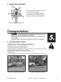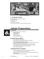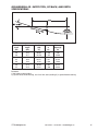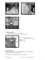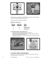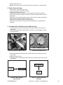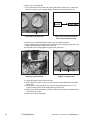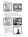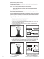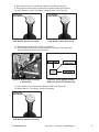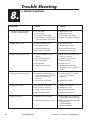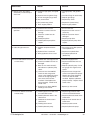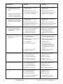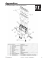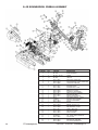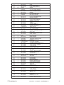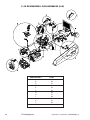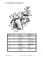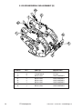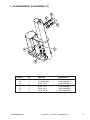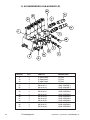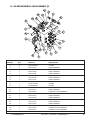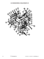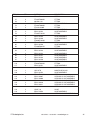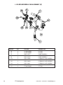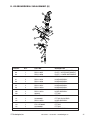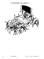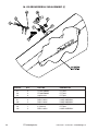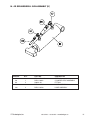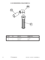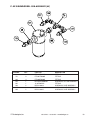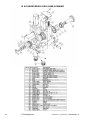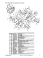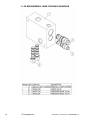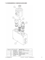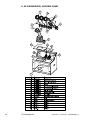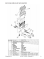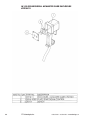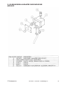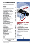
1
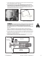
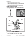
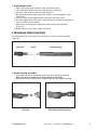
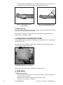
GRUNDODRILL
4X
STEERABLE BORING SYSTEM
User's Guide &
Safety Manual
Includes Maintenance Guide & Parts Listings
REVISION 1.0 • 8.31.02
Copyright© 2002, TT Technologies, Inc.
Table of Contents
2
1.
General Information
2.
Safety
3.
Technical Specifications
4.
Overview
5.
Transportation
6.
Jobsite Preparation
A. General Description. . . . . . . . . . . . . . . . . . . . . . . . . . . . . . . . . . . . . . . . . . . . . . . . . . . . .4
B. Forward . . . . . . . . . . . . . . . . . . . . . . . . . . . . . . . . . . . . . . . . . . . . . . . . . . . . . . . . . . . . . .4
C. General Use of the Operating Manual . . . . . . . . . . . . . . . . . . . . . . . . . . . . . . . . . . . . . . .4
A. General Safety Instructions . . . . . . . . . . . . . . . . . . . . . . . . . . . . . . . . . . . . . . . . . . . . . . .4
B. Owner and Operator Responsibilities . . . . . . . . . . . . . . . . . . . . . . . . . . . . . . . . . . . . . . .6
C. Training Requirements . . . . . . . . . . . . . . . . . . . . . . . . . . . . . . . . . . . . . . . . . . . . . . . . . .6
D. Staff Requirements . . . . . . . . . . . . . . . . . . . . . . . . . . . . . . . . . . . . . . . . . . . . . . . . . . . . .6
E. Accident Procedure . . . . . . . . . . . . . . . . . . . . . . . . . . . . . . . . . . . . . . . . . . . . . . . . . . . . .6
F. Protective Measures . . . . . . . . . . . . . . . . . . . . . . . . . . . . . . . . . . . . . . . . . . . . . . . . . . . .7
A. GRUNDODRILL 4X, Size Retracted and Extended . . . . . . . . . . . . . . . . . . . . . . . . . . . .8
B. Technical Data . . . . . . . . . . . . . . . . . . . . . . . . . . . . . . . . . . . . . . . . . . . . . . . . . . . . . . . . .8
A. Main Chassis . . . . . . . . . . . . . . . . . . . . . . . . . . . . . . . . . . . . . . . . . . . . . . . . . . . . . . . . . .9
B. Control Panel Overview . . . . . . . . . . . . . . . . . . . . . . . . . . . . . . . . . . . . . . . . . . . . . . . . . .9
C. Upper Control Panel . . . . . . . . . . . . . . . . . . . . . . . . . . . . . . . . . . . . . . . . . . . . . . . . . . .10
D. Remote Drive Control . . . . . . . . . . . . . . . . . . . . . . . . . . . . . . . . . . . . . . . . . . . . . . . . . .11
A. Loading Onto a Trailer . . . . . . . . . . . . . . . . . . . . . . . . . . . . . . . . . . . . . . . . . . . . . . . . . .11
B. Unloading From a Trailer . . . . . . . . . . . . . . . . . . . . . . . . . . . . . . . . . . . . . . . . . . . . . . . .12
A. General . . . . . . . . . . . . . . . . . . . . . . . . . . . . . . . . . . . . . . . . . . . . . . . . . . . . . . . . . . . . .12
B. Inspection of Jobsite . . . . . . . . . . . . . . . . . . . . . . . . . . . . . . . . . . . . . . . . . . . . . . . . . . .12
C. Preparation of the Jobsite . . . . . . . . . . . . . . . . . . . . . . . . . . . . . . . . . . . . . . . . . . . . . . .12
D. Setting Up the Jobsite . . . . . . . . . . . . . . . . . . . . . . . . . . . . . . . . . . . . . . . . . . . . . . . . . .13
E. Bore Planning . . . . . . . . . . . . . . . . . . . . . . . . . . . . . . . . . . . . . . . . . . . . . . . . . . . . . . . .14
TT Technologies,Inc.
1-800-533-2078 • 1-630-851-8200 • www.tttechnologies.com
7.
Operation
8.
Trouble Shooting
9.
Warranty Information
A. Safety Instructions as to Operator . . . . . . . . . . . . . . . . . . . . . . . . . . . . . . . . . . . . . . . . .16
B. Driving to Operation Site . . . . . . . . . . . . . . . . . . . . . . . . . . . . . . . . . . . . . . . . . . . . . . . .16
C. Set up of Safety Alert Package . . . . . . . . . . . . . . . . . . . . . . . . . . . . . . . . . . . . . . . . . . .18
D. Auger Staking Drill in Place . . . . . . . . . . . . . . . . . . . . . . . . . . . . . . . . . . . . . . . . . . . . . .20
E. Preparing Sonde Housing . . . . . . . . . . . . . . . . . . . . . . . . . . . . . . . . . . . . . . . . . . . . . . .21
F. Connecting the Bentonite System . . . . . . . . . . . . . . . . . . . . . . . . . . . . . . . . . . . . . . . . .22
G. Bore Mode . . . . . . . . . . . . . . . . . . . . . . . . . . . . . . . . . . . . . . . . . . . . . . . . . . . . . . . . . . .22
A. Trouble Shooting . . . . . . . . . . . . . . . . . . . . . . . . . . . . . . . . . . . . . . . . . . . . . . . . . . . . . .28
A. Warranty . . . . . . . . . . . . . . . . . . . . . . . . . . . . . . . . . . . . . . . . . . . . . . . . . . . . . . . . . . . .31
10. Maintenance
A. Service Intervals . . . . . . . . . . . . . . . . . . . . . . . . . . . . . . . . . . . . . . . . . . . . . . . . . . . . . .32
B. Lubrication Products and Oil Table . . . . . . . . . . . . . . . . . . . . . . . . . . . . . . . . . . . . . . . .33
C. Jaw Removal & Replacement . . . . . . . . . . . . . . . . . . . . . . . . . . . . . . . . . . . . . . . . . . . .34
11. Appendices
A. Vise Control Block . . . . . . . . . . . . . . . . . . . . . . . . . . . . . . . . . . . . . . . . . . . . . . . . . . . .35
B. Overall Assembly . . . . . . . . . . . . . . . . . . . . . . . . . . . . . . . . . . . . . . . . . . . . . . . . . . . . .36
C. Sub-Assemblies (A-M) . . . . . . . . . . . . . . . . . . . . . . . . . . . . . . . . . . . . . . . . . . . . . . . . .38
D. Sub-Assembly A . . . . . . . . . . . . . . . . . . . . . . . . . . . . . . . . . . . . . . . . . . . . . . . . . . . . . .39
E. Sub-Assembly B . . . . . . . . . . . . . . . . . . . . . . . . . . . . . . . . . . . . . . . . . . . . . . . . . . . . . .40
F. Sub-Assembly C . . . . . . . . . . . . . . . . . . . . . . . . . . . . . . . . . . . . . . . . . . . . . . . . . . . . . .41
G. Sub-Assembly D . . . . . . . . . . . . . . . . . . . . . . . . . . . . . . . . . . . . . . . . . . . . . . . . . . . . . .42
H. Sub-Assembly E . . . . . . . . . . . . . . . . . . . . . . . . . . . . . . . . . . . . . . . . . . . . . . . . . . . . . .43
I. Sub-Assembly F . . . . . . . . . . . . . . . . . . . . . . . . . . . . . . . . . . . . . . . . . . . . . . . . . . . . . .44
J. Sub-Assembly G . . . . . . . . . . . . . . . . . . . . . . . . . . . . . . . . . . . . . . . . . . . . . . . . . . . . . .46
K. Sub-Assembly H . . . . . . . . . . . . . . . . . . . . . . . . . . . . . . . . . . . . . . . . . . . . . . . . . . . . . .47
L. Sub-Assembly I . . . . . . . . . . . . . . . . . . . . . . . . . . . . . . . . . . . . . . . . . . . . . . . . . . . . . . .48
M. Sub-Assembly J . . . . . . . . . . . . . . . . . . . . . . . . . . . . . . . . . . . . . . . . . . . . . . . . . . . . . .50
N. Sub-Assembly K . . . . . . . . . . . . . . . . . . . . . . . . . . . . . . . . . . . . . . . . . . . . . . . . . . . . . .51
O. Sub-Assembly L . . . . . . . . . . . . . . . . . . . . . . . . . . . . . . . . . . . . . . . . . . . . . . . . . . . . . .52
P. Sub-Assembly M . . . . . . . . . . . . . . . . . . . . . . . . . . . . . . . . . . . . . . . . . . . . . . . . . . . . . .53
Q. Drill Head Assembly . . . . . . . . . . . . . . . . . . . . . . . . . . . . . . . . . . . . . . . . . . . . . . . . . . .54
R. Wrench Assembly . . . . . . . . . . . . . . . . . . . . . . . . . . . . . . . . . . . . . . . . . . . . . . . . . . . . .55
S. Loop Flushing Manifold . . . . . . . . . . . . . . . . . . . . . . . . . . . . . . . . . . . . . . . . . . . . . . . . .56
T. Cushion Valve Block . . . . . . . . . . . . . . . . . . . . . . . . . . . . . . . . . . . . . . . . . . . . . . . . . . .57
U. Control Panel . . . . . . . . . . . . . . . . . . . . . . . . . . . . . . . . . . . . . . . . . . . . . . . . . . . . . . . .58
V. Main Valve Manifold . . . . . . . . . . . . . . . . . . . . . . . . . . . . . . . . . . . . . . . . . . . . . . . . . . .59
W. McMaster Carr Enclosure #9215K11 . . . . . . . . . . . . . . . . . . . . . . . . . . . . . . . . . . . . . .60
X. McMaster Carr Enclosure #9215K12 . . . . . . . . . . . . . . . . . . . . . . . . . . . . . . . . . . . . . .61
TT Technologies,Inc.
1-800-533-2078 • 1-630-851-8200 • www.tttechnologies.com
3
General Information
A. GENERAL DESCRIPTION
1.
This operating manual deals with general safety instructions for operation of the machine
as well as technical data and explanations as to the set-up and functioning of the
machine.
B. FORWARD
This operating manual is considered to be an integral part of the GRUNDODRILL 4X
system. It is an essential part of the user documentation. Adhering to the information,
instructions and data in this manual is critical to successful equipment operation.
Technical data or information is subject to alteration without notice.
If you have questions or ideas concerning these products or this manual, please contact:
TT Technologies, Inc. 1-800-533-2078 or 1-630-851-8200.
C. GENERAL USE OF THE OPERATING MANUAL
This operating manual details the safe, correct and proper usage of the Grundodrill 4x
Drill, as well as the type of applications in which it is designated for. Adhering to the
instructions, will reduce the risk of danger, repair costs and down time, while increasing
the reliability of the machine.
Local regulations regarding prevention of accidents and safeguarding the environment
should be adhered to in addition to those outlined in the operating manual.
This manual should be made available at every jobsite, at all times.
The operating manual should be read and the instructions applied by each person who
works with the machine:
• During operation (including set-up, troubleshooting during operation, jobsite
cleanup, maintenance, disposal of lubricants)
• During maintenance, inspection, repair
• Transportation
Besides the instructions of the operating manual and the regulations of safety prevention
from the respective country or site of use, standard industry regulations for safety and
operation practices should also be adhered to.
Safety
A. GENERAL SAFETY INSTRUCTIONS
2.
All safety devices and warning labels should not to be changed or removed from the
machine.
Adhere to all instructions concerning safety and possible danger!
Keep all labels regarding safety and possible dangers on the machine in good, readable
condition.
In case of safety relevant modifications to the machine or its operating mode, stop the
machine immediately and notify the person in charge.
SAVE THESE INSTRUCTIONS
4
TT Technologies,Inc.
1-800-533-2078 • 1-630-851-8200 • www.tttechnologies.com
Only qualified and trained personnel should carry out operation of the machine.
Before starting the machine all safety requirements must be fulfilled.
Designated personnel should thoroughly study the operating manual, including all safety
instructions and warnings, prior to the use of the machine.
New operators and operators in training should work under constant supervision of a
qualified operator only!
The GRUNDODRILL is manufactured to the current technical safety-relevant regulations.
Nevertheless, the use of the machine may represent a danger to the health and life of
users or third parties. Always ensure that you pay particular attention to warnings,
safety labels and instructions.
Read Operators Manual
Before starting the machine, fulfill all safety related requirements. All personnel
should thoroughly read this operating manual.
Follow all safety instructions concerning safety and possible danger. Do not
modify or remove the safety devices or warning labels of this machine. Keep
all labels regarding safety and possible danger on the machine in good,
readable condition. Special care is required before and during the safety check.
Every crew member should fully understand the safety measures required for
the operation and should be capable of following these regulations individually.
Call Before You Dig
Check the existence and exact position of buried pipe and cables by
contacting the respective utilities or owners of networks. The exact and
definite existence and position of buried cables and pipes should be defined by
trial pits or using cable and pipe detection equipment or other means.
Cable Strike
Should you accidentally hit an electrical cable, immediately leave the site,
ensure no one enters and contact the electrical company to turn off the supply.
In case of a cable strike, the danger resulting from that damaged electric cable
can only be evaluated following detailed information by the respective
electrical company. Never rely on your own knowledge as to types of cables,
safety measures and protective measures that may not be correct for the type
of cable encountered. Always consider cables to be “live” and a potential
danger to life. Do not re-enter the site until authorized by the electrical company.
No Loose Clothes
Do not wear loose clothes or long hair. Danger of body injury by loose clothes
or hair being caught in the moving parts of the machine.
Safety Equipment
The operating crew should always wear the appropriate safety equipment, i.e.,
safety shoes/boots, hard hat, safety glasses, gloves, ear protection etc.
Operation by Qualified Personnel Only
Operation of the GRUNDODRILL should be carried out by suitably trained,
qualified, and certified personnel only. New operators or operators in training
should be working under the constant supervision of a qualified person.
Personnel operating the GRUNDODRILL should have sufficiently studied the
operating manual.
SAVE THESE INSTRUCTIONS
TT Technologies,Inc.
1-800-533-2078 • 1-630-851-8200 • www.tttechnologies.com
5
B. OWNER AND OPERATOR RESPONSIBILITIES
The machine owner is obligated to restrict the operation of the machine to operators that:
• Have been made aware of basic regulations for work safety and accident
prevention, and have been instructed in the correct operation of the machine.
• Have read and fully understood the operating manual, particularly the chapter
on safety.
• Have been trained and instructed, and whose responsibilities as to operating,
setting up, maintaining and repairing the machine have been clearly defined!
The operating personnel should carry out regular checks to verify safety conscious use
of the machine.
The operating personnel should:
• Be qualified and trained in the respective field of application and should be
familiar with the handling of the machine.
• Be informed at regular intervals about difficulties, dangers, and special
procedures for operation of the machine.
C. TRAINING REQUIREMENTS
To attain maximum knowledge about the use of this system, the operators should be
trained by TT Technologies’ personnel.
Only trained and qualified personnel are permitted to work on the machine.
Responsibilities of the staff as to the operation, set-up, maintenance and repair of the
system are to be clearly defined.
New operators, or operators in training, should work under the constant supervision of
qualified and experienced personnel only!
D. STAFF REQUIREMENTS
At least 2 workers are required for set-up, disassembly and operation of the
GRUNDODRILL 4X boring system.
Before starting to bore all personnel charged with the use of the machine, are obligated to:
• Follow the basic work safety and accident prevention regulations.
• Thoroughly read the operating manual, particularly the safety instructions, and
confirm that they have been fully understood.
• Use personal or work related protection clothing, or other means, to guarantee
safety during the operation of the machine.
E. ACCIDENT PROCEDURE
• Cease immediately operations.
• Take the necessary protective steps according to the type of cable or pipe.
• Notify the owner of the cable or pipe.
• Estimate the type and extent of the damage.
• Warn pedestrians and house occupants, and keep them away from the danger.
6
TT Technologies,Inc.
1-800-533-2078 • 1-630-851-8200 • www.tttechnologies.com
F. PROTECTIVE MEASURES
In case of a telephone cable:
• Respect the cable protection instructions of the local telephone company.
• Notify the local telephone company.
CAUTION: Do not look closely at glass fiber cable! Risk of eye injury.
In case of electrical cable:
• Machine operator should not leave the machine
• Stay a safe distance from the machine
• Observe cable protection instructions
• Contact respective power company
DANGER: Electrical strike could result in severe personal injury or death.
In case of gas pipes:
• Do not operate with open flame
• Extinguish all flames, do not light new flames
• Shut down all engines
• Do not operate electric buttons or withdraw cable plugs
• Inform the respective gas company
WARNING: When smelling gas: risk of explosion!
In case of water pipes:
• Obtain information on the next available valve closing
• Call the local utility service department
In case of sewage pipes:
• Never enter into manholes or sewage mains alone
• Never enter into manholes or sewage mains without the proper safety gear
• Inform the respective owner of the pipe
TT Technologies,Inc.
1-800-533-2078 • 1-630-851-8200 • www.tttechnologies.com
7
Technical Specifications
A. GRUNDODRILL 4X, SIZE RETRACTED & EXTENDED
3.
Figure 1. GRUNDODRILL 4X
B. TECHNICAL DATA
Grundodrill 4X Specifications
Engine:
Length x Width x Height:
Weight including drill stems:
Pull back:
Thrust:
Max Torque:
Spindle Speed:
Diameter Pilot Bore:
Diameter Drill Rod:
Length Drill Rod:
Diameter Back Ream:
Pipe OD:
Bore Length:
37.5 HP
130 in x 35.5 in x 70.5 in
4100 lbs
9,500
9,500
1,100 ft-lbs
230 rpm
2.5 in
1.75 in
60 in
8 in
6 in (dependent on conditions)
dependent on conditions
Specifications subject to change at any time.
Grundomudd 225 Bentonite System
Engine:
Length x Width x Height:
Weight:
Capacity:
Max Operating Pressure:
Max Operating Flow:
9.5 HP (gas) or 7.5 HP (diesel)
72 in x 46 in x 46 in
650 lbs
225 gal (larger sizes available)
800 psi
10 gpm
Figure 2. Technical Data
8
TT Technologies,Inc.
1-800-533-2078 • 1-630-851-8200 • www.tttechnologies.com
Overview
A. MAIN CHASSIS
4.
B
F
D
M
G K
L
J
E
I
C
D
O
A
N
H
Figure 3. GRUNDODRILL 4X
A)
B)
C)
D)
E)
F)
G)
H)
Rear Stabilizer
Remote Track Drive
Diesel Engine
Drill Stem Carrier
Spindle Drive
Remote Stake Down
Stake Down Motor
Stem Whippier
I) Smart Vise
J) Thrust & Pullback Motor
K) Zap Alert
L) Control Panel
M) Operators Seat
N) Steel Track, w/Grounded Rubber
O) Track Drive Motor
B. CONTROL PANEL OVERVIEW
Figure 4. Upper Panel
TT Technologies,Inc.
1-800-533-2078 • 1-630-851-8200 • www.tttechnologies.com
9
Figure 5. Control Panel
Figure 6. Lower Panel
Figure 7. Joystick Control
Figure 8. Joystick
C. UPPER CONTROL PANEL
A
E
B
F
G
C
H
I
D
J
K
L
M
Figure 9. Upper Control Panel
A)
B)
C)
D)
E)
F)
G)
10
Rotation Pressure (psi or bar)
Thrust Pressure (psi or bar)
Drill Fluid Pressure (psi or bar)
Ignition Switch (Preheat/Off/On/Start)
Strobe Light (On/Off)
Work Light (On/Off)
Head Cushion (On/Off)
TT Technologies,Inc.
H) Front Vice (Open/Closed)
I) Rear Vice (Open/Closed)
J) Wrench (Break Loose/Close)
K) Glow Plug Lamp (On-Preheating Plugs)
L) Hyd Filter Lamp (On-Electrical System)
M) Charge Lamp (On-Electrical System)
1-800-533-2078 • 1-630-851-8200 • www.tttechnologies.com
D. REMOTE DRIVE CONTROL
A
B
C
E
A)
B)
C)
D)
E)
Emergency Stop (Push-Stop/Pull-Reset)
Speed Control (Low/High)
Left Track (Forward/Neutral/Reverse)
Master Button (Push-Engages Drives)
Right Track (Forward/Neutral/Reverse)
D
Figure 10. Remote Drive Control
Transportation
• Never allow riders on the boring unit while moving or loading.
• Always load and unload trailers on level ground.
• Make sure boring rig is loaded correctly onto trailer, according to trailer
size and type.
• Check that trailer is attached to vehicle before loading and unloading.
A. LOADING ONTO TRAILER
5.
1. Make sure trailer is rated for the boring rigs size and weight.
2. Make sure trailer is correctly attached to towing vehicle.
3. Move boring rig to rear of trailer (Figure 11).
4. Align ramps with boring rig tracks (Figure 11).
5. With idle speed on low, and boom and stabilizer raised, slowly load boring rig onto trailer.
6. Position boring rig correctly on trailer (Figure 12).
7. Lower boom and stabilizer until they lay firmly on the trailer.
8. Shut engine off.
9. Attach boring rig to trailer with tie downs, & use the proper tie down locations (Figure 13).
Figure 11. Prepare Rig for Trailer
TT Technologies,Inc.
Figure 12. Position on Trailer
1-800-533-2078 • 1-630-851-8200 • www.tttechnologies.com
11
A
B
Figure 13. Tie Down Points
B. UNLOADING TRAILER
1. Make sure you are unloading on level ground.
2. Remove tie downs.
3. Lower trailer ramps.
4. Start engine.
5. Raise boom and stabilizer.
6. At a slow idle, slowly and cautiously back boring unit off trailer.
Jobsite Preparation
6.
A. GENERAL
Many elements go into having a successful bore.
• Qualified Operators
• Jobsite Inspection
• Jobsite Planning
• Preoperational setup
• Proper setup and operation
B. INSPECTION OF JOBSITE
• Can the jobsite be easily reached?
• At which position is the starting point of the bore best suited?
• Where and how will the working pits be dug?
• Can the entire bore be done without any obstacles? (foundations, pipes, steel)
• Where will the bentonite system be located?
• Will the bentonite system hoses and electrical reach the boring unit?
• Will the bentonite system be refillable where and how it is positioned?
• Can the bore head be located in the length of the bore?
• What are the soil conditions?
C. PREPARATION OF THE JOBSITE
• Is there a complete location drawing of all buried cables and pipes?
• Have you called the local "One Call" for utilities?
• Have all buried cables and pipes been located, and exposed if needed, by the
proper services?
• Have all required permits been obtained?
12
TT Technologies,Inc.
1-800-533-2078 • 1-630-851-8200 • www.tttechnologies.com
• What will the bore path be?
• What will be the entry position?
• Has the water source for the Bentonite system been identified?
• Is the pipe on site?
• What is the outside diameter of the pipe?
• Do you have the correct size backreamer to pull-in the O.D. of the product pipe?
• What are the individual lengths of product pipe?
• Does the contractor have the proper equipment to connect pipe? (fusion machine)
• How big should the pits be?
• Will there be any support personnel or lifting equipment?
• How and who will empty the pits of the drilling fluid to recycle the mud?
• Who assumes responsibility for accidents or various contractual shortcomings?
• Who assumes responsibility for environmental hazards?
D. SETTING UP THE JOBSITE
• Has the jobsite been prepared according to specifications?
• Have all maintenance procedures been properly carried out?
• Have all the safety precautions been taken?
• Has the Grundodrill 4x bore rig been properly positioned according to specifications?
• Are all the necessary boring tools and accessories available on site?
• Has the jobsite been marked off according to safety specifications?
• Secure the bore rig and operating space.
TT Technologies,Inc.
1-800-533-2078 • 1-630-851-8200 • www.tttechnologies.com
13
E. BORE PLANNING
Proper bore planning is critical to project success. Several considerations must be made
in order to ensure a successful bore. These items include:
• Bend Radius
• Launch & Exits
• Minimum Set back
• Minimum Depth
• Pitch
1. Bend Radius
Creating the bore path depends on the bending of the drill stems. Creating bore paths
that exceed the recommended bend radius of the drill stems will cause damage. Taking
into consideration the minimum drill stem bend radius is essential to planning the bore
path. Minimum bend radius for the drill stems used with the Grundodrill 4X is 96'.
2. Launch Area & Exit Pit
Launch area and exit pit should be selected to provide optimum drilling conditions. The
launch area needs to be located where there is enough space to accommodate all
drilling equipment and machinery and remain a safe distance from vehicle and
pedestrian traffic. The launch area should also accommodate the drilling mud system.
3. Minimum Set-back (SB)
Because steering is dependent on the bending of the drill pipe, the drill needs to be
positioned far enough back to accommodate the bending of the drill stem. The set-back
distance is the length from entry to horizontal. To determine the necessary minimum set
back refer to the chart and drawing found on the next page.
4. Minimum Depth (D)
Minimum depth is another consideration when positioning the Grundodrill 4X machine.
Refer to the chart and drawing found on the next page to determine the minimum depth
requirement for the specific bore path.
5. Pitch or Angle (EP or EA)
The entry pitch or entry angle at which the drill stem enters the ground directly affects the
depth and length of the bore path. The entry pitch or entry angle is the Grundodrill 4X
machine slope compared to level ground. Refer to the chart and drawing found on the
next page to determine the entry pitch or entry angle requirement for the job.
14
TT Technologies,Inc.
1-800-533-2078 • 1-630-851-8200 • www.tttechnologies.com
GRUNDODRILL 4X - ENTRY PITCH, SET-BACK, AND DEPTH
SPECIFICATIONS
Entry
Pitch
(EP)
26
28
30
32
34
36
38
40
42
Entry
Angle
(EA)
14.6
15.6
16.7
17.7
18.8
19.8
20.8
21.8
22.8
Set-Back
(SB)
(ft)
29.057
30.632
32.376
33.95
35.671
37.22
38.764
40.294
41.811
d
(ft)
1.26
1.345
1.437
1.52
1.611
1.694
1.776
1.857
1.938
Minimum
Depth (D)
(ft)
4.36
4.88
5.486
6.065
6.733
7.369
8.032
8.722
9.439
Based on:
1) 96' minimum bend radius.
2) (d) Drill head, sonde housing, and 1/2 of first stem (totalling 5') in ground before steering.
TT Technologies,Inc.
1-800-533-2078 • 1-630-851-8200 • www.tttechnologies.com
15
Operation
7.
A. SAFETY INSTRUCTIONS AS TO OPERATOR
• Operating personnel should thoroughly study the operating manual, specifically
the chapter on safety instructions, prior to the using the machine. During the
operation of the boring rig it is too late to study the operating manual! This is
particularly true for operators that use the machine on an irregular basis for set
up, maintenance or during operation.
• Daily check all hoses, pipe lines and securing bolts for correct position and
function before starting the bore! Visual Check!
• Use only oils and lubricants recommended by the manufacturer!
• Only qualified and trained personnel should use the machine!
• Each member of the crew should fully understand the safety measures required
for the operation and each one should be capable of the following the
instructions individually.
• New operators or operators in training should be working under the constant
supervision of a qualified and experienced persons only!
• Adhere to the legal minimum age for operators.
• Use only the machine in sound technical condition after having studied the
operating manual, particularly the safety related aspects.
• Any safety disturbances should immediately be eliminated.
• Rotating and moving parts can present a dangerous situation: pulling or
wrapping around.
• Open safety covers, doors, and other equipment only after shut down of the
machine.
• The working area should be secured so the machine system contact with the
public is prevented.
• Should a dangerous situation arise, toward people or the machine, immediately
push the emergency ON-OFF button.
• Never operate the machine without properly installing the electric strike
protection system.
• In case of an electrical strike the operator should NEVER leave the bore rig
safety mats until there is a 100% confirmation that electrical source has been
shut down.
• In case of cable strike, the respective electrical company can only evaluate the
danger resulting from that damaged electric cable following detailed information.
• Never rely solely on your own knowledge as to the types of cable encountered.
• The entire bore crew should wear functional protective attire, including ear
protection.
B. DRIVING TO OPERATION SITE
1. Safety Instructions
• Do not drive bore rig on steep slopes.
• Lift bore rig boom and rear stabilizer before moving rig.
• Always walk with machine while driving, DO NOT RIDE ON BORE RIG!
• Do not drive over any hydraulic hoses, bentonite hoses, or control cables.
• When driving bore rig off or on trailer refer to safety instructions in chapter 5.
2. Control Steps Prior to Starting
• Check the coolant level (Figure 14).
• Check the oil level (Figure 15).
• Check the diesel level (Figure 16).
16
TT Technologies,Inc.
1-800-533-2078 • 1-630-851-8200 • www.tttechnologies.com
Figure 15. Check Oil Level
Figure 14. Check Coolant Level
Figure 16. Check Diesel Level
3. Starting the Motor
1. Turn key to right to position 4 to start (Figure 17).
2. Release key as soon as engine fires (key will be in position 3).
2
Position 1
3
1
4
Position 2
Position 3
Position 4
Preheat Glow Plugs
(Only necessary for cold starting)
Off
On
Start
Figure 17. Starting the Motor
4. Driving Bore Rig
Drive bore rig to operations site using the remote drive control. While driving
bore rig adhere to all prior safety instructions.
For remote drive control switch positions refer to chapter 4 D.
TT Technologies,Inc.
1-800-533-2078 • 1-630-851-8200 • www.tttechnologies.com
17
Figure 19. Remote Drive Control
Figure 18. Remote Drive Control
To drive boring, move toggles to desired direction and then press Master Button
and hold to put boring rig into motion (Figure 18).
To stop boring rig just release Master Button.
Toggle Steering Controls
Left Track
Right Track
F
N
F
F
N
R
F
N
N
R
F
F
Action
Forward
Neutral
Gradual Right Turn
Sharp Right Turn
Gradual Left Turn
Sharp Left Turn
5. Setting Up the Bore Rig for Operation
1. Drive the bore rig to the operating entry position (Figure 20).
2. Raise rear stabilizer to the height desired for entry angle. Using rear stabilizer
toggle located on lower panel, (Figure 21).
3. Lower boom until boom plate is lying firmly on the ground. Using Boom toggle on
lower panel, (Figure 21).
Figure 21. Lower Panel
Figure 20. Operating Entry Position
C. SET UP OF SAFETY ALERT PACKAGE
After the boring rig is in place the safety alert package for the boring rig must be set in
place before boring or staking down of rig.
18
TT Technologies,Inc.
1-800-533-2078 • 1-630-851-8200 • www.tttechnologies.com
1. Take the grounding rod, connected to the zap-alert system and unwrap cord from
the rig and extend the cord out (Figure 22).
2. Push the grounding rod into the ground-approximately five to six feet away
from the boring rig, and perpendicular to the boring path (Figure 23). (If an
electrical strike has been made, the siren will continue to sound as long as current
is passing into the machine and soil. If you attempt to reset the zap-alert, the
siren will not stop until the current has stopped.
Grounding
Rod
Zap
Alert
Figure 22. Zap Alert & Grounding Rod
Figure 23. Grounding Rod
Do not stop the siren by resetting the zap-alert until you have
confirmed that the electric power has been locked out. If the power has not
been properly shut off, an automatic resetting circuit breaker could
re-energize the power line, or contact between the boring rig and power line
may recur.
Danger: The operator is not to leave the machine until all safety and
electrical shut offs are confirmed and done according to safety standards.
3. Place the safety mat out parallel to the bore rig, and plug the cable into one of the
sockets on the bore rig (a second safety mat can be laid out on the other side of
the bore rig as an option) (Figure 24).
4. Connect the grounding stake to the other socket and insert the stake vertically,
next to the bore rig, away from the safety mat (Figure 24).
Grounding
Rod
Safety Mat
Zap-Alert
Optional
Safety Mat
Figure 24. Overhead of Safety Alert Package
TT Technologies,Inc.
1-800-533-2078 • 1-630-851-8200 • www.tttechnologies.com
19
Safety Warnings
• Electrical strike could result in severe personal injury or death.
• Never start a bore without prior setting up of the complete safety kit!
• When placing stakes in the ground, the operator must be wearing electrical safety
boots and gloves.
• It is important that the stake is placed in conductive soil.
• In extremely dry or asphalted soils prior watering of the ground is necessary.
D. AUGER STAKING DRILL IN PLACE
The bore rig comes with four auger stakes to secure rig to ground (Figure 25).
The staking system is operated using a remote, which is located on the auger
stake down (Figure 26 & Figure 27).
Figure 25. Auger Stake
Figure 26. Auger Remote
Locking
Pin
Operators
Seat
Control Panel
Auger
Motor
Zap Alert
Auger Stake
Line of Entry
Auger Stake
Alignment Holes
Figure 27. Stake Down System
The remote has two toggle switches (Figure 26).
1. Auger rotation (toggle up = auger in, toggle down = auger out)
2. Auger thrust up and down, rotates drive motor.
20
TT Technologies,Inc.
1-800-533-2078 • 1-630-851-8200 • www.tttechnologies.com
1. Setting Auger Stake
1. Bore rig must be running to operate auger stake down system.
2. Lock stake down guide into position using locking pin (Figure 27).
3. Place the auger stake into alignment hole (Figure 27).
4. Bring auger motor down onto auger stake until pins are fully engaged in auger
motor chuck.
5. Push the auger rotation toggle forward to lock stake into auger chuck.
6. Run both toggles forward, this will put downward thrust and clockwise rotations on
auger, screwing it into the ground.
7. Stop rotation and thrust when auger plate reaches top on alignment hole
(Figure 27).
8. Repeat steps 2-7 until all four augers are in place.
E. PREPARING SONDE HOUSING
The drilling tool consists of the drill head, sonde housing and the transmitting sonde
(Figure 28).
Drill Head
Sonde
Sonde Housing
Figure 28. Drill Head, Sonde, Sonde Housing
1. Sonde Housing Assembly
1. Slide sonde into drill head matching sonde slot to pin in drill head (Figure 29).
Note: This will lock sonde to 12 o’clock position on drill head.
2. Slide sonde and rear of drill head into sonde housing, with pin aligned (Figure 30).
Figure 29. Slide Sonde into
Drill Head
TT Technologies,Inc.
Figure 30. Slide Sonde & Rear of
Drill Head into Sonde Housing
1-800-533-2078 • 1-630-851-8200 • www.tttechnologies.com
21
3. Rotate boring head 90 degrees in sonde housing until pins lock in place (Figure 31).
4. Insert cap screws to lock drill head onto sonde housing (Figure 32).
Figure 31. Rotate 90° Until Pin
Locks in Place
Figure 32. Insert Cap Screws to Lock
Drill Head onto Sonde Housing
2. Calibrate Sonde
After preparing the sonde housing assembly, calibrate sonde in sonde housing according
to the type of locating equipment being used.
With calibration complete, test sonde housing assembly with locating equipment for
proper depth, roll, and pitch reading.
F. CONNECTING THE BENTONITE SYSTEM
The standard Bentonite system to be used with the 4X-boring rig is the TT Technologies
225 Bentonite system.
The connection of the Bentonite system consists of two hook-ups, the Bentonite hose
and electrical connection (Figure 33).
Figure 33. 4X GRUNDODRILL
Bentonite & Electrical Connections
For operation of bentonite system, see bentonite systems manual.
G. BORE MODE
1. Safety Instructions
• The entire crew should read and fully understand all general safety instructions and
operating safety instructions.
• Operators strict attention is required during the rotation mode!
• Danger of injury around all moving parts.
22
TT Technologies,Inc.
1-800-533-2078 • 1-630-851-8200 • www.tttechnologies.com
• No loose clothing or hair.
• Never have physical contact with stem while stem or spindle is in rotation mode.
2. Checks Prior to Boring
• Check the drill stem for fatigue or wear.
• Visual check of the o-ring on the drill stem.
• Check bore rig fluids for start-up.
• Has bentonite fluid been mixed and is the mixing system ready for operation?
• Check that all hoses and electrical cables have been connected correctly and are
operational.
• Make sure that all communications (radio or hand signal) have been agreed upon
between location operator and bore rig operator.
• Check that all safety precautions have been applied.
• Make sure that the strike alert system has been tested and is in good working
condition.
3. Assembly of First Drill Stem with Sonde Housing
1. Take first stem in the left hand and place the male end of the stem in the vice
(Figure 34).
2. With auto vice selected in the off position, close rear vice using toggle on upper
panel (Figure 35).
Figure 34. Place First Stem in Vice
Figure 35. Close Rear Vice
3. Move the spindle head forward until the head leads into the female side of stem
(Figure 36).
4. Release hand from stem.
5. Using the joystick rotate the bore head clockwise until head screws into first stem
(Figure 37).
Figure 36. Move Spindle
Head Forward
TT Technologies,Inc.
Figure 37. Rotate Bore Head
Clockwise
1-800-533-2078 • 1-630-851-8200 • www.tttechnologies.com
23
6. Open rear vice (Figure 38).
7. Thrust stem forward until male end of stem protrudes the Smart Vice. Make sure
both front and rear vices are open before thrusting stem forward (Figure 39).
Figure 38. Open Rear Vice
Figure 39. Thrust Stem Forward
until it Protrudes Smart Vice
8. Manually turn on Bentonite fluid to flush away any foreign materials.
9. Screw sonde housing assembly onto male end of stem protruding (Figure 40) and
tighten sonde housing assembly with a wrench.
10. Open both vices using toggles on upper panel (Figure 41).
Figure 40. Screw Sonde Housing
Assembly onto Male End
Figure 41. Open Both Vices Using
Toggles on Upper Panel
11. Rotate drill head to the 6 o’clock position.
12. With Bentonite system running, turn drill fluid on to check whether drill fluid exits
bore head.
13. Using joystick thrust spindle forward until drill head penetrates about 12 – 18
inches into the ground, while keeping drilling fluid running.
14. With joystick rotate (clockwise) and thrust drill head forward until spindle forward
thrust comes to a stop.
15. Switch drill fluid to off position.
24
TT Technologies,Inc.
1-800-533-2078 • 1-630-851-8200 • www.tttechnologies.com
4. Drilling Operation
1. Switch drill fluid toggle to auto (Figure 42).
2. Switch Head Cushion to ON position (Figure 43).
Figure 42. Switch Drill Fluid
Toggle to Auto
Figure 43. Switch Head Cushion
to ON Position
3. Switch auto vice selector in the Smart Vice to drill out (Figure 44).
4. Press the Smart Vice cycle button on joystick to close front vice.
5. Unscrew spindle head from stem by counter rotating the spindle by pulling back on
the joystick.
6. Once spindle is completely unscrewed from the stem, pull the joystick to the left
and thrust spindle drive into head cushion, this action then places spindle drive
into the beginning position.
7. Place next drill stem into position (Figure 45).
Figure 44. Switch Auto Vice Selector
in the Smart Vice to Drill Out
8. Rotate spindle head and thrust forward
until stem is tightened between head
and previous stem.
9. Hit Smart Vice cycle button (Figure 46)
(This will release front vice and turn
bentonite fluid on).
10. At this point you can thrust in for
steering or rotate for straight boring.
11. Run stem in until spindle head hits the
forward stop.
12. Repeat steps 4-11 until exit location is
reached.
Figure 45. Place Next Drill Stem
into Position
Smart Vice
Cycle Button
Figure 46. Hit Smart Vice
Cycle Button
TT Technologies,Inc.
1-800-533-2078 • 1-630-851-8200 • www.tttechnologies.com
25
5. Pre-reaming / Back-reaming
When the bore head reaches the target location and the sonde housing is exposed, a
change of tooling is required.
Note: Shut off boring rig before making any tooling changes.
Danger: Stay away from any turning, stem contact may and can cause
injury or death.
If the pilot bore is larger than the product pipe, remove the sonde housing and replace
with a swiveled piping eye for back pull.
When the pilot bore needs to be expanded to a larger diameter than that of the pilot bore,
a change of tooling is than required. The sonde housing is exchanged for a backreamer.
When all tooling is changed and all personnel are clear of the tooling attachment, start
engine of bore rig.
1. Bentonite system must be running and connected.
2. Drill Fluid switch needs to be in auto position.
3. Flip auto vice select to the pull back position.
4. Cycle Smart Vice™ button by pressing four times, until both vices are open, and
bentonite fluid is flowing (Figure 47).
5. Using the joystick rotate clockwise and thrust in drill stem until spindle hits the
head cushion (Figure 48).
Smart Vice
Cycle Button
Figure 47. Cycle Smart Vice Button
by Pressing Four Times
Figure 48. Using Joystick Rotate
Clockwise and Thrust in Drill Stem
6. Press the Smart Vice™ cycle button (Figure 49). (Causing front vice to lock, shut
bentonite off, rear wrench will lock and break stem joint and then release.)
7. Counter rotate and thrust back about a 1/2" to disengage stems (Figure 50).
Smart Vice
Cycle Button
Figure 49. Press the Smart Vice
Cycle Button
26
TT Technologies,Inc.
Figure 50. Counter Rotate and Thrust
Back 1/2" to Disengage Stems
1-800-533-2078 • 1-630-851-8200 • www.tttechnologies.com
8. Press the Smart Vice™ cycle button. (Wrench vice closes) (Figure 51).
9. Using joystick counter rotate and thrust back spindle till stops make contact.
10. Press the Smart Vice™ cycle button. (Opens wrench vice) (Figure 52).
Smart Vice
Cycle Button
Smart Vice
Cycle Button
Figure 51. Press the Smart Vice
Cycle Button, Wrench Vice Closes
Figure 52. Press the Smart Vice
Cycle Button, Opens Wrench Vice
11. Remove stem and place in stem carrier (Figure 53).
12. Thrust spindle forward until it makes contact with next stem, then rotate and
thrust till spindle is set into stem (Figure 54).
Figure 53. Remove Stem and Place
in Stem Carrier
Figure 54. Thrust Spindle Forward,
Rotate and Thrust Till Spindle is Set
13. Press the Smart Vice cycle button. (Releases front vice) (Figure 55).
14. Repeat steps 5 – 14 until back reaming is complete.
Smart Vice
Cycle Button
Figure 55. Press the Smart Vice
Cycle Button, Releases Front Vice
TT Technologies,Inc.
1-800-533-2078 • 1-630-851-8200 • www.tttechnologies.com
27
Trouble Shooting
8.
A. TROUBLE SHOOTING
Observation
Reason
1. Complete machine shutdown.
(Includes no indicator lights)
2. Engine doesn’t crank.
3. Engine cranks but won’t start.
Solution
a) F1 fuse failed.
a) Replace the F1 fuse.
b) F2 fuse failed.
b) Replace the F2 fuse.
c) The battery is discharged.
c) Charge/replace the battery.
d) Check battery cable connections,
check for failed wire or connector.
d) Tighten and replace if damaged.
a) Check corrections above.
a) See solutions above.
b) Failed ignition switch.
b) Replace ignition switch.
c) Failed K5 (control relay).
c) Replace K5 (control relay).
d) Failed wire or connector.
d) Replace wire or connector.
a) Check the emergency stop
buttons.
a) Make sure the emergency stop
button isn't pushed.
b) Check diesel fuel level.
b) Add diesel fuel if needed.
c) Fuel filter plugged.
c) Replace Fuel filter.
d) F3 fuse failed.
d) Replace F3 fuse.
e) Failed K3 (control relay).
e) Replace K3 (control relay).
f) See engine cranks but smokes
section.
4. Engine starts and then stops.
5. Engine lacks power.
6. Engine overheats.
28
a) The engine protection device is
active. (The engine is overheated
or the engine has no oil
pressure).
a) Let the engine cool, and make
sure it has the correct oil
pressure.
b) The fuel filter is restricted.
b) Replace the fuel filter.
a) The fuel filter is restricted.
a) Replace the fuel filters.
b) The air filter is restricted.
b) Replace the air filter.
c) Check fuel hoses for leaks.
c) Replace damaged hoses.
d) The fuel pump is faulty.
d) Replace the fuel pump.
a) Radiator air inlet restricted.
a) Clean radiator air inlet area. Let
engine cool. Check coolant level.
b) Operating above pressure spec.
b) Make sure to operate within the
pressure specs.
(Thrust 3600 PSI)
(Rotation 4200 PSI)
TT Technologies,Inc.
1-800-533-2078 • 1-630-851-8200 • www.tttechnologies.com
Observation
7. Engine cranks but smokes
excessively at cold startup or
won’t start.
8. No Hydraulic and hydrostatic
operation.
9. Hydraulic light comes on.
10. Thrust and rotation fail to work
or work slowly.
11. Thrust or rotation fail to work
or work slowly.
TT Technologies,Inc.
Reason
Solution
a) Check for high quality and grade
of fuel.
a) Use high quality and grade of
fuel.
b) Operator not using Glow Plugs.
b) Use Glow Plugs for cold startup.
c) One or more glow plugs failed.
c) Replace glow plugs.
d) Key switch failed.
d) Replace Key switch.
e) K2 (control relay) failed.
e) Replace K2 (control relay).
f) Basic engine problem.
f) Repair engine problem.
a) Check for oil in the tank.
a) Put oil in the tank.
b) Check the suction screen for
damage.
b) Replace the suction screen if
necessary.
c) Check the suction hose for
damage.
c) Replace the suction hose if
damaged.
d) Failed pump drive.
d) Replace pump drive.
e) Failed hydraulic pump drive
coupler.
e) Replace hydraulic pump drive
coupler.
a) Ambient temperature below
40°F.
a) Run engine at low idle speed to
warm hydraulic oil.
b) Hydraulic filter is restricted.
b) Replace the hydraulic filter.
c) Wrong hydraulic oil was used.
c) Use proper Hydraulic oil
(Dextron III).
a) Probable loss of charge pressure.
a) Maintain charge pressure.
b) Check for braided lines that are
damaged.
b) Replace braided lines that are
damaged.
c) Does the vice work correctly?
No indicates a hydraulic pump
failure.
c) Replace hydraulic pump. Install
test gauge. Run engine at low
speed.
e) *Pressure less than 300 PSI.
Check the two charge relief
valves in the Hydrostatic pumps.
Check the charge regulating
valve in the Hot oil shuttle
manifold. Failed hydrostatic
pump assembly. Failed hot oil
shuttle valve.
e) Replace the two charge relief
valves in the Hydrostatic pumps.
Replace the charge regulating
valve in the Hot oil shuttle
manifold. Replace hydrostatic
pump assembly. Replace hot oil
shuttle valve.
f) *Pressure at or above 300 PSI.
Failed joy stick control.
f) Replace joy stick control.
a) Failed high pressure relief valve
on associated function.
a) Replace high pressure relief
valve on associated function.
b) Failed hydrostatic motor in the
failed circuit.
b) Replace hydrostatic motor in the
failed circuit.
c) Failed hot oil shuttle valve in
failed circuit.
c) Replace hot oil shuttle valve in
failed circuit.
d) Failed joystick control.
d) Replace joystick control.
e) Failed hydrostatic pump.
e) Replace hydrostatic pump.
1-800-533-2078 • 1-630-851-8200 • www.tttechnologies.com
29
Observation
Reason
12. All hydraulic functions fail to
work. Except the vice and
tracks.
NOTE: Functions will work if
you hold a manual operation
vice function simultaneously.
13. All hydraulic functions work
except the vice is slow and the
tracks only have low speed.
14. Any independent hydraulic
function doesn’t work. Boom,
stabilizer, etc.
15. The automatic vice doesn’t work
(Smart Vice).
16. The work light doesn’t work.
17. The strobe light doesn’t work.
18. The horn doesn’t work
30
Solution
a) Failed Hydraulic solenoid one
(dump valve).
a) Replace Hydraulic solenoid one
(dump valve).
b) Failed relief valve no. one.
b) Replace relief valve no. one.
c) Failed hydraulic pump no. one.
c) Replace hydraulic pump no. one.
d) Failed wire or connection.
d) Replace wire or connection.
a) Failed hydraulic solenoid two
(dump valve).
a) Replace hydraulic solenoid two
(dump valve).
b) Failed relief valve no. two.
b) Replace relief valve no. two.
c) Failed hydraulic pump no. two.
c) Replace hydraulic pump no. two.
d) Failed wire or connection.
d) Replace wire or connection.
a) Failure of the associated switch.
a) Replace the associated switch.
b) Failure of the associated
hydraulic solenoid valve.
b) Replace the associated
hydraulic solenoid valve.
c) Failed wire or connector.
c) Replace wire or connector.
a) The Mode selector switch is set
to manual operation.
a) Set the Mode selector switch to
On for Smart Vice operation.
b) The operator isn’t using the cycle
button correctly.
b) Make sure the operator is using
the cycle button correctly.
c) F- fuse failed.
c) Replace F- fuse.
d) Hydraulic system failure.
d) Check sections titled:
"All hydraulic functions fail"
"All hydraulic functions work"
"Any independent hydraulic
function"
e) Failed wire or connector.
e) Replace wire or connector.
f) The jaws are worn.
f) Replace the jaws.
a) The light element failed-replace.
a) Replace the light element.
b) F- fuse failed-replace.
b) Replace F- fuse.
c) The switch failed-replace.
c) Replace the switch.
d) Failed K- relay-replace.
d) Replace K- relay.
e) Failed wire or connector.
e) Replace wire or connector.
a) The strobe element failed.
a) Replace the strobe element.
b) F- fuse failed-replace.
b) Replace F- fuse.
c) The switch failed-replace.
c) Replace the switch.
d) Failed wire or connector.
d) Replace wire or connector.
a) The horn failed-replace.
a) Replace the horn.
b) F- fuse failed-replace.
b) Replace F- fuse.
c) Failed K- relay-replace.
c) Replace K- relay.
d) The horn switch failed-replace.
d) Replace the horn switch.
e) Failed wire or connector.
e) Replace wire or connector.
TT Technologies,Inc.
1-800-533-2078 • 1-630-851-8200 • www.tttechnologies.com
Warranty Information
DISCLAIMER FOR STEERABLE BORING MANUAL:
NO WARRANTY AS TO MANUAL
TT Technologies makes no warranty that the information provided in this manual is
complete, accurate in all respects, or up to date. This manual should be used as a
reference work to provide a starting point for addressing steerable boring situations.
Each particular situation is different. The user is responsible for providing the expertise
and skill necessary to properly execute a given steerable boring job. TT Technologies
specifically disclaims all express or implied warranties concerning this manual, including
the implied warranties of merchantability and fitness. In no event shall TT Technologies
be liable for consequential, special or incidental damages or contingent liabilities
(including, without limitation, lost profits or goodwill, whether such claim arises in tort,
contract, negligence, strict liability or any other basis) arising in any way out of the use of
this manual.
9.
LIMITED WARRANTY AS TO PRODUCTS
TT provides a limited warranty to the original purchaser of its new products that new
products will be free from defects in materials and workmanship for 90 days or 500 hours
of actual use, whichever occurs first, provided they are properly maintained
serviced and used for the intended purpose of the product. During the 90 day or 500
hours period, buyer's remedies are limited to repair or replacement, at TT Technologies'
discretion.
TT Technologies makes no other warranty, express or implied, and makes no warranty
of merchantability or fitness for any particular purpose. No person, representative or
agent of TT Technologies has the authority to change this warranty in any manner
whatsoever. Any oral or written statements inconsistent with this limited warranty shall
not apply.
In no event shall TT Technologies be liable for consequential, special or incidental
damages or contingent liabilities (including, without limitation, lost profits or goodwill,
whether such claim arises in tort, contract, negligence, strict liability or any other basis)
arising in any way out of the use of any product or any parts thereof.
TT Technologies,Inc.
1-800-533-2078 • 1-630-851-8200 • www.tttechnologies.com
31
Maintenance
10.
32
A. SERVICE INTERVALS
TT Technologies,Inc.
1-800-533-2078 • 1-630-851-8200 • www.tttechnologies.com
B. LUBRICATION PRODUCTS AND OIL TABLE
TT Technologies,Inc.
1-800-533-2078 • 1-630-851-8200 • www.tttechnologies.com
33
C. JAW REMOVAL AND REPLACEMENT
1. Start Grundodrill 4X drill and close both of the front and rear jaws.
2. Turn machine off.
3. Remove rod wiper by turning and pulling outward (Figure 56).
4. Starting with the vice assembly remove lynch pins to remove jaw pins (Figure 57).
Figure 56. Remove Rod Wiper
Figure 57. Remove Lynch Pins
5. After removing both lynch pins, pull front pins out (Figure 58).
6. After the pins are removed slide jaw assembly to the left or to the right to align jaw
for removal (Figure 59).
Figure 58. Pull Front Pins Out
Figure 59. Slide Jaw Assembly to
Align for Jaw Removal
7. Pull jaw out (Figure 60) and replace with new (Figure 61). There are two jaws in
each jaw assembly, after they have been replaced, insert pins and lynch pins.
Repeat the process for changing the jaws in the rear vice.
Figure 60. Pull Jaw Out
34
TT Technologies,Inc.
Figure 61. Replace With New Jaw
1-800-533-2078 • 1-630-851-8200 • www.tttechnologies.com
Appendices
A. 4X GRUNDODRILL VISE CONTROL BLOCK
TT Technologies,Inc.
11.
1-800-533-2078 • 1-630-851-8200 • www.tttechnologies.com
35
B. 4X GRUNDODRILL OVERALL ASSEMBLY
ITEM NO.
1
2
3
4
5
6
7
8
9
10
11
12
13
14
15
16
17
18
19
20
21
22
23
24
25
26
27
28
29
30
31
32
33
34
35
36
36
TT Technologies,Inc.
QTY.
1
2
2
1
10
1
1
2
2
2
6
1
1
1
1
1
1
4
5
1
1
1
1
1
1
1
1
1
1
1
1
1
1
1
1
1
PART NO.
DRI-U-10233
MU1510
MU1531_38_230
CS297
MU1503
DRI-U-10222
DRI-U-10212
DRI-U-10139
DRI-U-20000
DRI-U-10321
DRI-U-10247
DRI-U-10208
DRI-U-10207
DRI-U-10232
DRI-U-10220
DRI-U-10217
DRI-U-10257
DRI-U-10137
507-3
V1505-B1
DRI-U-10211
DRI-U-10210
DRI-U-10213
DRI-U-10224
DRI-U-10204
DRI-U-10203
DRI-U-10371
DRI-U-10354
DRI-U-10238
DRI-U-10239
shcs375X100
92390A399
DRI-U-10092
DRI-U-10226
DRI-U-10231
DRI-U-20030
DESCRIPTION
4X UNDERCARRIAGE
IDLER ASSEMBLY
TRACK
VALVE KIT, 4X IDLER
ROLLER
ARM, REAR STABILIZER
PAD, REAR STABILIZER
PLATE, BEARING - REAR STABILIZER
TRACK DRIVE MOTOR
SPROCKET
BEARING BLOCK
LINKAGE ARM, UPPER
LINKAGE ARM, LOWER
BOOM, 4X (5' STEM)
HYDRAULIC RESERVOIR
COMPARTMENT ASSEMBLY
ENCLOSURE BODY
ANGLE, ENGINE MOUNT
ISOLATOR, ENGINE
#507-3
ENGINE/PUMP ASSEMBLY
PLATE, STAKE DOWN
GUIDE
SLIDE FRAME
MOTOR, THRUST - 4X
ROD BRACKET, LOWER
ROD BRACKET, UPPER
PANEL, ROD LUBE
PLATE, BULKHEAD
CONSOLE FRAME
SEAT SUPPORT
SHCS, 3/8-16 X 1.00"
PIN - CARR LANE# 92390A399
PLATE, SEAT
SEAT
ENCLOSURE, CONSOLE
JOY STICK CONTROLLER
1-800-533-2078 • 1-630-851-8200 • www.tttechnologies.com
ITEM NO.
37
38
39
40
41
42
43
44
45
46
47
48
49
50
51
52
53
54
55
56
57
58
59
60
61
62
63
64
65
66
67
68
69
70
71
72
73
74
75
76
77
78
79
80
81
82
83
84
85
86
87
88
89
90
91
92
93
94
95
96
97
98
99
100
101
102
103
104
105
106
107
108
109
110
111
112
113
114
115
116
QTY.
1
1
1
10
3
1
1
1
1
1
1
1
1
1
1
1
1
1
1
1
1
1
1
2
2
1
1
1
2
2
2
1
1
1
4
4
1
1
1
1
1
1
1
1
1
1
1
1
1
1
1
2
2
2
4
4
1
1
1
1
1
1
2
1
2
1
1
1
1
2
1
1
1
1
1
2
1
1
2
1
TT Technologies,Inc.
PART NO.
DRI-U-10347
DRI-U-10180
DRI-U-10179
SWITCH
GAUGE
98306A510
DRI-U-10241
DRI-U-10361
DRI-U-10242
98025A035
DRI-U-10446
92383A358
C0850-068-3500
DRI-U-10138
DRI-U-10141
DRI-U-10221
DRI-U-10310
DRI-U-10185
DRI-U-10184
DRI-U-10237
DRI-U-10243
DRI-U-10389
DRI-U-10390
hhcsm24x3x70
nutjamM24.PRT
DRI-U-10250
DRI-U-10251
DRI-U-10411
PF2832-16
DRI-U-10428
DRI-U-10427
DRI-U-10258
DRI-U-10436
DRI-U-10437
nut312
DRI-U-10259
T14BH517BC
RESERVOIR
DRI-U-10458
FUEL PUMP
FILTER ASSEMBLY
DRI-U-10261
DRI-U-10262
DRI-U-22000
DRI-U-21000
DRI-U-10466
DRI-U-10275
DRI-U-10265
DRI-U-10267
DRI-U-10534
DRI-U-10268
DRI-U-10535
DRI-U-10485
DRI-U-10486
nut375
WASHER_375_FLAT
DRI-U-10270
DRI-U-10497
DRI-U-10496
DRI-U-10498
DRI-U-10272
DRI-U-10269
DRI-U-10273
DRI-U-10502
DRI-U-10490
9376K122
DRI-U-10503
DRI-U-10276
DRI-U-10274
98404A790
DRI-U-10417
DRI-U-10279
DRI-U-10266
DRI-U-10532
DRI-U-10493
DRI-U-10538
DRI-U-10501
DRI-U-10280
DRI-U-10539
DRI-U-10298
DESCRIPTION
PANEL
PLATE, COVER (WIDE)
PLATE, COVER (NARROW)
SWITCH
GAUGE
PIN - CARR LANE# 98306A510
PLATFORM
TUBE, PLATFORM SUPPORT
BARRIER
WASHER - CARR LANE# 98025A035
PIN, STAKE DOWN STOP
ROLL PIN, 3/16 X 1.00"
SPRING - ASSOCIATED SPRING # C0850-068-350
CHUCK, STAKE DOWN AUGER
WASHER, RETAINER
STAKE, HOLD DOWN
PUMP SUPPORT (BONDIOLI)
BRACKET, FUEL FILTER
BRACKET, ZINGA FILTER
SPINDLE
POWER WRENCH
CYLINDER, BOOM LIFT
CYLINDER, REAR STABILIZER
HHCS, M24 X 3 X 70mm
JAM NUT, M24x3
COVER, CLEANOUT
DRILL HEAD ASSEMBLY
BRACKET, POWER TRACK (DRILL HEAD)
BEARING - POLYGON# PGP 2832-16
SHIM - 16 GA.
SHIM - 11 GA.
FIXED BRACKET, POWER TRACK
PANEL, ACCESS
CHANNEL, POWER TRACK
NUT, 5/16-18 UNC
COVER BRACKET
HOUR METER - ENM CHICAGO# T14BH517BC.
RESERVOIR, COOLANT LEVEL
BRACKET, FUEL FILTER
FUEL PUMP
FUEL FILTER ASSEMBLY
CYLINDER ASSEMBLY, STAKE DOWN
CYLINDER STOP ASSEMBLY
VALVE ASSEMBLY, WRENCH
VALVE ASSEMBLY, PRIMARY (RIGHT ENCLOSURE)
FILTER BRACKET
BRACKET, HOOD MOUNT (W/TAB)
BRACKET, HOOD MOUNT
LOUVRE PANEL
ROD WIPER
BRACKET, ROD WIPER MOUNT
GROMMET
BRACKET, LOCATOR PIN
PIN, LOCATOR
NUT, 3/8-16 UNC
WASHER, 3/8" FLAT
SEAT STOP
PIN, CYLINDER
PIN, CYLINDER
PIN, CYLINDER
COOLER WELDMENT
BRACKET, COOLANT LEVEL
BEARING BLOCK ASSEMBLY
PLATE, RADIATOR BRACE
SLIDE PLUG
ISOLATOR
CLAMP CHANNEL
COVER, WRENCH VALVE
MUFFLER WELDMENT
PIN, RING-GRIP SELF LOCKING 3/4" X 9.00"
PLATE, ACCESS
PIVOT WELDMENT
BRACKET, LOOP FLUSH VALVE
BELL HOUSING
COVER
SHIM
BRACE ROD
BRACKET, FUEL PUMP
PLATE, STOP
BRACKET, ROD WIPER PLATE
1-800-533-2078 • 1-630-851-8200 • www.tttechnologies.com
37
C. 4X GRUNDODRILL SUB-ASSEMBLIES (A-M)
SUB-ASSEMBLY
A
B
C
D
E
F
G
H
I
J
K
L
M
38
TT Technologies,Inc.
PAGE
39
40
41
42
43
44
46
47
48
50
51
52
53
1-800-533-2078 • 1-630-851-8200 • www.tttechnologies.com
D. 4X GRUNDODRILL SUB-ASSEMBLY (A)
ITEM NO.
55
72
73
74
75
76
77
79
80
81
105
106
107
108
130
TT Technologies,Inc.
QTY.
4
2
2
2
2
2
2
2
2
2
1
1
1
2
4
PART NO.
FF1852T06010S
FF1857T0808S
FF1852T1008S
DRI-U-10731
DRI-U-10732
DRI-U-10733
DRI-U-10734
DRI-U-10735
DRI-U-10736
FF1852T1010S
8-1_2 F5OF
005-02M02A04B04M11
FF2032T0808S
DRI-U-10749
FF2098T0808S
DESCRIPTION
FITTING
FITTING
FITTING
HOSE ASSEMBLY
HOSE ASSEMBLY
HOSE ASSEMBLY
HOSE ASSEMBLY
HOSE ASSEMBLY
HOSE ASSEMBLY
FITTING
FITTING
SWIVEL
FITTING
HOSE ASSEMBLY
FITTING
1-800-533-2078 • 1-630-851-8200 • www.tttechnologies.com
39
E. 4X GRUNDODRILL SUB-ASSEMBLY (B)
ITEM NO.
8
17
60
61
62
63
64
65
40
QTY.
2
10
2
2
2
2
2
2
TT Technologies,Inc.
PART NO.
FF1852T0404S
FF1868T0404S
DRI-U-10724
DRI-U-10723
DRI-U-10725
DRI-U-10726
DRI-U-10727
DRI-U-10728
DESCRIPTION
FITTING
FITTING
HOSE ASSEMBLY
HOSE ASSEMBLY
HOSE ASSEMBLY
HOSE ASSEMBLY
HOSE ASSEMBLY
HOSE ASSEMBLY
1-800-533-2078 • 1-630-851-8200 • www.tttechnologies.com
F. 4X GRUNDODRILL SUB-ASSEMBLY (C)
ITEM NO.
8
55
56
57
58
59
TT Technologies,Inc.
QTY.
2
4
2
2
2
2
PART NO.
FF1852T0404S
FF1852T06010S
DRI-U-10719
DRI-U-10720
DRI-U-10721
DRI-U-10722
DESCRIPTION
FITTING
HOSE ASSEMBLY
HOSE ASSEMBLY
HOSE ASSEMBLY
HOSE ASSEMBLY
HOSE ASSEMBLY
1-800-533-2078 • 1-630-851-8200 • www.tttechnologies.com
41
G. 4X GRUNDODRILL SUB-ASSEMBLY (D)
ITEM NO.
8
22
23
24
25
56
57
58
59
60
61
62
63
64
65
42
QTY.
2
3
1
2
2
2
2
2
2
2
2
2
2
2
2
TT Technologies,Inc.
PART NO.
FF1852T0404S
FF1868T0810S
FF1868T1010S
DRI-U-10712
DRI-U-10711
DRI-U-10719
DRI-U-10720
DRI-U-10721
DRI-U-10722
DRI-U-10724
DRI-U-10723
DRI-U-10725
DRI-U-10726
DRI-U-10727
DRI-U-10728
DESCRIPTION
FITTING
FITTING
FITTING
HOSE ASSEMBLY
HOSE ASSEMBLY
HOSE ASSEMBLY
HOSE ASSEMBLY
HOSE ASSEMBLY
HOSE ASSEMBLY
HOSE ASSEMBLY
HOSE ASSEMBLY
HOSE ASSEMBLY
HOSE ASSEMBLY
HOSE ASSEMBLY
HOSE ASSEMBLY
1-800-533-2078 • 1-630-851-8200 • www.tttechnologies.com
H. 4X GRUNDODRILL SUB-ASSEMBLY (E)
ITEM NO.
4
8
9
10
11
12
15
16
18
19
21
22
24
25
26
28
67
68
69
84
85
136
137
138
139
QTY.
1
22
2
2
2
2
2
2
2
2
1
3
2
2
1
4
2
2
2
2
2
2
2
2
1
TT Technologies,Inc.
PART NO.
DRI-U-21000
FF1852T0404S
DRI-U-10703
DRI-U-10704
DRI-U-10705
DRI-U-10706
DRI-U-10707
DRI-U-10708
DRI-U-10710
DRI-U-10709
FF1861T1010S
FF1868T0810S
DRI-U-10712
DRI-U-10711
DRI-U-10801
FF1868T0808S
DRI-U-10729
DRI-U-10730
FF1994T0808S
DRI-U-10737
DRI-U-10738
DRI-U-10813
DRI-U-10814
DRI-U-10815
FF2281T0810S
DESCRIPTION
VALVE ASSEMBLY, PRIMARY (RIGHT ENCLOSURE)
FITTING
HOSE ASSEMBLY
HOSE ASSEMBLY
HOSE ASSEMBLY
HOSE ASSEMBLY
HOSE ASSEMBLY
HOSE ASSEMBLY
HOSE ASSEMBLY
HOSE ASSEMBLY
FITTING
FITTING
HOSE ASSEMBLY
HOSE ASSEMBLY
HYDRAULIC LINE ASSEMBLY
FITTING
HOSE ASSEMBLY
HOSE ASSEMBLY
FITTING, BULKHEAD
HOSE ASSEMBLY
HOSE ASSEMBLY
HYDRAULIC LINE ASSEMBLY
HYDRAULIC LINE ASSEMBLY
HYDRAULIC LINE ASSEMBLY
FITTING
1-800-533-2078 • 1-630-851-8200 • www.tttechnologies.com
43
I. 4X GRUNDODRILL SUB-ASSEMBLY (F)
44
TT Technologies,Inc.
1-800-533-2078 • 1-630-851-8200 • www.tttechnologies.com
ITEM NO.
17
27
29
67
70
71
74
75
78
79
80
82
83
85
86
92
93
94
95
96
97
101
110
117
118
119
120
121
122
123
124
125
126
127
129
132
140
QTY.
10
3
9
2
3
2
2
2
2
2
2
2
2
2
4
2
2
2
2
2
2
2
3
2
1
1
2
1
2
2
2
2
2
1
2
2
2
TT Technologies,Inc.
PART NO.
FF1868T0404S
FF1852T0808S
202702-4-4s
DRI-U-10729
FF1861T0808S
FF1010-1208S
DRI-U-10731
DRI-U-10732
FF1852T1012S
DRI-U-10735
DRI-U-10736
FF2098T1010S
FF2114T1010S
DRI-U-10738
FF1868T0812S
4C4OMXS
DRI-U-10743
DRI-U-10742
DRI-U-10741
DRI-U-10739
DRI-U-10740
DRI-U-10745
FF2032T0404S
DRI-U-10751
4-1_4 F5O5-S
LSVI-2F-N
DRI-U-10752
FF2031T0404S
DRI-U-10807
DRI-U-10808
DRI-U-10809
DRI-U-10810
DRI-U-10811
4601-16x12
HOSE_16
DRI-U-10753
DRI-U-10816
DESCRIPTION
FITTING
FITTING
FITTING
HOSE ASSEMBLY
FITTING
FITTING
HOSE ASSEMBLY
HOSE ASSEMBLY
FITTING
HOSE ASSEMBLY
HOSE ASSEMBLY
FITTING
FITTING
HOSE ASSEMBLY
FITTING
FITTING
HOSE ASSEMBLY
HOSE ASSEMBLY
HOSE ASSEMBLY
HOSE ASSEMBLY
HOSE ASSEMBLY
HOSE ASSEMBLY
FITTING
HOSE ASSEMBLY
FITTING
MANIFOLD BLOCK
HOSE ASSEMBLY
FITTING
HYDRAULIC LINE ASSEMBLY
HYDRAULIC LINE ASSEMBLY
HYDRAULIC LINE ASSEMBLY
HYDRAULIC LINE ASSEMBLY
HYDRAULIC LINE ASSEMBLY
FITTING
HOSE
HOSE ASSEMBLY
HYDRAULIC LINE ASSEMBLY
1-800-533-2078 • 1-630-851-8200 • www.tttechnologies.com
45
J. 4X GRUNDODRILL SUB-ASSEMBLY (G)
ITEM NO.
28
37
47
49
84
123
124
125
126
133
141
46
QTY.
4
8
2
1
2
2
2
2
2
1
2
TT Technologies,Inc.
PART NO.
FF1868T0808S
FF1852T0608S
DRI-U-10717
DRI-U-10806
DRI-U-10737
DRI-U-10808
DRI-U-10809
DRI-U-10810
DRI-U-10811
DRI-U-21500
FF2098T0606S
DESCRIPTION
FITTING
FITTING
HOSE ASSEMBLY
HYDRAULIC LINE ASSEMBLY
HOSE ASSEMBLY
HYDRAULIC LINE ASSEMBLY
HYDRAULIC LINE ASSEMBLY
HYDRAULIC LINE ASSEMBLY
HYDRAULIC LINE ASSEMBLY
VALVE, HOT OIL SHUTTLE
FITTING
1-800-533-2078 • 1-630-851-8200 • www.tttechnologies.com
K. 4X GRUNDODRILL SUB-ASSEMBLY (H)
ITEM NO.
7
88
89
90
91
93
94
95
96
97
108
109
110
111
112
113
114
115
117
TT Technologies,Inc.
QTY.
1
1
1
6
2
2
2
2
2
2
2
2
3
1
2
1
1
2
2
PART NO.
DRI-U-20030
DRI-U-10537
DRI-U-10536
202702-6-4S
DRI-U-10744
DRI-U-10743
DRI-U-10742
DRI-U-10741
DRI-U-10739
DRI-U-10740
DRI-U-10749
2096-45
FF2032T0404S
2240-0808S
DRI-U-10750
2018-0808S
FF2114T0808S
2244-0808S
DRI-U-10751
DESCRIPTION
JOY STICK CONTROLLER
PLATE, UPPER INSTRUMENT
PLATE, LOWER INSTRUMENT
FITTING
HOSE ASSEMBLY
HOSE ASSEMBLY
HOSE ASSEMBLY
HOSE ASSEMBLY
HOSE ASSEMBLY
HOSE ASSEMBLY
HOSE ASSEMBLY
FITTING
FITTING
FITTING, BULKHEAD
HOSE ASSEMBLY
FITTING
FITTING
FITTING
HOSE ASSEMBLY
1-800-533-2078 • 1-630-851-8200 • www.tttechnologies.com
47
L. 4X GRUNDODRILL SUB-ASSEMBLY (I)
48
TT Technologies,Inc.
1-800-533-2078 • 1-630-851-8200 • www.tttechnologies.com
ITEM NO.
1
2
9
10
11
12
14
15
16
17
18
19
20
29
30
31
32
33
34
36
37
38
39
40
44
45
46
47
48
98
99
100
101
102
104
QTY.
1
1
2
2
2
2
1
2
2
10
2
2
2
9
2
2
2
2
1
2
8
2
2
2
1
1
3
2
2
1
2
1
2
2
2
TT Technologies,Inc.
PART NO.
DRI-U-10389_
DRI-U-10390_
DRI-U-10703
DRI-U-10704
DRI-U-10705
DRI-U-10706
2041-4-4S
DRI-U-10707
DRI-U-10708
FF1868T0404S
DRI-U-10710
DRI-U-10709
FF1852T0406S
202702-4-4s
DRI-U-10713
203102-4-4S
4-4C4OMXS
DRI-U-10714
DRI-U-10715
DRI-U-10817
FF1852T0608S
DRI-U-10802
DRI-U-10803
DRI-U-10818
DRI-U-10804
DRI-U-10805
FF1852T0812S
DRI-U-10717
DRI-U-10718
DRI-U-21600
2062-4-4S
2071-4-4S
DRI-U-10745
DRI-U-10746
DRI-U-10748
DESCRIPTION
CYLINDER, BOOM TILT
CYLINDER, REAR STABILIZER
HOSE ASSEMBLY
HOSE ASSEMBLY
HOSE ASSEMBLY
HOSE ASSEMBLY
FITTING, BULKHEAD
HOSE ASSEMBLY
HOSE ASSEMBLY
FITTING
HOSE ASSEMBLY
HOSE ASSEMBLY
FITTING
FITTING
HOSE ASSEMBLY
FITTING
FITTING
HOSE ASSEMBLY
HOSE ASSEMBLY
HYDRAULIC LINE ASSEMBLY
FITTING
HYDRAULIC LINE ASSEMBLY
HYDRAULIC LINE ASSEMBLY
HYDRAULIC LINE ASSEMBLY
HYDRAULIC LINE ASSEMBLY
HYDRAULIC LINE ASSEMBLY
FITTING
HOSE ASSEMBLY
HOSE ASSEMBLY
VALVE, CUSHION
FITTING
FITTING
HOSE ASSEMBLY
HOSE ASSEMBLY
HOSE ASSEMBLY
1-800-533-2078 • 1-630-851-8200 • www.tttechnologies.com
49
M. 4X GRUNDODRILL SUB-ASSEMBLY (J)
ITEM NO.
27
28
29
48
91
102
103
131
132
50
QTY.
3
4
9
2
2
2
2
1
2
TT Technologies,Inc.
PART NO.
FF1852T0808S
FF1868T0808S
202702-4-4s
DRI-U-10718
DRI-U-10744
DRI-U-10746
DRI-U-10747
8_P5ON-S
DRI-U-10753
DESCRIPTION
FITTING
FITTING
FITTING
HOSE ASSEMBLY
HOSE ASSEMBLY
HOSE ASSEMBLY
HOSE ASSEMBLY
FITTING
HOSE ASSEMBLY
1-800-533-2078 • 1-630-851-8200 • www.tttechnologies.com
N. 4X GRUNDODRILL SUB-ASSEMBLY (K)
ITEM NO.
17
50
99
103
104
TT Technologies,Inc.
QTY.
10
1
2
2
2
PART NO.
FF1868T0404S
DRI-U-10262
2062-4-4S
DRI-U-10747
DRI-U-10748
DESCRIPTION
FITTING
CYLINDER STOP ASSEMBLY
FITTING
HOSE ASSEMBLY
HOSE ASSEMBLY
1-800-533-2078 • 1-630-851-8200 • www.tttechnologies.com
51
O. 4X GRUNDODRILL SUB-ASSEMBLY (L)
ITEM NO.
51
128
129
52
QTY.
1
1
2
TT Technologies,Inc.
PART NO.
TF-1015-0-3
4501-16x16
HOSE_16
DESCRIPTION
SCREEN ASSEMBLY
FITTING
HOSE
1-800-533-2078 • 1-630-851-8200 • www.tttechnologies.com
P. 4X GRUNDODRILL SUB-ASSEMBLY (M)
ITEM NO.
46
70
130
134
135
136
137
138
TT Technologies,Inc.
QTY.
3
3
4
1
1
2
2
2
PART NO.
FF1852T0812S
FF1861T0808S
FF2098T0808S
HH7414A12M8RBL
12-8-F50G5-S
DRI-U-10813
DRI-U-10814
DRI-U-10815
DESCRIPTION
FITTING
FITTING
FITTING
HYDRAULIC FILTER ASSEMBLY
FITTING
HYDRAULIC LINE ASSEMBLY
HYDRAULIC LINE ASSEMBLY
HYDRAULIC LINE ASSEMBLY
1-800-533-2078 • 1-630-851-8200 • www.tttechnologies.com
53
Q. 4X GRUNDODRILL DRILL HEAD ASSEMBLY
54
TT Technologies,Inc.
1-800-533-2078 • 1-630-851-8200 • www.tttechnologies.com
R. 4X GRUNDODRILL WRENCH ASSEMBLY
TT Technologies,Inc.
1-800-533-2078 • 1-630-851-8200 • www.tttechnologies.com
55
S. 4X GRUNDODRILL LOOP FLUSHING MANIFOLD
56
TT Technologies,Inc.
1-800-533-2078 • 1-630-851-8200 • www.tttechnologies.com
T. 4X GRUNDODRILL CUSHION VALVE BLOCK
BLOCK, CUSHION VALVE
TT Technologies,Inc.
1-800-533-2078 • 1-630-851-8200 • www.tttechnologies.com
57
U. 4X GRUNDODRILL CONTROL PANEL
58
TT Technologies,Inc.
1-800-533-2078 • 1-630-851-8200 • www.tttechnologies.com
V. 4X GRUNDODRILL MAIN VALVE MANIFOLD
TT Technologies,Inc.
1-800-533-2078 • 1-630-851-8200 • www.tttechnologies.com
59
W. 4X GRUNDODRILL MCMASTER CARR ENCLOSURE
#9215K11
60
TT Technologies,Inc.
1-800-533-2078 • 1-630-851-8200 • www.tttechnologies.com
X. 4X GRUNDODRILL MCMASTER CARR ENCLOSURE
#9215K12
TT Technologies,Inc.
1-800-533-2078 • 1-630-851-8200 • www.tttechnologies.com
61
TT Technologies,Inc.
2020 E New York Street • Aurora, IL 60504 • 1-800-533-2078 • 1-630-851-8200 • FAX 1-630-851-8299
www.tttechnologies.com • E-mail [email protected]
All rights reserved. No part of this catalog may be reproduced or transmitted in any form or by any means, electronic or
mechanical, including storage on an information retrieval system, without written permission from TT TECHNOLOGIES, Inc.
Printed in USA • 08.31.02 • REV 1.0
Copyright© 2002, TT TECHNOLOGIES, Inc.