1
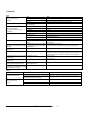
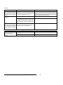
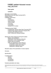
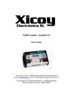
FADEC system-Autostart version
Description of the FADEC.
Users guide.
The FADEC (Full Authority Digital Engine Control) is a total system for the control of a model gas turbine engine. Its
main function is to control and regulate the fuel pump, providing to the turbine engine the necessary amount of fuel for safe and
controlled operation. The FADEC measures the exhaust gas temperature, the relative position of the throttle stick and the rotor
speed. It monitors all of the controls necessary to guarantee that the engine stays between the user defined parameters of
operation, also providing failsafe shutdown of the engine when it has detected any important anomaly. In order to make this
assessment, the FADEC has a rpm sensor, a thermocouple input, a throttle servo input, power connections for the fuel pump, starter,
glow plug, fuel and gas valves and the battery and a digital (RS232) serial port to program and read the data in real -time to a PC.
Contents:
Description of the FADEC.
Description of the Hand Data Terminal (HDT).
Interface RS232
Installation instructions:
ECU
Pump Battery
Radio Receiver
Thermocouple
Fuel pump
Fuel system
R.P.M. sensor
Programming the FADEC
Programming using the Hand Data Terminal (HDT)
Programming using the personal computer (PC)
The measurements made by the FADEC are:
•
•
•
•
•
•
Temperature of the exhaust gas
Pump battery voltage
Width of the throttle pulses from the radio transmitter
Engine rotor RPM
Engine run time.
External analog signal.
All of these measurements can be read into and displayed on the Handheld Data terminal (HDT) that is connected to
the FADEC by a RJ-45 connector, or into a personal computer trough a RS232 adapter. The configuration/setup parameter s are
stored in the FADEC by the terminal of hand or the PC.
Features:
•
•
•
•
•
•
•
•
•
•
•
•
•
•
Starting the turbine engine and tuning the system.
Adjustment of the fuel pump start point.
Engine start-up procedure.
Setup and adjustment of the values for;
Acceleration speed (ramp up delay),
Deceleration (spool down delay),
Stabilization (Stability delay).
Standard values of the parameters in known engines:
Warranty
Specifications
Troubleshooting
Starting
Running
Acceleration
Deceleration
RPM input: Magnetic sensor up to 250.000 R.P.M.
Temperature range up to 1000ºC using a "K" type thermocouple
PWM control of 1024 levels for pump, glow plug and starter motor.
Adjustable power for the starter motor
Build-in electronic brake for the starter motor to help the clutch to disengage.
Blown glow- plug detector
Adjustable glow-plug power
Glow-plug temperature independent of the battery voltage
Adjustable gas off temperature
Adjustable rpm starter switch on and off.
Elapsed engine run timers
Status LED on the unit plus 2 more remote on option
RS232 interface to interface to a PC.
Black box function. Record the engine measures each 0.5sec up to 52 minutes.
Adjusting the paramet ers:
On this software version there are 2 sets of parameters that can be changed.
The "user" parameters are adjustable trough the Data Terminal using normal menus. The "manufacturer" parameters
are accessible by a special procedure and in some software versions, are only accessible by the manufacturers.
The user parameters are:
Autostart parameters and setup
Copyright © Gaspar Espiell. All rights reserved. No part of this document may be reproduced or transmitted in any form without prior
written consent of Gaspar Espiell.
Gaspar Espiell shall not be liable for technical or editorial errors or omission contained herein; nor for incidental or consequential
damages howsoever resulting from the use of this material
•
•
•
•
•
•
•
•
•
•
•
•
Radio throws adjust.
Maximum rpm
Idle RPM
Stop RPM
Minimum temperature
Maximum temperature
Acceleration time
Deceleration time
Stability time
Pump start point
Pump start ramp
Glow plug power
From these parameters, the readings of the engine and the position of the throttle control, the FADEC adjusts the power
to the fuel pump in the following way:
FADEC Autostart User’s Manual. V1.1 24/01/03
1/7
First, the FADEC verifies that the control pulse of the transmitter is cor rect, that is to say, is between the limits set by the
user. If the pulse is not correct, or the pulses are not received during 0.5 seconds, the system assumes that there is a trouble with the
radio link and shuts down the engine (fail safe). During this time of delay, the system assumes that the throttle is at idle and
decelerates the engine to this power.
Once verified that the pulse is correct, the relative position of the throttle stick determined by the limits programmed by
the user is calculated. Thi s calculation gives a value between 0% and 100% that can be read on the HDT or a PC. This value is
transformed into a value of equivalent rotor speed from the values of full power speed and idle speed programmed by the user. For
example, if we programmed a idle speed of 30.000 rpm and a full power speed of 100.000 rpm, this speed will be reached with the
throttle control at 100%. With the throttle stick at 50%, the equivalent speed would be 65.000 rpm (half way between 30Krpm and
100Krpm). This calculated equivalent speed is compared with the one read from the engine and the power to the pump is
corrected/adjusted until reaching the desired speed, in this case 65Krpm.
The speed of the slope of spool up is a parameter programmed by the user. To accelerate the engine the FADEC has
to raise the power to the pump. The system monitors the exhaust temperature, reducing the rate acceleration if the temperature
approaches to the maximum programmed temperature. In case of arriving at this maximum temperature, the s ystem reduces the fuel
flow until restoring the motor within its limits of operation, being able to stop the pump if it can not lower the temperature. With this
system it is guaranteed that the engine accelerates in the minimum time possible without exceeding the max. temperature or speed,
adapting itself to the variations of the engine, room temperature, pump, fuel pressure etc.
With this system, called closed loop, the rotor RPM of the engine tracks linearly with the position of the throttle control,
independently of the type of pump, batteries or engine. This benefit is very useful in multiengine aircraft, since the thrust of the
engines is always in balance.
Aside from the safeguards of speed out of limits, temperature or radio failure, the system als o incorporates two
additional safeguards. First is pump shutdown in case that the temperature of the exhaust is lower than the minimum, protecting the
engine from flooding itself of non-burned fuel in case of flameout. The second is fuel pump shutdown due to a too low rotor speed.
The system stops the fuel pump in case that the rotor speed is less than the programmed stop pressure. This safeguards the engine
from continued running in case that rotor speed is less than that required to self-sustain the engine, or in a rpm sensor failure.
The engine can be started manually (semiautomatic) or full autostart system.
In order to start the engine in manual mode, the user must first raise the transmitter throttle trim and leave the throttle
stick in idle/minimum position. The green Light Emitting Diode (LED) on the FADEC illuminates, indicating the system is "ready for
start". Once in this position, the operator must 1) turn/spin up the engine with the starter motor / blower etc, 2) open the
butane/propane gas, and ignite it. When the FADEC registers an exhaust temperature higher than the programmed start/minimum
temperature and the rotor turning, the LED begins to blink and, 3) the system begins to pump fuel to the motor, raising the fuel pump
power slowly until the idle speed is reached. This final condition is signaled by the system extinguishing the LED. The manual start is
only possible after power -on the unit. If the throttle is cycled, the system enters in AUTO mode, and cannot be started in manual until
it is switched off/on again.
To start the engine automatically, the user should cycle the throttle from idle to full power and back to idle again. In this
moment the start procedure is triggered and the autostart sequence progress until the engine is at idle. The user can abort the start
process by lowering the trim.
In the case that the measured exhaust temperature is higher than the start/minimum programmed temperature, the
throttle stick acts a switch, allowing the starter to be energized and too cool down the engine after a aborted start.
A pump prime system is added. When, in the start phase, the throttle stick is set up to 100% during 5 sec, the pump is
switched on at 25% of power for 1 second maximum. This allows to prime the pump and the fuel tubes before the start.
4. Installation of the FADEC .
Please note that:
•
•
•
•
If the thermocouple connector is connected inverted, the temperature will decrease when heated, and the FADEC will fail in to
recognize the gas ignition.
If the RPM sensor is connected inverted, no RPM will be read.
Use the recommended starter motor and battery. If bigger voltages are used, then the high current from the motor can
damage the ECU. If after a start attempt you feel that the FADEC becomes warm, this is a sign that something is wrong. The
FADEC should be cold all of the time.
The glow plug positive cable is connected to the engine body. This means that the whole turbine is connected to the positive
of the pump battery. Take this on account if you plan to connect the negative in other place.
4.1 FADEC main unit
Because the FADEC is an electronic piece of equipment, the installation in the model aircraft is similar to that of the
radio receiver. It has to be in an accessible location within the airframe, with limited vibration and far from the heat of the engine. Also
because the pump motor uses DC power, that can produce sparks in the collector when operating, it is highly recommended that the
installation of all of the electrical equipment is done as far as possible from the R/C receiver. Keep the power cables at the minimum
possible length and avoid installing the antenna near them. Also anti-spark capacitors must be installed on the pump motor.
4.2 Pump/starter battery.
The FADEC needs for its operation two different power supplies. The first is taken from the radio receiver through the
throttle servo connection and the second is the battery that supplies the pump. Reversing the polarity of the battery causes the
destruction of the semiconductors of the FADEC .
The FADEC can work with pump battery voltages between 1.2v and 15v in manual start mode and from 4,8V to 15 in
autostart mode. The selection of the number of battery elements is due in consideration of the real needs of the ancillary equipment
like starter motor, solenoid valves and pump motor. Use only the recomm ended battery voltage and capacity.
This battery does not need an on/off switch in the airframe since the FADEC has an internal electronic switch, which
disconnects it when the power to the receiver is switched off.
The NiMh batteries are not recommended due at his high internal resistance. Use good quality sintered
fast-charge nicads for the ECU supply with at least 1200mAh, preferably 2000mAh, capacity and charge before each flight.
4.3 Receiver of radio .
The FADEC is connected to the radio receiver like a standard throttle servo, inserted in the channel for the throttle,
receiving the information of the throttle control pulses and the receiver battery supply.
4.4 Thermocouple
The FADEC use a thermocouple of type " K ", apt until 1100ºC. The provided standard thermocouple consists of a wire
of Inconel of 1.5mm of diameter finished in a connector who fits directly on the FADEC. The recommended installation consists of
practising a drill of 1,5 mm in the exhaust nozzle of the engine and inserting the end of the thermocouple so that it be 2mm within the
flow of exhaust gases.
4.5 Fuel system.
Connections:
•
•
•
•
•
•
•
•
•
or inverted. Use the coloured labels on the FADEC body to connect all the connectors in his place. The configurations of the pins
have done in the way that no damage can be produced to the electronics in the case of a bad connection.
Throttle input to the receiver : JR type servo cable.
Propane/butane valve: JR type connector receptacle
Fuel valve: JR type connector receptacle. The central cable is positive and th e two of the sides negative.
RPM sensor: JR type connector receptacle
Thermocouple: JR type connector receptacle
Battery input: Red/black cable
Fuel pump: Red/Green cable
Glow plug: Red/Yellow cable
Starter: Red/Blue cable
Use 6 mm tubes in the suction side of the pump, and 4 mm from the pump to the fuel solenoid valve, and from this one
to the engine.
5. Programming of the FADEC.
Use the recommended parameters for your engine. Some of these parameters are set at factory and can’t be modified
by the user. The programmable parameters are as follows:
*Note: In all power cables the red is the common and positive. This means that all the red cables are connected internally together
and to the positive of the pump/starter battery.
Connect all of the cables in his places. Note that some of the JR type connectors used can be connected in wrong place
FADEC Autostart User’s Manual. V1.1 24/01/03
2/7
FADEC user programable parameters:
The values displayed are:
Parameter
Full speed
RPM
Idle RPM
Function
Sets the maximum rotor speed that will be reached by the engine with the throttle control at
100%
Sets the rotor speed at idle
Range
0-250.000 RPM.
Xxxx
0-250.000 RPM.
Yy
Stop RPM
Sets the minimum rotor speed which the engine can run. If the speed is lower, the FADEC will
shut down the engine.
Minimum temperature at which the engine can work. In the start phase, the FADEC will begin to
provide power to the fuel pump. In the running/operating phase, it will stop the engine if the
temperature is less this setting.
Maximum Temperature of operation of the engine. The FADEC will try to maintain the EGT
temperature below this value, finally stopping the motor in case it can't be obtaine d
This parameter allows the adjustment of the time of acceleration ramp / delay of the engine. The
higher the value, the more slowly the engine will respond. The total time of acceleration is not
fixed, since it depends on other parameters as they depend on the present temperature and
speed.
Just as the acceleration delay, this parameter defines the time required for deceleration. This
parameter must be increased if the motor tends to flame out when going abruptly from
maximum power to the idle.
This parameter allows stabilising the power once the system has arrived at the value set by the
throttle control. The value must be increased if the power setting is not stable.
This parameter sets the minimum pump voltage where the pump just begins to turn. This value
is dependant on the voltage of the battery and the pump motor.
Sets the rate of increase of fuel flow during the start-up phase. The higher the value, more
quickly the motor will accelerate up to idle. High values along with a under -powered starter can
cause the engine to blow flames out the exhaust.(Wet/Hot starts)
Low values imply a slow starting.
This parameter sets up the throttle limits at the three key points. Stop, Idle and maximum
power.
Sets the brightness of the glow plug.
0-250.000 RPM.
zz.z
w.w
Start/Minimum
Temperature
Max.
Temperature
Acceleration
delay
Deceleration
delay
Stability delay
Pump start
point
Pump Start
Ramp
Stick travel
adjusts.
Glow Plug
power
0-999 ºC
Following screens:
0-999 ºC
0-255
1-255
u
w
s
w
T
w
w
w
=
P
y
w
y
z
y
z
º
z
L
p
o
x
w
.
e
x
r
x
S
p
e
E
D
The expression x.xx indicates the value stored in the FADEC. In order to change it is necessary it to use the right
buttons " Data Up " to increase the value and " Data Down " to decrease it.
The programming of all the data is made sequentially, changing to the next screen using the button " Menu Up". The
programming of the radio transmitter is a special case and needs a different procedure, described next.
Programming of the radio transmitter setting with the HDT.
0-255
For the programming of the radio you need to have the FADEC and the HDT working with the radio receiver with its
battery pack and the transmitter. It is not necessary to install the thermocouple, the pump or RPM sensor.
Preparation and verification of the transmitter.
Screen 1 always appears first when starting (switched on/off) the HDT and shows the main primary parameters of operation of the
engine. The representation of the screen is as follows:
t
w
l
0-255
Screen 1
a
m
U
0-255
The HDT has a LCD with 16 characters x 2 rows and four buttons which allow you to move through the various menus
and to change the data settings in each menu page. The presentation of data has been organized in screens. The first two displays
the engine status readings in real time and the following screens allow you to modify the operating parameters as above table. All of
the parameters can be modified while the engine is running, so it is easy to tune the engine without having to start it again to test the
new settings. Both left buttons allow you to move through the different screens in an ascending mode (Menu Up) or descending
mode (Menu Down). Both right buttons allow you to change the data in increasing value (Up Data) or decreasing value (Down Data).
t
p
The following screens have all the same structure, except they are used of the programming of the FADEC control
parameters, and allow you to change the operating parameters, even with the engine running . As an example the first next screen
that appears, is the maximum speed.
F
5.1 Programming the FADEC with the terminal of data (HDT).
S
R
Duration of the pulse of control received from the receiver. This it is a absolute value read from the radio transmitter. The
usual values are between minimum 800-1000µS and 2000-2200 µS maximum.
Calculated value relative to the position of the throttle control. The FADEC uses the programmed values of maximum and
minimum along with the real reading to calculate the relative power setting for the control of the fuel pump.
Voltage of the battery supplying fuel pump
Software version
C
%
The values displayed are:
Status
A eight character word indicating the state of the FADEC. (Ready, Fuel Ramp,...)
Yyy
Temperature of exhaust in ºC
Wwwwww
Speed (R.p.m.)
Zzz
Power of the pump. This reading allows to know % the applied voltage the pump, and therefore, its relative
power.
Screen 2
Screen 2 shows the secondary parameters of operation, they are the information received from the radio transmitter and the voltage
of the battery.
The transmitter must not have programmed any reduction of throw, trim, slow movement, the center value
or the linearity modified. In case of doubt it is recommended to connect a servo to verify that the movement is correct from end to end
and fast. Once the transmitter is OK, connect the FADEC and by means of the key " Menu Up " change to screen 2. With the trim
and stick of the tr ansmitter raised (Full power) the reading of "Pulse = xxxx” must be between 1900-2200. With stick and the trim
lowered, the reading must be between 800 and 1000. In case that the readings are inverted, like in some Futaba transmitters, it is
necessary to change the sense of the movement in the transmitter. (Servo reverse). If the reading does not arrive at these values
means that the transmitter has some function of limitation of throw applied to the throttle channel. Once verified the transmitter, the
FADEC can be programmed. In order to do it, the HDT has 4 screens.
Move to the screen 'Transmitter programming'. This first menu is only informative and it warns us of the entrance in the
screens of programming of the throttle control. Press the button 'Data Up' to enter in the programming menus. Next it appears the
screen of programming the full throttle position. In order to program this parameter locate the trim and stick in the superior position.
Once located in this position, push the button "Data Up". At this moment the FADEC will record the received order of the radio as the
position of full power and, in the HDT, the following phase of adjustment is shown. If it is not wanted to modify this adjustment, is
enough with pushing the key "Menu up". This also causes the change of screen but the throw is not programmed.
The following screen allows programming the lower limit (Stop). In order to do it is enough with locating the trim and
stick to the minimum and push the button "Data Up ". Also in this case pushing the button " Menu up " will cause the change of
screen without varying the previous adjustment.
The last screen of adjustment of the transmitter is the position of the trim that will correspond to the idle of the engine. In
order to make this adjustment it is sufficient with locate the stick to the minimum and the trim to maximum and push the button " Data
Up”. Just as in the previous adjustments, the button " Menu up " will cause the change of screen without varying the last recorded
adjustment.
Once finished the programming of the transmitter, this can be verified by means of the second screen of the HDT.
To the right of the value of the received pulse of the transmitter appears a value from the 0 to 100%. This value must
correspond to the relative position of the throttle stick, corresponding 0% to stick and the trim to the minimum and 100% to stick and
trim to the maximum. If it were not arrived at these values, or the limits of the 0 or 100% were reached before arriving stick in the end,
the calibration process is due to repeat.
When the superior and inferior limits are verified, the adjustment of the trim can be verified. This it is made through the green LED
that incorporates the FADEC.
With the FADEC in start mode, that is to say, just star ted, locating the trim and the stick at lower side the LED must be off. When
raising the trim slowly, the LED must lit approximately to half of the throw of the trim. From this point the FADEC considers that the
motor must be running and below this, stopped.
5.2 Radio link failsafe:
P
V
U
B
l
=
s
z
e
z
=
.
X
Z
x
V
x
x
V
µ
e
S
r
w
y
.
y
W
%
The FADEC have a failsafe feature that stop the engine in the case of the radio link failure, but prevents to stop it in the
FADEC Autostart User’s Manual. V1.1 24/01/03
3/7
case of short glitches. This system works in PCM/PPM/IPD systems.
The FADEC calculates the speed of acceleration depending of the exhaust temperature, the current rotor speed and this parameter
(Acceleration Delay), and therefore, it is possible to modify the global time of acceleration modifying it. Higher values mean longer
acceleration times.
PPM systems :
In the case of radio failure (erratic movement of the servos or pulses out of the programmed values window), the
FADEC sets the power to idle during approximately 1 sec. If the radio link is regained in this time, the power goes back to normal, but
if not the system kill the engine.
Time of decelerat ion (Deceleration delay)
For the calculation of the speed of deceleration the FADEC considers the same parameters as in the acceleration,
unless the fixed value is this other parameter. Higher values mean longer times.
PCM /IPD systems:
The user should program the failsafe of these systems to cut the engine (trim low-stick low). In the case that the
receiver have a radio link failure, it will output the failsafe settings. The FADEC will set the power at idl e during 1s after receiving the
stop command, and if during this time the receiver exits from failsafe the engine will go back to the throttle set power. If not, it will be
cut-off. This system allow to fly trough small glitches while retaining the ability to kill the engine in the case of radio failure.
EVER PROGRAM THE FAILSAFE TO KILL THE ENGINE. NEVER FLY A TURBINE PLANE WITH THE FAILSAFE
SET TO “HOLD”.
5.3 Special features
7. Recommended values of the parameters on known engines in Autostart Mode:
Timers
The last screen of the HDT shows the 3 timers included in the FADEC. The first is the total engine time in minutes, the
second the last run time in seconds, and the third is the start/stop cycles counter. These timers can be only cleared by a special PC
software.
Last power-down cause:
The FADEC stores in its internal memory the measures of the engine each 0,5s up to 52 minutes. These measures are
RPM, Temperature, Throttle position, pump power and a external analog input, usually airspeed. These measure only can be
downloaded trough a PC and a RS232 cable, but the user can check trough the HDT the cause of the last power down and the
measures of the engine at the moment when the FADEC cut the engine. This feature is useful to track the cause of a flame out in
flight. After power up, set the trim low and press the “menu down” button. The HDT will show the cause of the last shut down, and the
EGT, RPM and pump power at this moment during 2 sec.
Engine:
Maximum speed:
Idle speed
Stop speed
Maximum temperature
Minimum temperature
Pump:
Battery voltage
Pump start point
Starter type
6.1 Adjustment of the “Pump start point” value.
The FADEC have the ability of to automatically adjust the pump power to start it at the lowest possible speed, independently of the
battery voltage and pump roughness. Also the user have the possibility to adjust the minimum pump power manually.
AUTOpump mode:
The values of “Pump start point” from 0 to 8 are in AUTO mode. This means that the FADEC will adjust itself the pump
power to start it slowly. The recommended value is AUTO+0, that make that the pump start at the minimum possible speed, but it is
possible to start it a faster speed by selecting AUTO+1, AUTO+2 if needed.
Manual mode:
From values from 9 to 255 the power applied to the pump is fixed. It is necessary to test with the selected pump and
battery the right value to allow the pump to turn at the minimum speed.
6.2 Adjustment of the “Pump start ramp” value:
This parameter adjust the speed of the fuel increase during the “Fuel ramp” phase. Higher values mean a faster fuel
flow increase. Increase this value if the engine take too long to arrive to idle, and decrease it if the starts are too hot.
6.3 Adjustment of the values of speed of acceleration (Acceleration delay), deceleration (Deceleration delay),
and stabilization (Stability delay)
Habitually these values do not need adjustment and the recommended values are usef ul to most of the engines, but with the
purpose of being able to use the FADEC with any type of turbine they are included in the parameters adjustable by the user.
KJ66
120.000 Rpm
37.000 Rpm
25.000 Rpm
800ºC
100ºC
Haüsl 28020
6V
Auto+2
Speed400 RACE
4,8V
6
Start Ramp
Aplication
Acceleration delay
Deceleration delay
Stability delay
6. Tuning the system.
Time of acceleration (Acceleration delay)
Stability delay
Once the engine has reached approximately the power corresponding to the value of the throttle setting, the FADEC
adjusts the fuel flow with the purpose of match the exact value of thrust. The speed what the FADEC make this adjustment can be
programmed with this parameter. The habitual values vary between 40 and 60, depending on the time of programmed acceleration /
deceleration, the temperature and the inertia of the whole system including pump, engine, tubes, etc. If a too low time is
programmed, the engine will not become stabilized and will be raising and lowering to the power when correcting the FADEC more
quickly than the response time of the turbine. If the time is very long, the FADEC will take more time to adapt itself to the engine in
case of change in the batter ies, pump, etc.
First Start
50
30
40
JG100
126.000 RPM
32.000 Rpm
20.000 Rpm
800ºC
100ºC
Haüsl 30020
6V
AUTO+2
Speed400 6V
Speed400/4,8VR
6
Test bench
30
30
40
Normal fly
20
30
50
MW54
160.000
45.000
30.000
800ºC
100ºC
Haüsl 28020
6V-7,2V
AUTO+2
Speed300
4
Sport fly
15
15
50
8. Warranty:
The FADEC unit has one- year warranty. This includes only the repair/r eplacement of the main unit and the HDT.
Improper use like polarity reversal, short-circuit or crash damage are not included.
This warranty does not include any damage to the engines, airframes, people, or anything else caused by the FADEC malfunction.
The user must provide an emergency shut-off (i.e. a servo operated cut- off valve) for increased security.
Please read and follow the GTBA code of practice. (http://www.gtba.cnuce.cnr.it/CODE.HTM)
9. Specifications:
Measures:
Temperature sensor
Temperature range:
Temperature resolution:
Temperature accuracy:
R.P.M. range:
R.P.M. resolution:
R.P.M. accuracy:
Pump Battery measure voltage range
Voltage measurement resolution:
Voltage measurements accuracy:
Supply:
Receiver battery voltage:
Receiver battery supply current:
Pump battery voltage:
Pump current:
FADEC Autostart User’s Manual. V1.1 24/01/03
K type thermocouple
0-999 ºC.
2 ºC
2%
0-250.000 R.P.M.
100 R.P.M.
0.05 %
0-15 V
0.1 V
2%
4 to 10V
30 mA.
1.2 to 15 V limits. Use the voltage recommended by the engine manufacturer
6 A Max. Continuous. 50A peak
4/7
•
Remote measures and configuration:
Mechanical measures:
Weight:
Asynchronous serial digital link
54 x 34 x 22 mm.
45 g.
•
Autostart & advanced setup.
•
Other than the operators parameters that are usually set by the users, exist another parameters reserved to manufacturers and
advanced users.
•
•
These parameters are:
•
•
•
•
•
•
•
•
•
•
•
The glow-plug is checked, and if OK, it is powered. After waiting 1 sec, the starter is engaged at reduced power (soft
start) and the gas valve is energized. If the glow test fail, a "Glow Bad" message is displayed, and if the starter fails to
arrive a minimum RPM in 2 seconds, a “start bad” message is issued, and the autostart function aborted.
When the rotor arrives at more than the "ignition max rpm" programmed parameter (default 4000), the starter is
disconnected and the brake applied. At the same time the gas valve is opened and the glow plug powered.
When the RPM are lower than the "ignition min. Rpm" parameter (default 1000), the starter is switched on again to
raise the rotor speed to the "ignition max rpm" and the cycle is repeated.
When the thermocouple register a increase of 50ºC in temperature or it is higher than the “start/minimum temperature”,
that mean that the ignition have occurred, the starter is switched on immediately at reduced power, increasing his
power accordingly to the real rotor rpm. At the same time the pump is switched on, and the fuel valve is opened.
The engine begin to accelerate at the "fuel ramp" values, depending on the real RPM. Once the exhaust temperature
(EGT) arrives at a predefined value (usually 400ºC) the gas valve is closed, and when the RPM arrive at the predefined
"starter off" value, the starter is switched off and the brake applied to it. The engine continues accelerating alone until
the idle RPM are reached.
The user can finish the sequence in any moment, simply setting the trim to "off" position. If the engine was on "running",
a cooling sequence will be triggered, cycling the starter motor until the EGT is below the minimum programmed
temperature.
If the engine is hot (EGT higher than the minimum temperature) at the moment that the user triggers the autostart cycle,
then the FADEC will begin a cooling cycle until the temperature is below the minimum programmed temperature. At this
moment it will continue with the normal autostart cycle if the trim is left in up position.
Temperature calibration
Timers reset
Started reduced power (%) in the ignition phase
Starter RPM window (min and max rpm) in the gas ignition phase
Starter swi tch- off RPM. Speed of the rotor were the starter will be switched-off
Starter switch-on RPM. Speed of the rotor were the starter will be recconected if the fuel ramp phase if the RPM’s decay
below this point.
Gas Switch- off temperature.
Minimum RPM to start. Minimum rpm that the rotor should have after 1,5s of starter switch on. If the rpm are below this limit, a
“bad start” label will appear and the start process aborted. Useful to detect starter/clutch failure.
Starter power at the beginning of the fuel ramp.
Rpm were the starter power is at 100%. Wen the system detects the ignition had occurred, it starts the starter motor at
reduced power and this power is increased during the fuel ramp until arrive at the value of this parameter, that is set at 100%.
This feature allows to use small/ low voltage rated starter motors without the risk of burning them due at too much power in the
low speed phase.
Starter ramps. The rpm range from 0 to idle are divided in 3 sectors by 2 rpm points. In each sector, a defined fuel/time slope
is applied. So the real fuel increase in each rpm range depends on the current rpm, the slope value for this rpm range and the
“pump start ramp” parameter, that is added to the ramp value for each rpm sector. For example, if the rpm poi nts are set to
16.000 and 30.000 RPM, the ramp1 at 3, ramp2 at 1, ramp3 at 4 and the “pump start ramp” at 2, then the real fuel ramp
applied from 0 to 16.000 will be ramp1 + “pump start ramp” = 3+2=5. From 16.000 to 30.000 will be ramp2 + “pump start
ramp” = 1+2=3 and from 30.000 to idle ramp3 + “pump start ramp” = 4+2=6. Adding the “pump start ramp” parameter to all
values allow at the operator to modify the whole start time without modifying the “manufacturer” parameters.
•
•
Programming the manufacturer parameters:
•
•
•
First adjust the “operat or” parameters, specially the radio throws.
Set the trim and stick to “low”. “Trim low” readout should appear.
Switch off and on again the FADEC. Wen the initial screen appear (“FADEC....”) press the “data down” button (located
in the right hand low side) and then the “menu down” (located in the left hand, low side). This should be done quickly,
and before that the normal screen appear.
It will appear a screen with a number of parameter and the data. To change the parameter number use the left hand
button, and to change the data use the right hand buttons.
Raise the stick or reset the FADEC to return to the normal screens
•
•
Caution: The parameters are stored in the same time that are modified, so be careful before to modify any parameter.
The meaning of each parameter is: (These recommended values are for a MW54)
Starting the engine:
Ensure your engine operates correctly before attempting full auto-start operation. You can run the engine using the
Autostart ECU in manual mode, by hand starting the engine (ie with a wand or remote starter) after setting the ECU to “Ready”.
Ensure your starter operates smoothly and without sticking. You should be able to attain at least 15,000rpm cold, and
30,000+rpm during the engine starting
Ensure your glow plug element is well “teased out” to ensure prompt gas ignition.
A restrictor is required to set and control the flow rate of the starter gas. Gas supplies must be gas only, dip-tube liquid
feed types are not suitable. Propane/Butane mixtures work well in temperate climates. Beware of using too much gas in the belief
this will ignite more easily. Keep the maximum gas pressure under 2 bar (25psi) to avoid damage to the sol enoid valves.
Problems lighting the gas are mostly related to plug element exposure, ensure the element is pulled clear so the gas
can really “see” the element. It needs to glow bright yellow for good ignition, so adjust the “glow power” setting in the mai n menu as
required
Always set- up and confirm the operation of your Auto-start installation on the test-stand, before installing into your
model.
The present version of Autostart uses only one channel to all of the engine functions: To trigger the autostart cycle, the
process is as follows:
•
•
•
•
The user raises the trim. "Ready" will appear on the HDT (Hand data terminal) screen when the engine is supposedly to
be to idle. If the trim is on "stop" position, "Trim low" will be read on the HDT. If higher than idle, "StickLo!" will be read.
When "Ready" is displayed, the user raise the stick to full power.
Once at full power, if the stick is left in this position more than 5 seconds, the pump prime function is triggered, and the
pump and fuel valve are energized at the 25% of his power for one second as much. The user can switch off it before
this time by lowering the stick.
When the stick is at idle again, the start sequence begins.
Paramet
er Nr.
Rec.
Value
Keep the magnetic RPM pickup clear of stray magnetic sources such as fuel pump, solenoid valves, glow plug wire, or
servo’s, as the magnetic field generated can upset the rpm reading.
Units
ºC *2
1
2 to 15
7
100
Volts/0.06
16
2
Rpm*1000
17
35
0 to 255
18
4
Rpm*1000
19
2
Rpm*1000
20
6
Sec*2
21
0
Sec
Mnemonic Description
OFFSTEMP Temperature sensor offset calibration. This value is subtracted from the one read on the
FADEC.Changes only are read after reset. Factory set, do not change.
Not Used
LowBat Mininimum battery voltage in start phase. If the battery voltage falls below this value, the start is
aborted and “lowBatt” message displayed. Only in start phase, in runni ng phase the engine is
kept running until the battery is empty. Value= Desired cut voltage multiplied by 100 and divided
by 6.
RPMINICI Minimum safe rpm in the fuel ramp phase. Lower RPM than this value than this will abort the
sequence.
POWERSTA
Starter power in the ignition phase. Real power is full power * this value/255.
RPMIGN
Rpm where the starter is switched off in the ignition phase
RPMSTOGA
Rpm where the starter is reconnected in the ignition phase
Preheating time. Time from when the ignition is detected and the fuel ramp is launched.
FADEC Autostart User’s Manual. V1.1 24/01/03
TEMSTAR
Start sequence maximum time.(not operative in the current release)
5/7
22
100
ºC *4
T_STOP_G
23
30
Rpm*1000
R_STOP_S
24
35
0 to 255
POWSTIR
25
24
Rpm*1000
RPMERAM
26
18
Rpm*1000
RPM1TRA
27
30
Rpm *1000
28
2
29
0
30
0
31
24
Start gas switch off temperature. R eal temperature is this value multiplied by 4.
Starter switch off RPM
Starter power at the beginning of the fuel ramp. Real power is full power * this value/255.
RPM where the starter power arrive at 100%
Rpm*1000
First Rpm point in the fuel ramp. From 0 to this value the RAMP1 value will be applied
RPM2TRA Second Rpm point in the fuel ramp. From the 1st RPM point to this value the
RAMP2 value will be applied. Above this value to idle, RAMP3 will be used.
RAMP1
1st. Fuel ramp. The real value used will be this value added to the "Pump start ramp" value.
RAMP2
2on. Fuel ramp. The real value used will be this value added to the "Pump start ramp" value.
RAMP3
3th Fuel ramp. The real value used will be this value added to the "Pump start ramp" value.
RPMONFU
Rpm where the starter is reconnected in the fuel ramp phase if the rpm fall below this point..
.
FADEC Autostart User’s Manual. V1.1 24/01/03
6/7
10. Troubleshooting:
10.1 Start:
Problem:
When raising the trim of the radio, the LED
is not illuminated
Cause:
FADEC in stop mode after a running.
Bad adjustment of the radio transmitter
Supply failure
-Blown glow plug or disconnected
-Pump battery disconnected.
-Starter motor bad/disconnected
Starter power too low
RPM sensor failure
Starter power too low or ignition rpms set to low
Gas can empty or gas solenoid valve disconnected or blocked
Glow plug brightness too low
After cycling the throttle “Glow bad” message appear
After cycling the throttle nothing happens
and later the “Start bad” message appear
After cycling the throttle the rotor turns b ut later the “Start
bad” message appear
The RPM are cycling but the gas doesn’t ignite.
When the start gas is ignited the “start bad” message appear
When the start gas is ignited, the FADEC does not begin to pump fuel
nor the LED blinks.
When the start gas is ignited the LED of the FADEC begins to blink but
the pump does not work
Excessive fuel flow at the beginning of the starting. Start very hot.
Once the pump is started and the engine is running in fuel, it takes too
much time in arriving to idle
Once the pump is started an the engine is running in fuel, the exhaust
temperature is excessive
Once the pump is started an the engine is running in fuel, the exhaust
temperature is excessive and the engine doesn’t arrive at idle.
When the engine arrives at idle the system changes to automatic
mode, exti nguishing the LED, but the speed is higher than the
programmed , lowering slowly until arriving at idle
10.2 Running:
Problem:
10.2.1
The engine does not reach the maximum power.
Gas tube incor rectly set inside the engine
Too much gas. Mix too rich to ignite
The starter failed to have the minimum RPM to continue the
sequence.
The temperature read by the FADEC is lower to the programmed
start temperature due at that the start gas flow is insufficient to
reach start the temperature.
Adjustment of the pump start point defective.
Adjustment of the pump start point defective.
Solution:
Switch off an then on again the FADEC.
Program the parameters of the radio and verify them
Verify the voltage of the batteries. In case that it not work, verify connections, switch, etc.
Check glow plug and battery
Check starter
Check starter power settings.
Check RPM
Check the autostart parameters
Check the gas coming to the engine
Check/adjust glow plug power. The glow should have at least 2 filament turns pulled out, and with high brightness. Check
with a butane lighter the correct brightness.
Ask the engine manufacturer for correct location.
Reduce the gas flow, use only butane mix trough a 0,3mm restrictor
-Check the RPMINICI value on the autostart parameters
-Raise the starter power.
Check the exhaust temperature with the hand terminal.
-Increase the gas flow, reduce the power of the starter in this phas e or lower the programmed start temperature.
Repeat the adjustment of Pump start point and verify the operation of the pump. Adjust the parameter #20 of the submenu
The fuel Start Ramp value is too low.
Repeat the adjustment of Pump start poin.Verify the operation of the pump. It must start smoothly and turn slowly. Do the
test by disconnecting the fuel line from the engine and trigger a autostart squence. Check the fuel flow to check it in real
conditions. Fine tune the “pump start point” if necessary to have the lowest flow and that the pu mp start each time.
Raise the “ start ramp” value.
The fuel Start Ramp value is too high or weak starter motor
Lower the “ start ramp” value.
Too low top RPM of the starter motor and it cannot push the
engine to self above to self sustain.
The fuel Start Ramp value is too high.
Change starter, check the clutch for friction, use a higher voltage battery.
Lower the “ start ramp” value.
Cause:
Maximum speed badly fit.
Battery of the pump empty or with too low cells, defective or insufficient pump, defective
plumbing, including the fuel injectors inside the turbine obstructed.
Solution:
Verify the Maximum speed and readjust it.
Verify the indicator of power of the pump in the HDT. If it indicates 1000, check the pump, battery, tubes...
Stability delay too low.
Increase the “Stability delay”. With a value of 50 the engine must run without problems.
10.2.2
Instability of the power at medium and
and low power.
FADEC Autostart User’s Manual. V1.1 24/01/03
7/7
10.3 Acceleration:
Problem:
10.3.1
When changing quickly the throttle from idle to full power,
the engine accelerates quickly until an intermediate point
and later the power raises slowly until arriving at the
maximum power.
10.3.2
Too slow acceleration
10.3.3
Acceleration does not uniform. When accelerating quickly
the engine from idle to the maximum, this accelerates
quickly to an intermediate point in which it becomes
stabilized during a second, raising to maximum power
next.
10.4 Deceleration:
Problem:
10.4.1
Extinguished of the engine. When lowering
quickly the throttle from maximum power to idle, the
engine is stopped.
Cause:
An external change to the FADEC in the circuit of fuel supply has taken place from the last
normal start/stop cycle, as it can be the change of pump, change of the number of
elements of the battery, or change in the engine. The internall y stored data do not agree
with the real ones, reason why the FADEC must find the new values.
The value of acceleration delay is excessive.
Solution:
Wait until the engine accelerates to the maximum power. Then lower the power slowly with the throttle stick
until idle and raise it slowly until the maximum power 2 or 3 times with the intention of which the FADEC can
find the data of all the margin of operation. Each movement must last like 10s minimum. Once this is done,
verify that with fast movements of stick the engine responds immediately. Stop the engine lowering the trim of
the radio so that the FADEC keeps the new data in the permanent memory.
Lower the delay. The habitual value oscillates between 20 and 60 in a standard engine.
The exhaust temperature is very high or the maximum programmed temperature is too
low. The FADEC modifies the time of acceleration on the basis of the margin of
temperature between the maximum and the current one. If this difference is small, the
acceleration will be slower since a greater risk exists of exceeding the maximum
temperature.
The value of acceleration delay is too low. The FADEC tries to accelerate the engine more
quickly than it allows, causing that the temperature raises excessively, moment in which
the FADEC reduces the fuel flow to maintain the temperature controlled.
Verify the adjustment Maximum temperature, and check the exhaust temperature..
Cause:
The value of the deceleration delay too low. In some engines the abrupt reduction of the
fuel flow causes a flame out.
Solution:
Increase the value of the “Deceleration delay" parameter.
Increase the value of the acceleration delay until the acceleration is fast and without steps.
FADEC Autostart User’s Manual. V1.1 24/01/03
8/7