1
Projector
CP-X4021N/CP-X5021N/
CP-WX4021N
User's Manual (detailed)
Network Guide
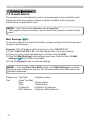
Thank you for purchasing this product.
This manual is intended to explain only the network function. For proper use of this
product, please refer to this manual and the other manuals for this product.
WARNING ►Before using this product, be sure to read all manuals for this
product. After reading them, store them in a safe place for future reference.
Features
This projector has the network function that brings you the following main features.
Network Presentation : allows the projector to project computer images transmitted
through a network. (37)
Web Control : allows you to monitor and control the projector through a network from a
computer. (45)
My Image : allows the projector to store up to four still images and project them. (70)
Messenger : allows the projector to display text sent from a computer through a network.
(72)
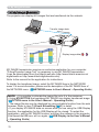
Network Bridge : allows you to control an external device through the projector from a
computer. (74)
NOTE • The information in this manual is subject to change without notice.
• The manufacturer assumes no responsibility for any errors that may appear in
this manual.
• The reproduction, transfer or copy of all or any part of this document is not
permitted without express written consent.
Trademark acknowledgment
• Microsoft®, Internet Explorer®, Windows®, Windows Vista® and Aero® are registered
trademarks of Microsoft Corporation in the U.S. and/or other countries.
• Pentium® is a registered trademark of Intel Corporation.
• JavaScript® is a registered trademark of Sun Microsystems, Inc.
• HDMI, the HDMI logo and High-Definition Multimedia Interface are trademarks or
registered trademarks of HDMI Licensing LLC in the United States and other countries.
• Trademark PJLink is a trademark applied for trademark rights in
Japan, the United States of America and other countries and areas.
All other trademarks are the properties of their respective owners.
1
Contents
Contents
1. Connection to the Network ...................................................... 4
1.1 System requirements ................................................................................. 4
1.1.1 Required equipment preparation ..................................................................................... 4
1.1.2 Hardware and software requirement for computer .......................................................... 4
1.2 Installing the “LiveViewer” .......................................................................... 6
1.2.1 Installing the “LiveViewer” ................................................................................................ 6
1.2.2 Updating the “LiveViewer” ................................................................................................ 7
1.3 Process to connect the network ................................................................. 8
1.3.1 Process overview ............................................................................................................. 8
1.3.2 Starting the “LiveViewer” .................................................................................................. 9
1.4 Selecting the network connection mode ................................................... 10
1.4.1 Selecting either the wireless LAN or wired LAN ............................................................ 10
1.4.2 Selecting My Connection ............................................................................................... 12
1.5 Selecting the network connection method ................................................ 14
1.5.1 Passcode connection ..................................................................................................... 15
1.6 Manual Configuration ............................................................................... 23
1.6.1 Profile connection .......................................................................................................... 23
1.6.2 History connection ......................................................................................................... 24
1.7 Configuring the network settings manually ............................................... 25
1.8 Confirming the connection to your destination ......................................... 30
1.8.1 Connection and transmission ......................................................................................... 30
1.8.2 Connection error ............................................................................................................ 32
1.9 Profile data ............................................................................................... 33
1.9.1 Outline of Profile data .................................................................................................... 33
1.9.2 Making Profile data ........................................................................................................ 33
1.9.3 Editing Profile data ......................................................................................................... 34
1.9.4 Registering My Connection ............................................................................................ 35
2. Network Presentation ............................................................. 37
2.1 Using the “LiveViewer” ............................................................................. 37
2.1.1 Main menu and Operating buttons ................................................................................. 37
2.1.2 Displaying the status ...................................................................................................... 39
2.1.3 Switching the display mode ........................................................................................... 40
2.1.4 Option menu .................................................................................................................. 41
2.2 Starting the Network Presentation ............................................................ 43
2.2.1 Display mode ................................................................................................................. 43
2.2.2 Presenter mode ............................................................................................................. 44
2.2.3 Display User Name ........................................................................................................ 44
2
Contents
3. Web Control ............................................................................ 45
3.1 Logon .......................................................................................................
3.2 Network Information .................................................................................
3.3 Network Settings ......................................................................................
3.4 Port Settings .............................................................................................
3.5 Mail Settings .............................................................................................
3.6 Alert Settings ............................................................................................
3.7 Schedule Settings ....................................................................................
3.8 Date/Time Settings ...................................................................................
3.9 Security Settings ......................................................................................
3.10 Projector Control ....................................................................................
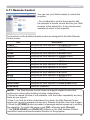
3.11 Remote Control .......................................................................................
3.12 Projector Status ......................................................................................
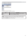
3.13 Network Restart ......................................................................................
46
48
49
50
52
53
55
58
60
61
67
68
69
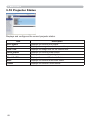
4. My Image Function ................................................................. 70
5. Messeger Function ................................................................. 72
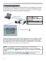
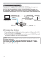
6. Network Bridge Function ....................................................... 74
6.1 Connecting devices ..................................................................................
6.2 Communication setup ...............................................................................
6.3 Communication port .................................................................................
6.4 Transmission method ...............................................................................
74
75
75
76
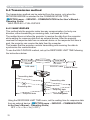
6.4.1 HALF-DUPLEX .............................................................................................................. 76
6.4.2 FULL-DUPLEX ............................................................................................................... 77
7. Other Functions ...................................................................... 78
7.1 E-mail Alerts .............................................................................................
7.2 Projector Management using SNMP ........................................................
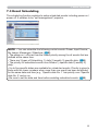
7.3 Event Scheduling .....................................................................................
7.4 Command Control via the Network ..........................................................
78
80
81
84
8. Troubleshooting ..................................................................... 89
9. Warranty and after-sales service .......................................... 92
3
1. Connection to the network
1. Connection to the network
1.1 System requirements
1.1.1 Required equipment preparation
The following equipments are required to connect the projector to your computer
through the network.
Projector
LAN cable (to connect the projector to a network): CAT-5 or greater
Computer (minimum 1 set): equipped with the network feature
(100Base-TX or 10Base-T)
1.1.2 Hardware and software requirement for computer
The “LiveViewer” software needs to be installed on all the computers to connect
to the projector through a network. To use the “LiveViewer” your computer needs
to meet the following requirements.
OS: One of the following.
Windows ® XP Home Edition /Professional Edition (32 bit version only)
Windows Vista ® Home Basic /Home Premium /Business /Ultimate /Enterprise (32
bit version only)
Windows ® 7 Starter /Home Basic /Home Premium /Professional /Ultimate /
Enterprise (32 bit version only)
CPU: Pentium 4 (2.8 GHz or higher)
Graphic card: 16 bit, XGA or higher
* When using the “LiveViewer” it is recommended that the display resolution of
your computer is set to 1024 x 768.
Memory: 512 MB or higher
Hard disk space: 100 MB or higher
Web browser: Internet Explorer ® 6.0 or higher
CD-ROM drive
NOTE • The network communication control is disabled while the projector is
in standby mode if the STANDBY MODE item is set to SAVING. Please connect
the network communication to the projector after setting the STANDBY MODE
to NORMAL. (SETUP menu in the User’s Manual – Operating Guide)
• You can get the latest version of the “LiveViewer” and the latest information
for this product from our website. (7)
• Depending on the specification of your computer, the computer may slow
down due to high CPU usage when the “LiveViewer” is running.
• The “LiveViewer” does not work on Windows Vista® that is not updated to
Service Pack 1 or later. Please install the latest Service Pack on your Windows
Vista®.
4
1. Connection to the network
1.1 System requirements (continued)
NOTE • Referring to the manual of your computer or Windows, select the
following or a smaller display resolution for the computer.
CP-X4021N, CP-X5021N: 1024 x 768 (XGA)
CP-WX4021N: 1280 x 800
When a resolution larger than the specified resolution is selected, the projector
will convert and display in the specified resolution, and the display speed
may become faster. If your computer does not support the display resolution
specified above, a smaller resolution that is the largest among the resolutions
that are supported by the computer will be selected.
• Images might not been transmitted, caused by OS version or the driver
software for Network Adapter on your computers. It is highly recommended that
OS and the driver should be updated to the latest.
5
1. Connection to the network
1.2 Installing the “LiveViewer”
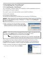
1.2.1 Installing the “LiveViewer”
The “LiveViewer” software needs to be installed on all the computers to connect
to the projector through a network.
You need to log in as an administrator user to install the software.
1) Turn on the computer.
2) Shut down all applications.
3) Insert the accompanying CD-ROM into the computer's CD-ROM drive.
NOTE • After sequence 3), the User Account Control (UAC) dialog will appear
(if you are using Windows Vista or Windows ® 7). Please click the [Allow] to
continue installation.
4) After a moment, the Choose Setup Language
dialog will appear as shown on the right. Select
what you like to use in the list, and click the [OK].
NOTE • If the Choose Setup Language dialog doesn't appear, proceed as follows:
(1) Click on the [Start] button on the toolbar and select the “Run”.
(2) Enter E:\software\setup.exe and then press the [OK].
If your CD-ROM drive is not drive E on your computer, you will need to
replace E with the correct drive letter assigned to your CD-ROM drive.
If the software has been already installed, Uninstallation will be done. Click
the [Cancel] button, then uninstallation will be canceled. If you uninstalled the
software by miss-operation, please re-install the software from first procedure.
5) After a moment, the Welcome dialog will appear
as shown on the right. Press the [Next].
6
1. Connection to the network
1.2 Installing the “LiveViewer” (continued)
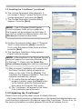
6) The License Agreement dialog appears. If
you accept it, select “I accept the terms of the
license agreement” and press the [Next].
7) The Choose Destination Location dialog
appears. Press the [Next].
NOTE • The C:\Program Files\Projector
Tools\LiveViewer folder will be created and
the program will be installed into that folder. If
you wish to install to a different folder, click the
[Browse] and select another folder.
8) Confirm the program folder name. If “Projector
Tools” is okay, press the [Next] to continue.
If not, enter the desired folder name and then
press the [Next].
9) The Hardware Installation dialog appears.
Press Continue Anyway.
NOTE • After sequence 8), the Windows Security
dialog will appear if you are using Windows Vista
or Windows ® 7. Please click the [Install this
driver software anyway] and continue installation.
10) After a moment, installation will complete and
the Setup Complete dialog will appear as
shown on the right. Click the [Finish]. This
completes the software installation. Then your
computer automatically restarts.
(1) To confirm that the software has been
properly installed, press the [Start] button
on the toolbar, select All Programs and
then select the Projector Tools folder.
(2) The “LiveViewer” will appear in that folder
if the installation was successful.
1.2.2 Updating the “LiveViewer”
Please check and get the latest version at Hitachi Web site.
http://www.hitachi-america.us/digitalmedia or http://www.hitachidigitalmedia.com
Some functions explained in this manual require the “LiveViewer” Version 4.xx. (In
the version information a number between 00 and 99 will replace the xx.)
7
1. Connection to the network
1.3 Process to connect the network
Before connecting your computer and projector via a network, make sure that the
LAN port is selected as the input source on the projector. (Operating in the
User’s Manual – Operating Guide) Otherwise a connection cannot be established.
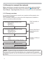
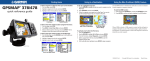
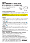
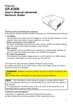
1.3.1 Process overview
An overview of the process to connect your computer and the projector via a
network is shown below.
The “LiveViewer” allows you to skip some of the steps below to establish a
network connection quickly and easily.
q Selecting the network connection mode
- Wireless LAN
- Wired LAN
- My Connection
If My Connection is
selected
w Selecting the network connection method
- Enter PassCode
- Configure Manually
- Select From List
If Enter PassCode or
Select From List is
selected
e Manual configuration
- Profile
- History
- Configure Network Settings Manually
If Profile or History is
selected
r Configuring the network settings manually
t Confirming the connection to your destination
NOTE • Wireless LAN can be selected only when an access point to convert
wireless LAN to wired LAN exists between your computer and the projector.
• Up to 30 computers can be simultaneously connected to the projector through
a network.
8
1. Connection to the network
1.3 Process to connect the network (continued)
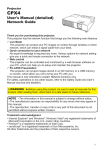
1.3.2 Starting the “LiveViewer”
Start the “LiveViewer” in your computer, taking one of the followings.
1) Double click the “LiveViewer” icon on the Desktop in your computer
2) Select “Start” → “All Programs” → “Projector Tools” → “LiveViewer” on
Windows menu.
Then, proceed to item 1.4 Selecting the network connection mode. (10)
9
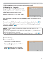
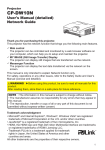
1. Connection to the network
1.4 Selecting the network connection mode
After starting the “LiveViewer”, the “Select the
Network Connection” screen comes up.
Select the network connection that you would like
to use. There are 3 options in the menu.
• Wireless LAN
• Wired LAN
• My Connection
If you select either the wireless LAN or wired LAN, proceed to item 1.4.1 Selecting either
the wireless LAN or wired LAN. (below)
If you select My Connection, jump to item 1.4.2 Selecting My Connection. (12)
NOTE • This dialog will not be displayed if the computer has just one network adapter
and no My Connection is registered. Proceed to item 1.5 Selecting the network
connection method. (14)
• Select Wireless LAN only when you connect the computer and the access point via
wireless network and connect the access point and the projector via wired network,
since the projector doesn't have wireless LAN function.
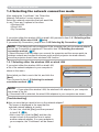
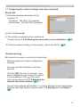
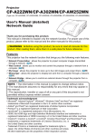
1.4.1 Selecting either the wireless LAN or wired LAN
If you select either the wireless LAN or wired LAN,
a list of the network adapters in your computer is
shown in the menu.
Select what you like to use in the list, and click the
[Next].
Then, proceed to item 1.5 Selecting the network
connection method. (14)
NOTE • If you select the wireless LAN, the wireless LAN adapters in your computer
are shown in the list.
• If the wired LAN is selected, the wired LAN adapters in your computer are shown.
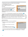
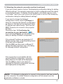
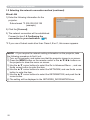
[Troubleshooting]
Are you sure that you want to turn on the network adapter?
The screen is displayed in the case that the
selected network adapter is invalid.
• To turn it on, click the [Yes], and then proceed
to item 1.5. (14)
• Not to turn it on, click the [No], and then the
screen is back to the previous one to select
another network adapter. If no more adapter in
your computer, the “LiveViewer” will be closed.
10
1. Connection to the network
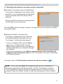
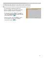
1.4 Selecting the network connection mode (continued)
A network connection was not established.
The screen is displayed in the case that the
projector is not connected with a LAN cable
to your computer when the wired LAN is
selected.
Be sure that the projector is connected with
a LAN cable to your computer.
Click the [OK], then the screen is back to the previous one to select the network
connection mode.
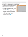
Windows firewall is enabled (On).
The screen is displayed in the case that
the firewall setting is activated, and the
“LiveViewer” is blocked by the firewall.
• To turn it disabled (Off), click the [Yes].
• Not to turn it disabled (Off), click the
[No], but the projector may not be able to
communicate with your computer through
the network.
• If you put a check mark in the [Allow communication with LiveViewer by
adding it to the Exceptions list] box, the “LiveViewer” will never be blocked
by Windows firewall.
Proceed to item 1.5 Selecting the network connection method. (14)
NOTE • If you click the [Yes], the network access by the “LiveViewer” is
temporally permitted by Windows firewall, until the “LiveViewer” is closed.
• If any application software having the firewall function is installed into you
computer, make the firewall function invalid with following the user’s manual.
11
1. Connection to the network
1.4 Selecting the network connection mode (continued)
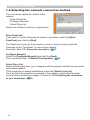
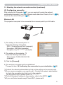
1.4.2 Selecting My Connection
Select the [My Connection] and click the
[Connect].
If you select the My Connection, the computer
is connected to the projector through the
network by using the profile data that is preassigned to My Connection. (35)
When you select the My Connection, the
computer immediately starts the connection to
the projector.
Proceed to item 1.8 Confirming the connection to your destination. (30)
NOTE • If the DHCP is set on in the projector, the network connection
between the projector and computer may not be established since IP address
may be varied. If you like to use the My Connection, set the DHCP off in the
projector.
• If no profile data is assigned to the My Connection, it can’t be used.
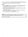
[Troubleshooting]
A network connection could not be established.
Windows prevented network configuration
changes.
You may log in the Windows under User
authority.
Click the [OK] to return to the screen to
select the network connection mode. (10)
Consult to the network administrator and log in again under the Administrator
authority. After that, please resume at item 1.3.2 Starting the “LiveViewer”.
(9)
12
1. Connection to the network
1.4 Selecting the network connection mode (continued)
Are you sure you want to connect the selected projector?
The message is appeared when the
wireless adapter you selected is already
used for another network connection.
• To connect, click the [Yes]. Proceed to
item 1.8 Confirming the connection to
your destination. (30)
• Not to connect, click the [No] to return
to the screen to select the network
connection mode. (10)
13
1. Connection to the network
1.5 Selecting the network connection method
There are some options to connect to the
network.
• Enter PassCode
• Configure Manually
• Select From List
Select one of them to meet your requirement.
Enter PassCode
If you want to use the Passcode for network connection, select the [Enter
PassCode] and click the [Next].
The Passcode is given by the projector on screen. And you simply input the
Passcode to the “LiveViewer” to connect the network.
Proceed to item 1.5.1 Passcode connection. (15)
Configure Manually
Select the [Configure Manually] and click the [Next].
Then, proceed to item 1.6 Manual Configuration. (23)
Select From List
Before selecting this item, your computer and the projectors need to be connected
to the same network.
If the connection is already established, select the [Select From List].
From the list of the projectors connected to the network, select which projector
you would like to send your images. Proceed to 1.8 Confirming the connection
to your destination. (30)
14
1. Connection to the network
1.5 Selecting the network connection method (continued)
1.5.1 Passcode connection
The unique Passcode system brings you very quick and simple connection to the
network.
The Passcode is a code that expresses the network setting in the projector. If you
input the code in the “LiveViewer” in your computer, the network setting in the projector
and computer can be matched and the connection will be established immediately.
The section is intended to explain how to use the Passcode.
(1) Getting the Passcode
The Passcode is 12-digit code consisting of alphanumeric characters (“1-9” and
“A-Z”).
Example: PASSCODE 1234-5678-9ABC
The Passcode is given on the projector when the LAN port is selected as input
source.
NOTE • The Passcode system does not work under the condition below. If
such is the case, establish the connection manually.
1) Subnet mask is not Class A or B or C.
The Passcode system accepts Class A, B and C only.
Class A:(255.0.0.0), ClassB:(255.255.0.0), Class C:(255.255.255.0)
There are two methods to get the Passcode from the projector
Method 1
1) Turn on the projector, and make sure that the projector image is on screen.
2) Press the COMPUTER button on the remote control or INPUT button on the
projector to select the LAN as input port.
If there is no signal on the LAN port, you can find the Passcode on screen.
15
1. Connection to the network
1.5 Selecting the network connection method (continued)
Method 2
1) Turn on the projector, and make sure that the projector image is on screen.
2) Press the MENU button on the remote control or the ▲/▼/◄/► buttons on
the projector to show the menu on screen.
3) Use the ▲/▼ cursor buttons to select the Go to Advanced Menu..., and use
the ► cursor button to enter the item.
4) Use the ▲/▼ cursor buttons to select the NETWORK, and use the ► cursor
button to enter the item.
5) Use the ▲/▼ cursor buttons to select the INFORMATION, and use the ►
cursor button to display the INFORMATION.
6) The Passcode appears in the INFORMATION window.
NOTE • Take the method 2 when you project your computer image by the
“LiveViewer”, or when the LAN port is not selected as input source.
• If no communication between the projector and computer in 5 minutes, the
Passcode will be changed.
16
1. Connection to the network
1.5 Selecting the network connection method (continued)
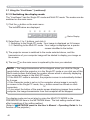
(2) Entering the Passcode
If you select [Enter PassCode] at item 1.5,
the “Please enter the PassCode” screen is
displayed. Please enter the Passcode divided
4-digit each in 3 boxes (total 12-digit).
Example PASSCODE: 1234 - 5678 - 9ABC
After entering the Passcode, click the [Connect] to start the connection to the
projector.
Proceed to item 1.8 Confirming the connection to your destination. (30)
If you click the [Back], the screen is back to item 1.5 Selecting the network
connection method. (14)
NOTE • When entering the Passcode, capital and small letters are not
distinguished.
• If you are using a Subnet mask other than Class A, B or C, you will have to
establish the connection manually.
If the manual setting screen is displayed, please follow item 1.5.1 (3). (21)
[Troubleshooting]
Incorrect PassCode.
The incorrect Passcode was input.
Click the [Back] to return to the “Please
enter the PassCode” screen.
Check the PassCode on the projector
screen (15) and enter the code again.
17
1. Connection to the network
1.5 Selecting the network connection method (continued)
A network connection could not be established.
Windows prevented network configuration
changes.
You may log in the Windows under User
authority.
Click the [OK], then the “LiveViewer” main
menu is displayed even though the network
on the main and
is not established. Click
go back to item 1.5 Selecting the network
connection method. (14)
Consult to the network administrator. Log in the Windows under Administrator
authority. After that, please resume at item 1.3.2 Starting the “LiveViewer”.
(9)
If you need to add a Network configuration on your computer to connect to the
projector.
This dialog will be displayed when you
need to add a Network configuration on
your computer to connect to the projector.
Confirm with your network administrator if
the Network configuration displayed on the
dialog is OK, and then click the [Yes].
Click the [NO], then the “LiveViewer” main menu is displayed even though the
on the main menu and go back to item 1.5
network is not established. Click
Selecting the network connection method. (14)
18
1. Connection to the network
1.5 Selecting the network connection method (continued)
If you put a check mark in the box “Not displaying confirmation dialog for adding
Network settings”, the projector memorizes current configuration and this dialog
is not displayed again. To display this dialog again, click Option
icon in the
“LiveViewer” main menu and remove the check mark in the box “Not displaying
confirmation dialog for adding Network settings”.
If you want to change the Network
configuration to add, click the [Change]. A
dialog for changing the Network configuration
as shown to the right will be displayed. Enter
IP address and subnet mask , then click the
[OK]. Procedure to connect to the projector
will start.
Proceed to item 1.8 Confirming the
connection to your destination. (30)
If you click the [Cancel], you will return to the
dialog for adding a Network configuration.
If the entered IP address and projector's IP
address are the same, a warning dialog shown
to the right will be displayed.
Click the [OK], and then enter a different IP
address from the projector's one in the dialog
for changing Network configuration.
If the connection is not available with the
entered Network configuration, a warning
dialog shown to the right will be displayed.
Click the [OK] to return to the dialog for
changing the Network configuration, and then
enter appropriate configuration.
NOTE • If a Network configuration to connect to the projector has been added
on the computer, the added Network configuration will be erased once the
application software is closed.
19
1. Connection to the network
1.5 Selecting the network connection method (continued)
Are you sure you want to connect the selected projector?
The message is appeared when the wireless
adapter you selected is already used for
another network connection.
• To connect, click the [Yes]. Proceed to item
1.8 Confirming the connection to your
destination. (30)
• Not to connect, click the [No] then the
“LiveViewer” main menu is displayed even
though the network is not established.
on the main menu to go back
Click
to item 1.5 Selecting the network
connection method. (14)
20
1. Connection to the network
1.5 Selecting the network connection method (continued)
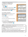
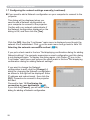
(3) Configuring manually
After entering the Passcode (17), you are required to enter the network
configuration manually if you use a Subnet mask other than Class A, B or C. (15)
If you use the wired LAN, go to (22).
Wireless LAN
The projector is required to be connected to an access point by a LAN cable.
1) The setting on the access point. *1
Enter the following information.
SSID : WirelessAccessPoint (example)
Encryption: WEP64bit (example)
Encryption key *2: ********** (example)
2) The setting on the projector. *3
Enter the following information.
Subnet mask *4: 255.255.255.128
(example)
3) Click the [Connect].
4) The wireless connection will be established.
Proceed to item 1.8 Confirming the connection to your destination. (30)
*1 Contact the network administrator to find out the setting on the access point.
*2 If you use an encryption, you need to set it. Contact the network administrator
to check the encryption key that is set in the projector.
The encryption key is always shown as “**********”.
*3 To find the network setting on the projector, refer to the NOTE. (22)
*4 If you use Subnet mask except Class A/B/C, please set it.
21
1. Connection to the network
1.5 Selecting the network connection method (continued)
Wired LAN
1) Enter the following information for the
projector.
Subnet mask *1: 255.255.255.128
(example)
2) Click the [Connect].
3) The network connection will be established.
Proceed to item 1.8 Confirming the
connection to your destination. (30)
*1 If you use a Subnet mask other than Class A, B or C, this screen appears.
NOTE • If you require the network setting information on the projector, take
the following procedure to find it out.
1) Turn on the projector, and make sure that the projector image is on screen.
2) Press the MENU button on the remote control or the ▲/▼/◄/► buttons on
the projector to show the menu on screen.
3) Use the ▲/▼ cursor buttons to select the Go to Advanced Menu..., and use
the ► cursor button to enter the item.
4) Use the ▲/▼ cursor buttons to select the NETWORK, and use the ► cursor
button to enter the item.
5) Use the ▲/▼ cursor buttons to select the INFORMATION, and push the ►
cursor button.
6) The setting will be displayed in the NETWORK_INFORMATION-box.
22
1. Connection to the network
1.6 Manual configuration
There are 3 options for the manual
configuration.
• Profile (below)
• History (24)
• Configure Network Settings Manually (25)
If you select Configure Network Settings
Manually, proceed to item 1.7 Configuring the
network settings manually. (25)
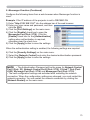
1.6.1 Profile connection
Selecting a profile data connect the network
with the projector.
It is required to store the profile data in
advance. (33)
1) Select the [Profile].
2) Choose a profile data listed in the window.
3) Click the [Connect].
4) The network connection will be established.
Proceed to item 1.8 Confirming the
connection to your destination. (30)
NOTE • To check the setting in a profile data, follow the process below.
1) Choose a profile data that you want to check.
2) Move the mouse cursor to the profile data, and click the right button on the
mouse to display a pop-up menu.
3) Select the “Property” in the pop-up menu, and click the left button on the
mouse.
4) The setting information of the selected profile data is shown.
• If the DHCP is set on in the projector, the network connection between the
projector and computer may not be established since IP address may be varied.
If you like to use the Profile connection, set the DHCP off in the projector.
23
1. Connection to the network
1.6 Manual configuration (continued)
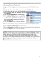
1.6.2 History connection
The “LiveViewer” can memory the network
settings when connecting to the projector as
a history record. After that, selecting a history
record can quickly connect the network with the
projector.
1) Select the [History].
2) Choose a history record listed in the window.
3) Click the [Connect].
4) The network connection will be established.
Proceed to item 1.8 Confirming the connection to your destination. (30)
If you want to copy a history record to a profile data, select one of the history
record and click the [Register to profile]. The profile data cannot be erased
automatically.
NOTE • The number of the history record is maximum 10 for each network
adapter. When the 11th data is stored, the oldest record among the 10 will be
overwritten.
• The date & time information in each history record is renewed when the
network is connected by using the history record.
• If the DHCP is set on in the projector, the network connection between the
projector and computer may not be established since IP address may be
varied.
• Even if you use the profile connection, it will be memorized as a history
record.
24
1. Connection to the network
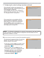
1.7 Configuring the network settings manually
All setting for the network connection between
the projector and computer is input manually.
Select the [Configure Network Settings
Manually].
The information to be input manually is different, depending on how you want to
connect the projector and computer.
Wireless LAN
The projector is required to be connected to an access point by a LAN cable. Go
to (26).
Wired LAN
If you use the wired LAN, go to (27).
25
1. Connection to the network
1.7 Configuring the network settings manually (continued)
Wireless LAN
1) The setting on the access point. *1
Enter the following information.
SSID: WirelessAccessPoint (example)
Encryption: WEP64bit (example)
Encryption key *2: ********** (example)
Mode: INFRASTRUCTURE
2) Click the [Next].
3) Enter the following information that is set in
the projector. *3
IP address : 192.168.1.10 (example)
Subnet mask: 255.255.255.0 (example)
4) Click the [Connect].
5) The wireless connection will be established.
Proceed to item 1.8 Confirming the connection to your destination. (30)
*1 Contact the network administrator to find out the setting on the access point.
*2 If you use an encryption, you need to set it. Contact the network administrator
to check the encryption key that is set in the projector.
The encryption key is always shown as “**********”.
*3 To find the network setting on the projector, refer to the NOTE. (22)
26
1. Connection to the network
1.7 Configuring the network settings manually (continued)
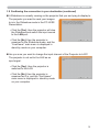
Wired LAN
1) Enter the following information for the
projector. *1
IP address : 192.168.1.10 (example)
Subnet mask : 255.255.255.0 (example)
2) Click the [Connect].
3) The network connection will be established.
Proceed to item 1.8 Confirming the connection to your destination. (30)
*1 To find the network setting on the projector, refer to the NOTE. (22)
[Troubleshooting]
A network connection could not be established.
Windows prevented network configuration
changes.
You may log in the Windows under User
authority.
Click the [OK], then the “LiveViewer” main
menu is displayed even though the network
is not established. Click
on the main
menu and go back to item 1.5 Selecting the
network connection method. (14)
Consult to the network administrator. Log in the Windows under Administrator
authority. After that, please resume at item 1.3.2 Starting the “LiveViewer”.
(9)
27
1. Connection to the network
1.7 Configuring the network settings manually (continued)
If you need to add a Network configuration on your computer to connect to the
projector.
This dialog will be displayed when you
need to add a Network configuration on
your computer to connect to the projector.
Confirm with your network administrator if
the Network configuration displayed on the
dialog is OK, and then click the [Yes].
Click the [NO], then the “LiveViewer” main menu is displayed even though the
network is not established. Click
on the main menu and go back to item 1.5
Selecting the network connection method. (14)
If you put a check mark in the box “Not displaying confirmation dialog for adding
Network settings”, the projector memorizes current configuration and this dialog
is not displayed again. To display this dialog again, click Option
icon in the
“LiveViewer” main menu and remove the check mark in the box “Not displaying
confirmation dialog for adding Network settings”.
If you want to change the Network
configuration to add, click the [Change]. A
dialog for changing the Network configuration
as shown to the right will be displayed. Enter
IP address and subnet mask , then click the
[OK]. Procedure to connect to the projector
will start.
Proceed to item 1.8 Confirming the
connection to your destination. (30)
If you click the [Cancel], you will return to the
dialog for adding a Network configuration.
28
1. Connection to the network
1.7 Configuring the network settings manually (continued)
If the entered IP address and projector's IP
address are the same, a warning dialog shown
to the right will be displayed.
Click the [OK], and then enter a different IP
address from the projector's one in the dialog
for changing Network configuration.
If the connection is not available with the
entered Network configuration, a warning
dialog shown to the right will be displayed.
Click the [OK] to return to the dialog for
changing the Network configuration, and then
enter appropriate configuration.
NOTE • If a Network configuration to connect to the projector has been added
on the computer, the added Network configuration will be erased once the
application software is closed.
Are you sure you want to connect the selected projector?
The message is appeared when the wireless
adapter you selected is already used for
another network connection.
• To connect, click the [Yes]. Proceed to item
1.8 Confirming the connection to your
destination. (30)
• Not to connect, click the [No] then the
“LiveViewer” main menu is displayed even
though the network is not established.
Click
on the main menu to go back
to item 1.5 Selecting the network
connection method. (14)
29
1. Connection to the network
1.8 Confirming the connection to your destination
1.8.1 Connection and transmission
When the network connection is established,
the “Connection to Projector successful” screen
is displayed.
Make sure that the right projector that you want
to send your image to is selected, by checking
the projector name and IP address shown in
the screen.
• To send images to the projector, click the [Yes]. The transmission will be started.
To display the transmitted images, select the LAN port as input source on the
projector.
• Not to send, click the [No], then the “LiveViewer” main menu is displayed
in stand-by mode. (Stand-by mode is the state where there is no image
transmission, although the network connection is established.)
The transmission can be started, if you click
or
button on the “LiveViewer”
main menu.
If you wish to use the current connection setting as a profile data for My
Connection, check in the box for the [Register this setting to My Connection].
[Troubleshooting]
This projector is currently in use (Presenting) by another user.
The projector you want to send your images
to is occupied by another computer in the
Presenter mode.
Click the [OK], then the “LiveViewer” main
menu is displayed in stand-by mode. Retry
to send your images, after the Presenter
mode is off.
30
1. Connection to the network
1.8 Confirming the connection to your destination (continued)
A Slideshow is currently running on the projector that you are trying to display to.
The projector you want to send your images
to is in the Slideshow mode in the PC-LESS
Presentation.
• Click the [Yes], then the projector will stop
the Slideshow and switch the input source
to the LAN port.
• Click the [No], then the projector is
remained in the Slideshow mode, and the
“LiveViewer” main menu is displayed in
stand-by mode on your computer.
Are you sure you want to change the input channel of the Projector to LAN?
The projector is not set to the LAN as an
input signal.
• Click the [Yes], then the projector is
switched to the LAN.
• Click the [No], then the projector is
remained as it is, and the “LiveViewer”
main menu is displayed in stand-by mode
on your computer.
31
1. Connection to the network
1.8 Confirming the connection to your destination (continued)
1.8.2 Connection error
When the connection to the projector could not
be established, an error message, “Network
Connection not established”, will come up.
Click the [OK] then the “LiveViewer” main
menu is displayed even though the network
is not established. Click
on the main menu
to go back to item 1.5 Selecting the network
connection method. (14)
NOTE • If My Connection is selected and the connection could not be
established, the “LiveViewer” main menu will not be displayed. Check the
network setting in the projector, and retry the connection from item 1.3.2
Staring the “LiveViewer”. (9)
32
1. Connection to the network
1.9 Profile data
1.9.1 Outline of Profile data
The network setting to connect the projector and computer can be stored as a
profile data. Once the data is stored, all you need to do is to select the data to
connect to the network. It is recommended when the same network connection is
often used.
1.9.2 Making Profile data
The profile data is made on the Manual
Configuration screen. (23)
Up to 10 profile data can be stored for each
network adapter.
1) Select the [Profile] and click the [New].
2) The “Create new profile” will come up.
If you have already made 10 profile data,
you cannot make a new one, until you delete
a stored data.
Input all information required for your
network connection.
If you want to clear the information you input,
click the [Clear].
3) Click the [OK], after all information is set.
If you don’t want to store it, click the [Cancel].
4) The new profile data is shown in the profile list, if you click the [OK].
NOTE • When you make a new profile data, it is strongly recommended to
check that the new dada can work properly by selecting the data at the Profile
connection. (23)
• If you change a network adapter on your computer, make a new profile data
for the adapter.
33
1. Connection to the network
1.9 Profile data (continued)
1.9.3 Editing Profile data
If necessary, the profile data can be edited on
the Manual Configuration screen. (23)
1) Select the [Profile], and select one of the
data listed in the window.
2) Click the [Edit].
3) The “Edit profile” screen will come up.
4) Edit the information required to be revised.
If you want to clear all information in the
window, click the [Clear].
5) Click the [OK], after the editing is completed.
If you don’t want to store it, click the [Cancel].
6) The edited profile data is stored and shown
in the profile list with the new date created
information, if you click the [OK].
NOTE • When you edit a profile data, it is strongly recommended to check
that the edited data can work properly by selecting the data at the Profile
connection. (23)
34
1. Connection to the network
1.9 Profile data (continued)
1.9.4 Registering My Connection
One of the profile data, which is often used, can be registered as the My
Connection profile data. Once the data is registered, all you need to do is to select
the My Connection to connect to the network. (12)
1) Click the [My Connection].
2) The “Add My Connection” screen will come
up.
The currently selected profile data for the My
Connection is shown with a check mark in
the list.
3) Select one of the profile data listed in the
window and put a mark in the check box.
The data selected before is turned
unmarked.
4) Click the [OK], then the window is closed.
If you don’t want to select a new one, click
the [Cancel].
NOTE • If you don’t want to use the My Connection, mark no data listed in the
window, and click the [OK].
• In the list, all profile data are shown no matter which network adapter is
selected. You can register a profile data that is not for currently selected
network adapter as the My Connection profile data.
35
1. Connection to the network
1.9 Profile data (continued)
Also, you can register a profile data to My
Connection, when the network connection
is established. When it is established, the
“Connection to Projector successful” screen is
displayed. (30)
If you wish to use the current connection
setting for My Connection, check in the box for
the [Register this setting to My Connection].
And then, if it is okay to overwrite the present
data for My Connection, click the [OK].
A new profile data will be created and it is
registered as My Connection profile data.
NOTE • If there are already 10 profile data, the check box cannot be checked.
Please erase one of the existing profile data.
• The profile name for the stored data is assigned by the “LiveViewer”
automatically. The name will be shown at the right side of the check box.
36
2. Network Presentation
2. Network Presentation
2.1 Using the “LiveViewer”
When you get the connection between your projector and computer, the
“LiveViewer” main menu will be shown on the computer screen.
On the main menu you can configure settings and operate functions to send your
images to the projector.
2.1.1 Main menu and Operating buttons
1) Menu Type
There are 2 type of the main menu, Easy type and Advanced type, which can
be switched on screen.
• When the “LiveViewer” is started, the last used type will be on screen.
• When the network connection is not established, the Advanced type will be on
screen.
Easy Type
Advanced Type
s
q
e
Switch to Advanced type
a
Status Display
r
w
Switch to
Easy type
Indicator
t
y
u
i
o
2) Operating buttons
q Starting Capture button
The transmission to the projector is started and the images will be displayed.
The Display mode will be the Single PC mode at first. After that, the last
Display mode will be applied.
w Stop button
The image transmission is stopped.
NOTE • The images may not be displayed on screen, if the Start/Stop buttons
are clicked repeatedly.
• The primary image is displayed in multi-display environment.
37
2. Network Presentation
2.1 Using the “LiveViewer” (continued)
e Hold button
The image on screen is temporally frozen.
The last image before the button is clicked is remained on screen.
You can revise the image data on your computer without showing it on the
projector’s screen.
r Display mode button (40)
The button switches the Single PC mode and Multi PC mode.
t Connect button
The screen to select the connection mode is displayed.
Go to item 1.5. (14)
y Option button
The option screen is displayed.
u Web control button
Starts the Web browser on your computer and displays Web control screen
to control the projector and change various settings for the projector. (45)
i Information button
The version of the “LiveViewer” is displayed.
o, a Close button
The network is disconnected and the “LiveViewer” is closed.
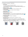
s Minimize button
The main menu is closed, and the “LiveViewer” icon is displayed on the
task tray in your computer. The displayed icon changes as shown below
depending on the status of the “LiveViewer”. If the icon is double-clicked, the
last type of the main menu will be shown on screen.
Connected
38
Disconnected
Not connected
Hold
2. Network Presentation
2.1 Using the “LiveViewer” (continued)
2.1.2 Displaying the status
1) Indicator
The indicator shows the following status.
Indicator
Status
Note
Not connected
The network connection to the projector is
not established yet.
Hold
The network connection is established, but
the image transmissions on hold.
Connected
The network connection is established and
the images on the computer are being sent
to the projector.
Disconnected
The network connection to the projector is
disconnected.
2) Status Display in Multi PC mode
The icon is displayed at the right end of the Display mode buttons.
One of the following icons to inform which quarter screens are used will be
shown.
Status
Status icon
No computer is on screen
One computer is on screen.
Two computers are on screen.
Three computers are on screen.
Four computers are on screen.
NOTE • The status display is refreshed in every 3 seconds.
• If the status cannot be gotten from the projector, it will not be displayed.
39
2. Network Presentation
2.1 Using the “LiveViewer” (continued)
2.1.3 Switching the display mode
The “LiveViewer” has the Single PC mode and Multi PC mode. The modes can be
switched on the main menu.
1) Click the
button on the main menu.
The buttons below are displayed.
q
w
e
r
t
y
y:Status Display
2) Select from q to t buttons, and click it.
q Switching to the Single PC mode : Your image is displayed on full screen.
w-t Switching to the Multi PC mode : Your image is displayed on a quarter
screen identified in the button.
3) The projector screen is switched to the mode selected above, and the
transmission of your computer image will be started to display your image on
the screen.
4) The icon
on the main menu is replaced by the icon you selected.
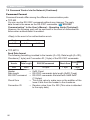
NOTE • The image transmission will be stopped, when you click the Single
mode button while the projector is in the Single PC mode or you click one of the
Multi mode buttons that shows the quarter screen which is currently displaying
your computer images in the Multi PC mode.
• If the Multi PC mode is selected, the projector screen is automatically divided
to 4 zones.
• If the Presenter mode is set on in the computer whose image is currently
on screen in the Single PC mode, the
button cannot be clicked on other
computers.
• If you select the button of the quarter screen displaying images from another
computer, the image transmission from that computer will be stopped.
The display mode can be set also by using the MULTI PC MODE in the
PRESENTATION item in the NETWORK menu. The last setting made will take
effect regardless of the setting method.
(Refer to NETWORK menu in the User’s Manual – Operating Guide for the
function on the projector.)
40
2. Network Presentation
2.1 Using the “LiveViewer” (continued)
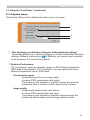
2.1.4 Option menu
Clicking the Option button displays the option menu on screen.
q
w
e
r
q “Not displaying confirmation dialog for adding Network settings”
This setting allows you to choose to display or not the confirmation dialog for
adding a Network configuration (19, 28) when you connect your computer
to the projector. It is turned off by default.
w Optimize Performance
The “LiveViewer” captures computer screen in JPEG data and sends the
JPEG data to the projector. The “LiveViewer” has two options that have
different compression rate of JPEG data.
Transmission speed
Speed takes priority over Image quality.
It makes JPEG compression rate higher.
The screen on the projector is rewritten quicker because the
transferred data is smaller, but the image quality is worse.
Image quality
Image quality takes priority over Speed.
It makes JPEG compression rate lower.
The screen on the projector is rewritten slower because the
transferred data is larger, but the image quality is better.
41
2. Network Presentation
2.1 Using the “LiveViewer” (continued)
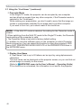
e Presenter Mode
In the Single PC mode, the projector can be occupied by one computer
and can block an access from any other computer, if the Presenter mode is
selected in the “LiveViewer”.
While making your presentation, you don’t need to worry that the image on
screen is unexpectedly switched to an image sent by another computer.
If you want to turn it on, put a check mark in the check box.
NOTE • If the Multi PC mode is selected, the setting for the Presenter mode is
invalid.
• When switching from the Multi PC mode to the Single PC mode, the Presenter
mode setting of the computer is valid.
• The Presenter Mode is set valid in factory default setting.
• In addition to using the software menu on the computer on which Presenter
Mode is turned on, you can cancel this function by using the projector's OSD
menu QUIT PRESENTER MODE EXECUTE of the PRESENTATION item in
the NETWORK menu.
r Display User Name
A “User Name” that is up to 20 letters can be input by using alphanumeric
characters.
The user name can be displayed on the projector screen, so you can find out
whose image is currently on the screen.
(Refer to NETWORK menu in the User’s Manual – Operating Guide)
If the check box is not marked, the information is not sent to the projector.
42
2. Network Presentation
2.2 Starting the Network Presentation
This chapter explains the Network Presentation feature with which you can project
computer images transmitted through a network.
The “LiveViewer” allows you to project images from one or multiple computers by
connecting the projector to an existing network without using computer cables.
This Network Presentation feature helps you to smoothly make your presentations
and conduct conferences.
To start the Network Presentation, select the LAN port as the input source on the
projector and click the Starting Capture button on the “LiveViewer”.
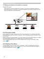
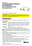
2.2.1 Display mode
Two display modes, Single PC mode and Multi PC mode, are available for the
Network Presentation.
1) Single PC mode
The projector displays images sent by one computer.
43
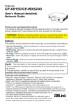
2. Network Presentation
2.2 Starting the Network Presentation (continued)
2) Multi PC mode
The projector screen is divided to 4 zones. The projector displays images in
one zone sent by a computer, so that the projector can display images sent by
up to 4 computers at the same time.
1
2
3
4
2.2.2 Presenter mode
In the Single PC mode, the projector can be occupied by one computer and can
block an access from any other computer, if the Presenter mode is selected in the
“LiveViewer”.
While making your presentation, you don’t need to worry that the image on screen
is unexpectedly switched to an image sent by another computer.
The Presenter mode can be set on the Option menu in the “LiveViewer” main
menu. (41)
2.2.3 Display User Name
A “User Name” can be input in the “LiveViewer”, which is displayed on screen
by operating the menu on the projector. So, it can be found out whose image is
currently displayed on screen. (41)
44
3. Web Control
3. Web Control
You can adjust or control the projector via a network from a web browser on a
computer that is connected to the same network.
NOTE • Internet Explorer 6.0 or later is required.
• If JavaScript is disabled in your web browser configuration, you must enable
JavaScript in order to use the projector web pages properly. See the Help files
for your web browser for details on how to enable JavaScript.
• It is recommended that all web browser updates are installed.
45
3. Web Control
3.1 Logon
To use the Web Control function, you need to logon with your user name and
password. (47)
Refer to the following for configuring or controlling the projector via a web browser.
Example: If the IP address of the projector is set to 192.168.1.10:
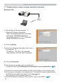
1) Display the logon window as shown on the right.
There are two options to display this window.
q Using the “LiveViewer”
Connect your computer and the projector
via Network using the “LiveViewer”. (9)
Then click the Web Control button
on
the “LiveViewer” main menu (37) to
start the Web browser software.
w Using Web browser software
Make sure that your computer and the
projector is connected via network, and
then start Web browser.
Enter the projector's IP address into URL
input box of the Web browser as the example below, and then press the
Enter key or
button.
Example: If the IP address of the projector is set to 192.168.1.10:
Enter “http://192.168.1.10/” into the address bar of the web
browser and press the Enter key or click
button.
2) Enter your user name and password, and then click the [OK].
NOTE • The language used on the Web Control screen is the same as that
of the OSD on the projector. If you want to change it, you need to change the
OSD language on the projector. (SCREEN menu in the User’s Manual –
Operating Guide)
46
3. Web Control
3.1 Logon (Continued)
Below are the factory default settings for user name and password.
User name
Password
Administrator
<blank>
If you logon successfully, the screen below will be displayed.
Main menu
3) Click the desired operation or configuration item on the main menu.
47
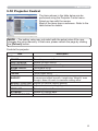
3. Web Control
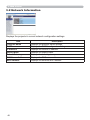
3.2 Network Information
Displays the projector’s current network configuration settings.
Item
Description
Projector Name
Displays the projector name settings.
DHCP
Displays the DHCP configuration settings.
IP Address
Displays the current IP address.
Subnet Mask
Displays the subnet mask.
Default Gateway
Displays the default gateway.
DNS Server Address
Displays the DNS server address.
MAC Address
Displays the ethernet MAC address.
48
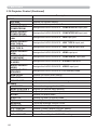
3. Web Control
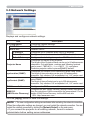
3.3 Network Settings
Displays and configures network settings.
Item
IP Configuration
Description
Configures network settings.
DHCP ON
Enables DHCP.
DHCP OFF
Disables DHCP.
IP Address
Configures the IP address when DHCP is disabled.
Subnet Mask
Configures the subnet mask when DHCP is disabled.
Default Gateway
Configures the default gateway when DHCP is disabled.
Projector Name
Configures the name of the projector.
The length of the Projector Name can be up to 64 alphanumeric
characters. Only alphabets, numbers and following symbols
can be used. !"#$%&'()*+,-./:;<=>?@[\]^_`{|}~ and space.
Particular projector name is pre-assigned by default.
sysLocation (SNMP)
Configures the location to be referred to when using SNMP.
The length of the sysLocation can be up to 255 alphanumeric
characters. Only numbers ‘0-9’ and alphabet ‘a-z’, ‘A-Z’ can be used.
sysContact (SNMP)
Configures the contact information to be referred to when
using SNMP.
The length of the sysContact can be up to 255 alphanumeric
characters. Only numbers ‘0-9’ and alphabet ‘a-z’, ‘A-Z’ can be used.
DNS Server Address
Configures the DNS server address.
AMX D.D.
(AMX Device Discovery)
Configures the AMX Device Discovery setting to detect the projector
from the controllers of AMX connected to the same network. For the
details of AMX Device Discovery, visit the AMX web site.
URL: http://www.amx.com
Click the [Apply] button to save the settings.
NOTE • The new configuration settings are activated after restarting the network connection.
When the configuration settings are changed, you must restart the network connection. You can
restart the network connection by clicking the [Network Restart] on the main menu.
• If you connect the projector to an existing network, consult a network
administrator before setting server addresses.
49
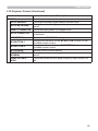
3. Web Control
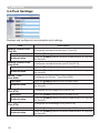
3.4 Port Settings
Displays and configures communication port settings.
Item
Network Control Port1
(Port:23)
Configures command control port 1 (Port:23).
Port open
Click the [Enable] check box to use port 23.
Authentication
Click the [Enable] check box when authentication is required
for this port.
Network Control Port2
(Port:9715)
Configures command control port 2 (Port:9715).
Port open
Click the [Enable] check box to use port 9715.
Authentication
Click the [Enable] check box when authentication is required
for this port.
PJLink TM Port
(Port:4352)
Configures the PJLink TM port (Port:4352).
Port open
Click the [Enable] check box to use port 4352.
Authentication
Click the [Enable] check box when authentication is required
for this port.
My Image Port
(Port:9716)
Configures the My Image Port (Port:9716).
Port open
Click the [Enable] check box to use port 9716.
Authentication
Click the [Enable] check box when authentication is required
for this port.
Messenger Port
(Port:9719)
50
Description
Configures the Messenger Port (Port:9719).
Port open
Click the [Enable] check box to use port 9719.
Authentication
Click the [Enable] check box when authentication is required
for this port.
3. Web Control
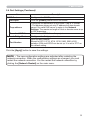
3.4 Port Settings (Continued)
Item
SNMP Port
Description
Configures the SNMP port.
Port open
Click the [Enable] check box to use SNMP.
Trap address
Configures the destination of the SNMP Trap in IP format.
• The address allows not only IP address but also domain
name if the valid DNS server is setup in the Network
Settings. The maximum length of host or domain name is up
to 255 characters.
Download MIB file
Downloads a MIB file from the projector.
Network Bridge Port
Port Number
Configures the Bridge port number.
Input the port number.
Except for 9715, 9716, 9719, 9720, 5900, 5500, 4352
between 1024 and 65535 can be set up. It is set to 9717 as
the default setting.
Click the [Apply] button to save the settings.
NOTE • The new configuration settings are activated after restarting the
network connection. When the configuration settings are changed, you must
restart the network connection. You can restart the network connection by
clicking the [Network Restart] on the main menu.
51
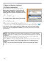
3. Web Control
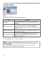
3.5 Mail Settings
Displays and configures e-mail addressing settings.
Item
Description
Send Mail
Click the [Enable] check box to use the e-mail function.
Configure the conditions for sending e-mail under the Alert
Settings.
SMTP Server Address
Configures the address of the mail server in IP format.
• The address allows not only IP address but also domain
name if the valid DNS server is setup in the Network
Settings. The maximum length of host or domain name is up
to 255 characters.
Sender E-mail address
Configures the sender e-mail address.
The length of the sender e-mail address can be up to 255
alphanumeric characters.
Configures the e-mail address of up to five recipients. You
can also specify the [TO] or [CC] for each address. The
Recipient E-mail address
length of the recipient e-mail address can be up to 255
alphanumeric characters.
Click the [Apply] button to save the settings.
NOTE • You can confirm whether the mail settings work correctly using the
[Send Test Mail] button. Please enable Send mail setting before clicking the
[Send Test Mail].
• If you connect the projector to an existing network, consult a network
administrator before setting server addresses.
52
3. Web Control
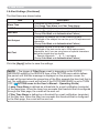
3.6 Alert Settings
Displays and configures failure & alert settings.
Item
Description
Cover Error
The lamp cover has not been properly fixed.
Fan Error
The cooling fan is not operating.
Lamp Error
The lamp does not light, and there is a possibility that interior
portion has become heated.
Temp Error
There is a possibility that the interior portion has become
heated.
Air Flow Error
The internal temperature is rising.
Cold Error
There is a possibility that the interior portion has become
overcooled.
Filter Error
Filter time over.
Other Error
Other error.
If displaying this error, please contact your dealer.
Schedule Execution
Error
Schedule Execution error. (55)
Lamp Time Alarm
Lamp time over Alarm Time setting.
Filter Time Alarm
Filter time over Alarm Time setting.
Transition Detector
Alarm
Transition Detector Alarm. (OPTION menu in the User’s
Manual – Operating Guide)
Cold Start
When the projector is supplied with the power, it works as
below.
• If the STANDBY MODE is set to the NORMAL:the projector's
power status changes from “OFF” to “Standby state”.
• If the STANDBY MODE is set to the SAVING:the projector's power
status changes from “Standby state” to “ON (lamp is turned on)”.
(SETUP menu in the User’s Manual – Operating Guide)
Authentication Failure
The SNMP access is detected from the invalid SNMP community.
Refer to “Troubleshooting” in the User’s Manual – Operating Guide for
further detailed explanation of Error except Other Error and Schedule Execution
Error.
53
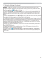
3. Web Control
3.6 Alert Settings (Continued)
The Alert Items are shown below.
Item
Description
Alarm Time
Configures the time to alert.
(Only Lamp Time Alarm and Filter Time Alarm.)
SNMP Trap
Click the [Enable] check box to enable SNMP Trap alerts.
Send Mail
Click the [Enable] check box to enable e-mail alerts.
(Except Cold Start and Authentication Failure.)
Mail Subject
Configures the subject line of the e-mail to be sent.
The length of the subject line can be up to 100 alphanumeric
characters.
(Except Cold Start and Authentication Failure.)
Mail Text
Configures the text of the e-mail to be sent.
The length of the text can be up to 1024 alphanumeric
characters, but if you are using some of special characters
below the length may be shorter.
Special characters " ' : & , % \ and space
(Except Cold Start and Authentication Failure.)
Click the [Apply] button to save the settings.
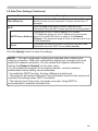
NOTE • The trigger of Filter Error e-mail is depending on the FILTER
MESSAGE setting in the SERVICE item of the OPTION menu which defines
the period until the filter message is displayed on the projector screen. An
e-mail will be sent when the usage time of the filter exceeds the time limit that is
set. No notification e-mail will be sent if the FILTER MESSAGE is set to TURN
OFF. (OPTION menu in the User’s Manual – Operating Guide)
• Lamp Time Alarm is defined as a threshold for e-mail notification (reminder)
of the lamp timer. When the lamp hour exceeds this threshold that is configured
through the Web page, the e-mail will be sent out.
• Filter Time Alarm is defined as a threshold for e-mail notification (reminder)
of the filter time. When the filter hour exceeds this threshold that is configured
in the Web page, the e-mail will be sent out.
54
3. Web Control
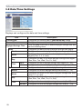
3.7 Schedule Settings
Displays and configures schedule settings.
Item
Description
Daily
Configures the daily schedule.
Sunday
Configures the Sunday schedule.
Monday
Configures the Monday schedule.
Tuesday
Configures the Tuesday schedule.
Wednesday
Configures the Wednesday schedule.
Thursday
Configures the Thursday schedule.
Friday
Configures the Friday schedule.
Saturday
Configures the Saturday schedule.
Specific date No.1
Configures the specific date (No.1) schedule.
Specific date No.2
Configures the specific date (No.2) schedule.
Specific date No.3
Configures the specific date (No.3) schedule.
Specific date No.4
Configures the specific date (No.4) schedule.
Specific date No.5
Configures the specific date (No.5) schedule.
55
3. Web Control
3.7 Schedule Settings (Continued)
The schedule settings are shown below.
Item
Description
Schedule
Click the [Enable] check box to enable the schedule.
Date (Month/Day)
Configures the month and date.
This item appears only when Specific date (No. 1-5) is
selected.
Click the [Apply] button to save the settings.
The current event settings are displayed on the schedule list. To add additional
functions and events, set the following items.
Item
Description
Time
Configures the time to execute commands.
Command
[Parameter]
Configures the commands to be executed.
Power
Configures the parameters for power control.
Input Source
Configures the parameters for input switching.
My Image
Configures the parameters for My Image data display. (70)
Messenger
Configures the parameters for Messenger data display. (72)
Slideshow
Configures the Start/Stop parameters for the Slideshow.
Click the [Register] button to add new commands to the schedule list.
Click the [Delete] button to delete commands from the schedule list.
Click the [Reset] button to delete all commands and reset the schedule settings
from the schedule list.
56
3. Web Control
3.7 Schedule Settings (Continued)
NOTE • After the projector is moved, check the date and time set for the
projector before configuring the schedules. Strong shock may make the date
and time settings (58) get out of tune.
• Events “My Image” and “Messenger” will not be executed appropriately but
result in “schedule execution error” status in case lamp does not light or/and
display data are not stored in the projector at the scheduled event execution
time.
• Events “Input Source” and “My Image” will not be executed if security feature
is enabled and the projector is locked due to the feature.
• Certain error state in the projector (such as temperature error, lamp error) will
prevent the projector from appropriate execution of scheduled functions/events.
• If no USB memory device is inserted to the projector or no image data for
display exists at the scheduled event time, a schedule execution error occurs
against the scheduled Slideshow event.
• When you start the Slideshow, input source will be automatically switched to
the USB TYPE A port.
• Image files stored in the root directory of the USB memory device will be
displayed for the scheduled Slideshow.
• Please refer to “Troubleshooting” in the User's Manual – Operating
Guide in case scheduled functions/events are not executed appropriately as
you've set.
57
3. Web Control
3.8 Date/Time Settings
Displays and configures the date and time settings.
Item
Description
Current Date
Configures the current date in year/month/day format.
Current Time
Configures the current time in hour:minute:second format.
Daylight Savings Time
Click the [ON] check box to enable daylight savings time and
set the following items.
Start
Configures the date and time daylight savings time begins.
Month
Configures the month daylight savings time begins (1~12).
Week
Configures the week of the month daylight savings time
begins (First, 2, 3, 4, Last).
Day
Configures the day of the week daylight savings time begins
(Sun, Mon, Tue, Wed, Thu, Fri, Sat).
Time
hour
Configures the hour daylight savings time begins (0 ~ 23).
minute
Configures the minute daylight savings time begins (0 ~ 59).
End
Month
Configures the month daylight savings time ends (1 ~ 12).
Week
Configures the week of the month daylight savings time ends
(First, 2, 3, 4, Last).
Day
Configures the day of the week daylight savings time ends
(Sun, Mon, Tue, Wed, Thu, Fri, Sat).
Time
58
Configures the date and time daylight savings time ends.
hour
Configures the hour daylight savings time ends (0 ~ 23).
minute
Configures the minute daylight savings time ends (0 ~ 59).
3. Web Control
3.8 Date/Time Settings (Continued)
Item
Description
Time difference
Configures the time difference. Set the same time difference
as the one set on your computer. If unsure, consult your IT
manager.
SNTP
Click the [ON] check box to retrieve Date and Time
information from the SNTP server and set the following items.
Configures the SNTP server address in IP format.
• The address allows not only IP address but also domain
SNTP Server Address name if the valid DNS server is setup in the Network
Settings. The maximum length of host or domain name is up
to 255 characters.
Cycle
Configures the interval at which to retrieve Date and Time
information from the SNTP server (hour:minute).
Click the [Apply] button to save the settings.
NOTE • The new configuration settings are activated after restarting the
network connection. When the configuration settings are changed, you must
restart the network connection. You can restart the network connection by
clicking the [Network Restart] on the main menu.
• If you connect the projector to an existing network, consult a network
administrator before setting server addresses.
• To enable the SNTP function, the time difference must be set.
• The projector will retrieve Date and Time information from the time server and
override time settings when SNTP is enabled.
• The internal clock’s time may not remain accurate. Using SNTP is
recommended to maintain accurate time.
59
3. Web Control
3.9 Security Settings
Displays and configures passwords and other security settings.
Item
User Account
Description
Configures the user name and password.
User name
Configures the user name.
The length of the text can be up to 32 alphanumeric
characters.
Password
Configures the password.
The length of the text can be up to 255 alphanumeric
characters.
Re-enter Password
Reenter the above password for verification.
Network Control
Configures the Authentication password for the command
control.
Authentication
Password
Configures the Authentication password. The length of the
text can be up to 32 alphanumeric characters.
Re-enter
Authentication
Password
Reenter the above password for verification.
SNMP
Community name
Configures the community name if SNMP is used.
Configures the community name. The length of the text can
be up to 64 alphanumeric characters.
Click the [Apply] button to save the settings.
NOTE • The new configuration settings are activated after restarting the
network connection. When the configuration settings are changed, you must
restart the network connection. You can restart the network connection by
clicking the [Network Restart] on the main menu.
• Only numbers ‘0-9’ and alphabet ‘a-z’, ‘A-Z’ can be used.
60
3. Web Control
3.10 Projector Control
The items shown in the table below can be
performed using the Projector Control menu.
Select an item with the mouse.
Most of the items have a submenu. Refer to the
table below for details.
NOTE • The setting value may not match with the actual value if the user
changes the value manually. In that case, please refresh the page by clicking
the [Refresh] button.
Controls the projector.
Item
Description
MAIN
POWER
INPUT SOURCE
PICTURE MODE
BLANK ON/OFF
MUTE
FREEZE
Turns the power on/off.
Selects the input source.
Selects the picture mode setting.
Turns Blank on/off.
Turns Mute on/off.
Turns Freeze on/off.
Controls the magnify setting.
MAGNIFY
In some input signal sources, it might stop “Magnify” even
though it does not reach to maximum setting value.
MAGNIFY POSITION V Adjusts the vertical magnify position.
MAGNIFY POSITION H Adjusts the horizontal magnify position.
TEMPLATE
Turns template on/off.
MY IMAGE
Selects MY IMAGE data.
MY IMAGE DELETE
Deletes MY IMAGE data.
61
3. Web Control
3.10 Projector Control (Continued)
Item
PICTURE
BRIGHTNESS
CONTRAST
GAMMA
COLOR TEMP
COLOR
TINT
SHARPNESS
ACTIVE IRIS
MYMEMORY SAVE
MYMEMORY RECALL
IMAGE
ASPECT
OVER SCAN
V POSITION
H POSITION
H PHASE
H SIZE
AUTO ADJUST
EXECUTE
INPUT
PROGRESSIVE
VIDEO NR
COLOR SPACE
COMPONENT
S-VIDEO FORMAT
C-VIDEO FORMAT
HDMI FORMAT
HDMI RANGE
COMPUTER IN1
COMPUTER IN2
FRAME LOCK COMPUTER IN1
FRAME LOCK COMPUTER IN2
FRAME LOCK - HDMI
62
Description
Adjusts the brightness setting.
Adjusts the contrast setting.
Selects the gamma setting.
Selects the color temperature setting.
Adjusts the color setting.
Adjusts the tint setting.
Adjusts the sharpness setting.
Selects the active iris setting.
Saves the MyMemory data.
Recalls the MyMemory data.
Selects the aspect setting.
Adjusts the over scan setting.
Adjusts the vertical position.
Adjusts the horizontal position.
Adjusts the horizontal phase.
Adjusts the horizontal size.
Performs the automatic adjustment.
Selects the progressive setting.
Selects the video noise reduction setting.
Selects the color space.
Selects the COMPONENT port setting.
Selects the s-video format setting.
Selects the video format setting.
Selects the HDMI format setting.
Selects the HDMI range setting.
Selects the COMPUTER IN1 input signal type.
Selects the COMPUTER IN2 input signal type.
Turns the FRAME LOCK-COMPUTER IN1 function on/off.
Turns the FRAME LOCK-COMPUTER IN2 function on/off.
Turns the FRAME LOCK-HDMI function on/off.
3. Web Control
3.10 Projector Control (Continued)
Item
SETUP
AUTO KEYSTONE
EXECUTE
KEYSTONE V
KEYSTONE H
Description
Performs the automatic keystone distortion setting.
Adjusts the vertical keystone distortion setting.
Adjusts the horizontal keystone distortion setting.
Adjusts the shape of the projected image in each of the
PERFECT FIT
corners and sides.
AUTO ECO MODE
Turns on/off the automatic eco mode function.
ECO MODE
Selects the eco mode.
MIRROR
Selects the mirror status.
STANDBY MODE
Selects the standby mode.
Assigns the MONITOR OUT when the COMPUTER IN1 input
MONITOR OUT COMPUTER IN1
port is selected.
MONITOR OUT Assigns the MONITOR OUT when the COMPUTER IN2 input
COMPUTER IN2
port is selected.
Assigns the MONITOR OUT when the LAN input port is
MONITOR OUT - LAN
selected.
MONITOR OUT - USB Assigns the MONITOR OUT when the USB TYPE A input
TYPE A
port is selected.
MONITOR OUT - USB Assigns the MONITOR OUT when the USB TYPE B input
TYPE B
port is selected.
MONITOR OUT Assigns the MONITOR OUT when the HDMI input port is
HDMI
selected.
MONITOR OUT Assigns the MONITOR OUT when the COMPONENT input
COMPONENT
port is selected.
MONITOR OUT Assigns the MONITOR OUT when the S-VIDEO input port is
S-VIDEO
selected.
MONITOR OUT Assigns the MONITOR OUT when the VIDEO input port is
VIDEO
selected.
MONITOR OUT Assigns the MONITOR OUT in the standby mode.
STANDBY
63
3. Web Control
3.10 Projector Control (Continued)
Item
AUDIO
VOLUME
SPEAKER
AUDIO SOURCE COMPUTER IN1
AUDIO SOURCE COMPUTER IN2
AUDIO SOURCE LAN
AUDIO SOURCE USB TYPE A
AUDIO SOURCE USB TYPE B
AUDIO SOURCE HDMI
AUDIO SOURCE COMPONENT
AUDIO SOURCE S-VIDEO
AUDIO SOURCE VIDEO
AUDIO SOURCE STANDBY
HDMI AUDIO
MIC LEVEL
MIC VOLUME
SCREEN
LANGUAGE
MENU POSITION V
MENU POSITION H
BLANK
START UP
MyScreen Lock
MESSAGE
TEMPLATE
C.C. - DISPLAY
C.C. - MODE
C.C. - CHANNEL
64
Description
Adjusts the volume setting.
Turns the built-in speaker on/off.
Assigns the AUDIO SOURCE - COMPUTER IN1 input port.
Assigns the AUDIO SOURCE - COMPUTER IN2 input port.
Assigns the AUDIO SOURCE - LAN input port.
Assigns the AUDIO SOURCE - USB TYPE A input port.
Assigns the AUDIO SOURCE - USB TYPE B input port.
Assigns the AUDIO SOURCE - HDMI input port.
Assigns the AUDIO SOURCE - COMPONENT input port.
Assigns the AUDIO SOURCE - S-VIDEO input port.
Assigns the AUDIO SOURCE - VIDEO input port.
Assigns the AUDIO SOURCE in the standby mode.
Selects the HDMI audio setting.
Selects the microphone level.
Adjusts the microphone volume setting.
Selects the language for the OSD.
Adjusts the vertical Menu position.
Adjusts the horizontal Menu position.
Selects the Blank mode.
Selects the start up screen mode.
Turns MyScreen lock function on/off.
Turns the message function on/off.
Selects the template setting.
Selects Closed Caption DISPLAY setting.
Selects Closed Caption MODE setting.
Selects Closed Caption CHANNEL setting.
3. Web Control
3.10 Projector Control (Continued)
Item
OPTION
AUTO SEARCH
AUTO KEYSTONE
DIRECT POWER ON
AUTO POWER OFF
USB TYPE B
MY BUTTON-1
MY BUTTON-2
MY SOURCE
REMOTE FREQ. NORMAL
REMOTE FREQ. HIGH
Description
Turns the automatic signal search function on/off.
Turns the automatic keystone distortion correction function
on/off.
Turns the direct power on function on/off.
Configures the timer to shut off the projector when no signal
is detected.
Selects the USB TYPE B setting.
Assigns the functions for the MY BUTTON-1 button on the
included remote control.
Assigns the functions for the MY BUTTON-2 button on the
included remote control.
Selects the My Source setting.
Turns the remote control signal frequency normal function
on/off.
Turns the remote control signal frequency high function on/
off.
65
3. Web Control
3.10 Projector Control (Continued)
The items shown in the table below can be
performed using the Projector Control menu.
Click the [QUIT PRESENTER MODE].
Item
Description
SERVICE
QUIT PRESENTER
MODE
66
Quit compulsorily from the Presenter mode.
3. Web Control
3.11 Remote Control
You can use your Web browser to control the
projector.
• Do not attempt to control the projector with
the projector’s remote control and via your Web
browser at the same time. It may cause some
operational errors in the projector.
The functions on the bundled remote control are assigned to the Web Remote
Control screen.
Item
Description
POWER
Assigned the same operation as STANDBY/ON button.
COMPUTER
Assigned the same operation as COMPUTER button.
VIDEO
Assigned the same operation as VIDEO button.
BLANK
Assigned the same operation as BLANK button.
FREEZE
Assigned the same operation as FREEZE button.
MUTE
Assigned the same operation as MUTE button.
MENU
Assigned the same operation as MENU button.
▲
Assigned the same operation as ▲ button.
▼
Assigned the same operation as ▼ button.
◄
Assigned the same operation as ◄ button.
►
Assigned the same operation as ► button.
ENTER
Assigned the same operation as ENTER button.
RESET
Assigned the same operation as RESET button.
PAGE UP
Assigned the same operation as PAGE UP button.
PAGE DOWN
Assigned the same operation as PAGE DOWN button.
SLIDESHOW
Starts the Slideshow.
NOTE • The Web Remote Control does not support repeat function that
performs an action while holding a button clicked down.
• Since the repeat function is not available, click the button repeatedly as many
times as you require.
• Even if you hold the button clicked down for a while, the Web Remote Control
sends your request command one time only. Release the button, then click it again.
• When the [POWER] button is pushed, a message window comes up to confirm
the operation. To control the power, push [OK], otherwise push [Cancel].
• The [PAGE DOWN] and [PAGE UP] buttons on the Web Remote Control
cannot be used as mouse emulation function of the projector.
67
3. Web Control
3.12 Projector Status
Displays and configures the current projector status.
Item
Description
Error Status
Displays the current error status
Lamp Time
Displays the usage time for the current lamp.
Filter Time
Displays the usage time for the current filter.
Power Status
Displays the current power status.
Input Status
Displays the current input signal source.
Blank On/Off
Displays the current Blank on/off status.
Mute
Displays the current Mute on/off status.
Freeze
Displays the current Freeze status.
68
3. Web Control
3.13 Network Restart
Restarts the projector’s network connection.
Item
Restart
Description
Restarts the projector’s network connection in order to
activate new configuration settings.
NOTE • Restarting requires you to re-log on in order to further control or
configure the projector via a web browser. Wait 30 seconds or more after
clicking the [Restart] button to log on again.
69
4. My Image Function
4. My Image Function
The projector can display still images that are transferred via the network.
Transfer image data
Display image data ( 1 -
4
)
MY IMAGE transmission requires an exclusive application for your computer.
“PJImg/Projector Image Tool” is necessary to use MY IMAGE transmission.
It can be downloaded from the Hitachi web site (http://www.hitachi-america.us/
digitalmedia or http://www.hitachidigitalmedia.com).
Refer to the manual for the application for instructions.
To display the transferred image, select the MY IMAGE item in the NETWORK
menu. For more information, please see the description of the MY IMAGE item of
the NETWORK menu. (NETWORK menu in User’s Manual – Operating Guide)
NOTE • It is possible to allocate the image file up to 4 in the maximum.
• Using MY BUTTON that registered MY IMAGE can display transferred image.
(OPTION menu in the User’s Manual – Operating Guide)
• The image file also can be displayed by using schedule function from the web
browser. Refer to item 7.3 Event Scheduling (81) in detail.
• If you display MY IMAGE data on screen while you are using the USB Display
function, the application for the USB Display will be closed. To restart the
application, exit the MY IMAGE function, and then the software in the projector,
LiveViewerLiteUSB.exe, will run again. (USB Display in the User’s Manual
– Operating Guide)
70
4. My Image Function
4. My Image Function (Continued)
Configure the following items from a web browser when MY IMAGE function is
used.
Example: If the IP address of the projector is set to 192.168.1.10:
1) Enter "http://192.168.1.10/" into the address bar of the web browser.
2) Enter your user name and password, and then
click the [OK].
3) Click the [Port Settings] on the main menu.
4) Click the [Enable] check box to open the My
Image Port (Port: 9716). Click the [Enable]
check box for the [Authentication] setting
when authentication is required, otherwise
clear the check box.
5) Click the [Apply] button to save the settings.
When the authentication setting is enabled, the following settings are required.
6) Click the [Security Settings] on the main menu.
7) Select the [Network Control] and enter the desired authentication password.
8) Click the [Apply] button to save the settings.
NOTE • The Authentication Password will be the same for Network Control
Port1 (Port: 23), Network Control Port2 (Port: 9715), PJLink™ Port (Port:
4352), My Image Port (Port: 9716) and Messenger Port (Port: 9719).
• The new configuration settings are activated after restarting the network
connection. When the configuration settings are changed, you must restart the
network connection. You can restart the network connection by clicking the
[Network Restart] on the main menu.
71
5. Messenger Function
5. Messenger Function
The projector can display the text data transferred via the network on the screen.
The text data can be displayed on the screen in two ways that displays the text
transferred from the computer on real time, and the other chooses and displays
the text data from the ones once stored in the projector.
Transfer text data
1
2
3
4
Display text data (ex.
4
)
Messenger function requires an exclusive application for your computer. To edit,
transfer and display the text data, use the application. You can download it from
the Hitachi web site (http://www.hitachi-america.us/digitalmedia or http://www.
hitachidigitalmedia.com). Refer to the manual for the application for the details of
Messenger function and instructions of the application.
NOTE • It is possible to store the text data up to 12 in the maximum.
• Using MY BUTTON that registered MESSENGER can turn the displaying
messenger text on/off. (OPTION menu in the User’s Manual – Operating
Guide)
• The text file also can be displayed by using schedule function via the web
browser. Refer to item 7.3 Event Scheduling (81) for the detail.
72
5. Messenger Function
5. Messenger Function (Continued)
Configure the following items from a web browser when Messenger function is
used.
Example: If the IP address of the projector is set to 192.168.1.10:
1) Enter "http://192.168.1.10/" into the address bar of the web browser.
2) Enter your user name and password, and then
click the [OK].
3) Click the [Port Settings] on the main menu.
4) Click the [Enable] check box to open the
Messenger Port (Port: 9719). Click the
[Enable] check box for the [Authentication]
setting when authentication is required,
otherwise clear the check box.
5) Click the [Apply] button to save the settings.
When the authentication setting is enabled, the following settings are required.
6) Click the [Security Settings] on the main menu.
7) Select the [Network Control] and enter the desired authentication password.
8) Click the [Apply] button to save the settings.
NOTE • The Authentication Password will be the same for Network Control
Port1 (Port: 23), Network Control Port2 (Port: 9715), PJLink™ Port (Port:
4352), My Image Port (Port: 9716) and Messenger Port (Port: 9719).
• The new configuration settings are activated after restarting the network
connection. When the configuration settings are changed, you must restart the
network connection. You can restart the network connection by clicking the
[Network Restart] on the main menu.
73
6. Network Bridge Function
6. Network Bridge Function
This projector is equipped with the NETWORK BRIDGE function to perform
mutual conversion of a network protocol and a serial interface.
Using the NETWORK BRIDGE function, a computer that is connected with
this projector by Ethernet communication can control an external device that is
connected with this projector by RS-232C communication as a network terminal.
TCP/IP data
Protocol change
Ethernet
LAN cable
Computer
LAN port
Serial data
RS-232C
RS-232C cable
External device
CONTROL port
6.1 Connecting devices
1) Connect the projector’s LAN port and the computer’s LAN port with a LAN
cable, for Ethernet communication.
2) Connect the projector’s CONTROL port and the device’s RS-232C port with
an RS-232C cable, for RS-232C communication.
NOTE • Before connecting the devices, read the manuals for the devices to
ensure the connection.
For RS-232C connection, check the specifications of each port and use
the suitable cable. (“Connection to the ports” in the User’s Manual –
Operating Guide (Technical))
74
6. Network Bridge Function
6.2 Communication setup
To configure the setup of the communication using NETWORK BRIDGE for
the projector, use items in the COMMUNICATION menu. Open the menu of
the projector and select the OPTION - SERVICE - COMMUNICATION menu.
(OPTION menu – SERVICE – COMMUNICATION in the User’s Manual –
Operating Guide)
1) Using the COMMUNICATION TYPE menu, select the NETWORK BRIDGE
for the CONTROL port.
2) Using the SERIAL SETTINGS menu, select the proper baud rate and parity
for the CONTROL port, according to the specification of the RS-232C port of
the connected device.
Item
BAUD RATE
PARITY
Condition
4800bps/9600bps/19200bps/38400bps
NONE/ODD/EVEN
Data length
8 bit (fixed)
Start bit
1 bit (fixed)
Stop bit
1 bit (fixed)
3) Using the TRANSMISSION METHOD menu, set up the proper method for the
CONTROL port according to your use.
NOTE • The OFF is selected for the COMMUNICATION TYPE as the default
setting.
• Using the COMMUNICATION menu, set up the communication. Remember
that an unsuitable setup could cause malfunction of communication.
• When COMMUNICATION TYPE is set to NETWORK BRIDGE, the CONTROL
port doesn't accept RS-232C commands.
6.3 Communication port
For the NETWORK BRIDGE function, send the data from the computer to the
projector with using the Network Bridge Port that is configured in the “Port
Settings” of web browser. (50)
NOTE • Except for 9715, 9716, 9719, 9720, 5900, 5500, 4352 between 1024
and 65535 can be set up as the Network Bridge Port number. It is set to 9717
as the default setting.
75
6. Network Bridge Function
6.4 Transmission method
The transmission method can be selected from the menus, only when the
NETWORK BRIDGE is selected for the COMMUNICATION TYPE.
(OPTION menu – SERVICE – COMMUNICATION in the User’s Manual –
Operating Guide)
HALF-DUPLEX FULL-DUPLEX
6.4.1 HALF-DUPLEX
This method lets the projector make two way communication, but only one
direction, either transmitting or receiving data, is allowed at a time.
The method does not allow the projector to receive the data from the computer
while waiting for response data from an external device. After the projector
receives the response data from an external device or the response limit time is
past, the projector can receive the data from the computer.
That means that the projector controls transmitting and receiving the data to
synchronize the communication.
To use the HALF-DUPLEX method, set up the RESPONSE LIMIT TIME following
the instructions below.
TCP/IP data
Ethernet
LAN cable
Computer
Protocol change
Serial data
RS-232C
RS-232C cable
External device
Transmitting data
Transmitting data
Discarding data
Response data
Response limit
time
Response data
Transmitting data
Using the RESPONSE LIMIT TIME menu, set the waiting time for response data
from an external device. (OPTION menu – SERVICE – COMMUNICATION
in the User’s Manual – Operating Guide)
OFF 1s 2s 3s ( OFF)
76
6. Network Bridge Function
6.4 Transmission method (Continued)
NOTE • With using the HALF-DUPLEX method, the projector can send out
254 byte data as maximum at once.
• If it is not required to monitor the response data from an external device and
the RESPONSE LIMIT TIME is set to OFF, the projector can receive the data
from the computer and send it out to an external device continuously.
The OFF is selected as the default setting.
6.4.2 FULL-DUPLEX
This method lets the projector make two way communication, transmitting and
receiving data at the same time, without monitoring response data from an
external device.
With using this method, the computer and an external device will send the data
out of synchronization. If it is required to synchronize them, set the computer to
make the synchronization.
NOTE • In case that the computer controls to synchronize transmitting
and receiving the data, it may not be able to control an external device well
depending on the processing status of the projector.
77
7. Other Functions
7. Other Functions
7.1 E-mail Alerts
The projector can automatically send an alert message to the specified e-mail
addresses when the projector detects a certain condition that is requiring
maintenance or detected an error.
NOTE • Up to five e-mail addresses can be specified.
• The projector may be not able to send e-mail if the projector suddenly loses
power.
Mail Settings (52)
To use the projector’s e-mail alert function, please configure the following items
through a web browser.
Example: If the IP address of the projector is set to 192.168.1.10:
1) Enter “http://192.168.1.10/” into the address bar of the web browser.
2) Enter your user name and password, and then click the [OK].
3) Click the [Mail Settings] and configure each item. Refer to item 3.5 Mail
Settings (52) for further information.
4) Click the [Apply] button to save the settings.
NOTE • Click the [Send Test Mail] button in the [Mail Settings] to confirm
that the e-mail settings are correct. The following mail will be delivered to the
specified addresses.
Subject line :Test Mail
Text
:Send Test Mail
Date
Time
IP Address
MAC Address
78
<Projector name>
<Testing date>
<Testing time>
<Projector IP address>
<Projector MAC address>
7. Other Functions
7.1 E-mail Alerts (Continued)
5) Click the [Alert Settings] on the main menu to configure the E-mail Alerts
settings.
6) Select and configure each alert item. Refer to item 3.6 Alert Setting (53) for
further information.
7) Click the [Apply] button to save the settings.
Failure/Warning e-mails are formatted as follows:
Subject line : <Mail title>
Text
: <Mail text>
Date
Time
IP Address
MAC Address
<Projector name>
<Failure/Warning date>
<Failure/Warning time>
<Projector IP address>
<Projector MAC address>
79
7. Other Functions
7.2 Projector Management using SNMP
The SNMP (Simple Network Management Protocol) enables to manage the
projector information, which is a failure or warning status, from the computer on
the network. The SNMP management software will be required on the computer
to use this function.
NOTE • It is recommended that SNMP functions be carried out by a network
administrator.
• SNMP management software must be installed on the computer to monitor
the projector via SNMP.
SNMP Settings (50)
Configure the following items via a web browser to use SNMP.
Example: If the IP address of the projector is set to 192.168.1.10:
1) Enter “http://192.168.1.10/” into the address bar of the web browser.
2) Enter your user name and password, and then click the [OK].
3) Click the [Port Settings] on the main menu.
4) Click the [Download MIB file] to download a MIB file.
NOTE • To use the downloaded MIB file, specify the file by your SNMP
manager.
5) Click the [Enable] check box to open the SNMP Port. Set the IP address to
send the SNMP trap to when a Failure/Warning occurs.
NOTE • A Network Restart is required after the SNMP Port configuration
settings have been changed. Click the [Network Restart] and configure the
following items.
6) Click the [Security Settings] on the main menu.
7) Click the [SNMP] and set the community name on the screen that is displayed.
NOTE • A Network Restart is required after the Community name has been
changed. Click the [Network Restart] and configure the following items.
8) Configure the settings for Trap transmission of Failures/Warnings. Click the
[Alert Settings] on the main menu and select the Failure/Warning item to be
configured.
9) Click the [Enable] check box to send out the SNMP trap for Failures/Warnings.
Clear the [Enable] check box when SNMP trap transmission is not required.
10) Click the [Apply] button to save the settings.
80
7. Other Functions
7.3 Event Scheduling
The scheduling function enables to setup scheduled events including power on /
power off. It enables to be “self-management” projector.
NOTE • You can schedule the following control events: Power, Input Source,
My Image, Messenger, Slideshow. (56)
• The power on / off event has the lowest priority among the all events that are
defined at the same time.
• There are 3 types of Scheduling, 1) daily 2) weekly 3) specific date. (55)
• The priority for scheduled events is as follows 1) specific date 2) weekly 3)
daily.
• Up to five specific dates are available for scheduled events. Priority is given to
those with the lower numbers when more than one event has been scheduled
for the same date and time (e.g., ‘Specific date No. 1’ has priority over ‘Specific
date No. 2’ and so on.
• Be sure to set the date and time before enabling scheduled events. (58)
81
7. Other Functions
7.3 Event Scheduling(Continued)
Schedule Settings (55)
Schedule settings can be configured from a web browser.
Example: If the IP address of the projector is set to 192.168.1.10:
1) Enter “http://192.168.1.10/” into the address bar of the web browser.
2) Enter your user name and password, and then click the [OK].
3) Click the [Schedule Settings] on the main menu and select the required
schedule item. For example, if you want to perform the command every
Sunday, please select the [Sunday].
4) Click the [Enable] check box to enable scheduling.
5) Enter the date (month/day) for specific date scheduling.
6) Click the [Apply] button to save the settings.
7) After configure the time, command and parameters, click the [Register] to add
the new event.
8) Click the [Delete] button when you want to delete a schedule.
There are three types of scheduling.
1) Daily: Perform the specified operation at a specified time every day.
2) Sunday ~ Saturday: Perform the specified operation at the specified time on a
specified day of the week.
3) Specific date: Perform the specified operation on the specified date and time.
NOTE • In standby mode, the POWER indicator will flash green for approx. 3
seconds when at least 1 “Power ON” schedule is saved.
• When the schedule function is used, the power cord must be connected to the
projector and the outlet. The schedule function does not work when the breaker
in a room is tripped. The power indicator will lights orange or green when the
projector is receiving AC power.
82
7. Other Functions
7.3 Event Scheduling(Continued)
Date/Time Settings (58)
The Date/Time setting can be adjusted via a web browser.
Example: If the IP address of the projector is set to 192.168.1.10:
1) Enter “http://192.168.1.10/” into the address bar of the web browser.
2) Enter your user name and password, and then click the [OK].
3) Click the [Date/Time Settings] on the main menu and configure each item.
Refer to item 3.8 Date/Time Settings (58) for further information.
4) Click the [Apply] button to save the settings.
NOTE • The battery for the built in clock may be dead if the clock loses time
even when the date and time have been set correctly. Replace the battery by
following the instructions on replacing the battery.
(Replacing the internal clock battery in the User’s Manual (concise))
• The internal clock’s time may not remain accurate. Using SNTP is
recommended to maintain accurate time.
83
7. Other Functions
7.4 Command Control via the Network
You can configure and control the projector via the network using RS-232C
commands.
Communication Port
The following two ports are assigned for the command control.
TCP #23 (Network Control Port1 (Port: 23))
TCP #9715 (Network Control Port2 (Port: 9715))
NOTE • Command control is available only via the specified port above.
Command Control Settings (50)
Configure the following items from a web browser when command control is used.
Example: If the IP address of the projector is set to 192.168.1.10:
1) Enter “http://192.168.1.10/” into the address bar of the web browser.
2) Enter your user name and password, and then click the [OK].
3) Click the [Port Settings] on the main menu.
4) Click the [Enable] check box to open Network Control Port1 (Port: 23) to use
TCP #23. Click the [Enable] check box for the [Authentication] setting when
authentication is required, otherwise clear the check box.
5) Click the [Enable] check box to open Network Control Port2 (Port: 9715) to
use TCP #9715. Click the [Enable] check box for the [Authentication] setting
when authentication is required, otherwise clear the check box.
6) Click the [Apply] button to save the settings.
84
7. Other Functions
7.4 Command Control via the Network (Continued)
When the authentication setting is enabled, the following settings are required.
(60)
7) Click the [Security Settings] on the main menu.
8) Click the [Network Control] and enter the desired authentication password.
* See NOTE.
9) Click the [Apply] button to save the settings.
NOTE • The Authentication Password will be the same for Network Control
Port1 (Port: 23), Network Control Port2 (Port: 9715), PJLink™ Port (Port:
4352), My Image Port (Port: 9716) and Messenger Port (Port: 9719).
• The new configuration settings are activated after restarting the network
connection. When the configuration settings are changed, you must restart the
network connection. You can restart the network connection by clicking the
[Network Restart] on the main menu.
85
7. Other Functions
7.4 Command Control via the Network (Continued)
Command Format
Command formats differ among the different communication ports.
● TCP #23
You can use the RS-232C commands without any changes. The reply
data format is the same as the RS-232C commands. (“RS-232C
Communication” in the User’s Manual – Operating Guide (Technical))
However, the following reply will be sent back in the event of authentication
failure when authentication is enabled.
<Reply in the event of an authentication error>
Reply
Error code
0x1F
0x04
0x00
● TCP #9715
Send Data format
The following formatting is added to the header (0 x 02), Data length (0 x 0D),
Checksum (1 byte) and Connection ID (1 byte) of the RS-232C commands.
Header
Data length
RS-232Ccommand
Check Sum
Connection
ID
0x02
0x0D
13 bytes
1 byte
1 byte
Header
Data length
RS-232C command
Check Sum
Connection ID
86
→ 0x02, Fixed
→ RS-232C commands byte length (0x0D, Fixed)
→ RS-232C commands that start with 0xBE 0xEF
(13 bytes)
→ This is the value to make zero on the addition of the
lower 8 bits from the header to the checksum.
→ Random value from 0 to 255 (This value is attached
to the reply data)
7. Other Functions
7.4 Command Control via the Network (Continued)
Reply Data format
The connection ID (the data is same as the connection ID data on the sending
data format) is attached to the RS-232C commands reply data.
<ACK reply>
Reply
Connection
ID
0x06
1 byte
<NAK reply>
Reply
Connection
ID
0x15
1 byte
<Error reply>
Reply
Error code
Connection
ID
0x1C
2 bytes
1 byte
Reply
Data
Connection
ID
0x1D
2 bytes
1 byte
Reply
Status code
Connection
ID
0x1F
2 bytes
1 byte
<Data reply>
<Projector busy reply>
<Authentication error reply>
Reply
Authentication
Error code
0x1F
0x04
0x00
Connection
ID
1 byte
87
7. Other Functions
7.4 Command Control via the Network (Continued)
Automatic Connection Break
The TCP connection will be automatically disconnected after there is no
communication for 30 seconds after being established.
Authentication
The projector does not accept commands without authentication success
when authentication is enabled. The projector uses a challenge response type
authentication with an MD5 (Message Digest 5) algorithm.
When the projector is using a LAN, a random 8 bytes will be returned if
authentication is enabled. Bind this received 8 bytes and the Authentication
Password and digest this data with the MD5 algorithm and add this in front of the
commands to send.
Following is a sample if the Authentication Password is set to “password” and the
random 8 bytes are “a572f60c”.
1) Select the projector.
2) Receive the random 8 bytes “a572f60c” from the projector.
3) Bind the random 8 bytes “a572f60c” and the Authentication Password
“password” and it becomes “a572f60cpassword”.
4) Digest this bind “a572f60cpassword” with MD5 algorithm.
It will be “e3d97429adffa11bce1f7275813d4bde”.
5) Add this “e3d97429adffa11bce1f7275813d4bde” in front of the commands
and send the data.
Send “e3d97429adffa11bce1f7275813d4bde”+command.
6) When the sending data is correct, the command will be performed and the
reply data will be returned. Otherwise, an authentication error will be returned.
NOTE • As for the transmission of the second or subsequent commands, the
authentication data can be omitted when the same connection.
88
8. Troubleshooting
8. Troubleshooting
Problem
No image
Connection to the Network
The projector
that you want
to connect to is
nowhere to be
found on the
list of available
projectors
Can't
communicate
Likely Cause
Things to Check
Reference
Page
Number
The projector is not turned
on.
Is the projector’s lamp on?
*17
The projector’s input source
isn’t switched to LAN.
Is the projector switched to
LAN?
*18, *19
The computer and/or
projector’s network settings
are not configured correctly.
Check the network
configurations of the
computer and projector. If
you change the projector’s
settings, turn off the
projector’s AC power and
then turn it on again. If you
simply put the projector in
STANDBY power mode and
then turn it on again, the new
settings might not take effect.
8
Refer to the manual for the
firewall software and take
Firewall software other than one of the following actions:
Windows® Firewall is installed - Exclude the “LiveViewer”
in your computer.
from blocking item list
- Disable the firewall while
using the “LiveViewer”
–
The computer and/or
projector's network settings
are not configured correctly.
Check the network
configurations of the
computer and projector.
8
The projector input port isn't
switched to LAN.
Check the projector's input
port setting.
Use network utilities that may
come with your computer
An access point is used, and
or wireless LAN card to
your computer is connected
establish wireless network
to the access point via
connection. For detail,
wireless LAN.
refer to the manual of the
computer or the card.
(continued on next page)
*18, *19
–
* User’s Manual - Operating Guide
89
8. Troubleshooting
8. Troubleshooting (Continued)
Problem
Likely Cause
The projector isn’t capable
of relaying dynamic images
The projected such as PowerPoint®
image is rather animation at full speed.
slow compared
to that of the
The compression rate being
computer
used for transferring the
images is too low.
Network Presentation
Switching the priority to
‘Transmission Speed’ under
the options menu may help
to improve speed.
41
Switching the priority to
‘Transmission Speed’ under
the options menu may help
to improve speed.
41
Can't display
the movies
correctly.
In some combinations of
computer's video card and
application software, there is
a possibility that true image especially movies played by media
player - cannot be transferred to
the projector with the “LiveViewer”.
If there is a video
acceleration level adjustment
function in your application,
please try to adjust it. Refer
your application manual in
detail.
–
Network connection
between the
computer and
projector is
disconnected
when computer
display resolution
is changed
during Network
Presentation.
The computer-Projector
network connection might be
disconnected when computer
display resolution is changed
while displaying picture.
Please re-connect using
“Connect button” after
changing computer display
resolution, or change display
resolution before connecting
with the “LiveViewer”.
37
Images
contain lots of
interference.
The compression rate being
used for transferring the
images is too high.
Try setting the priority to 'Image
Quality' in the “LiveViewer”
Option menu. You may
experience a drop in speed.
41
The “LiveViewer” does not
support these features of
Windows Vista® Aero®.
–
Neither transparency
Using the “LiveViewer” with
nor translucency
Windows® Aero® mode.
effects (Glass)
(continued on next page)
90
Things to Check
Reference
Page
Number
8. Troubleshooting
8. Troubleshooting (Continued)
Problem
Others
- Information from the
projector to computer is
not correct or completed
- The projector does not
respond
- Image on screen is
frozen.
Likely Cause
Communication between
the projector and computer
is not working well.
NETWORK Functions of
the projector is not working
well.
Things to Check
Try “RESTART” in
SERVICE menu under the
NETWORK menu.
Reference
Page
Number
*66
* User’s Manual - Operating Guide
91
9. Warranty and after-sales service
9. Warranty and after-sales service
If a problem occurs with the equipment, please read 8. Troubleshooting (89)
section first and review all suggested check points. After that, please contact your
dealer or service company, if you still have the problem. They will tell you what
warranty condition is applied.
92