1
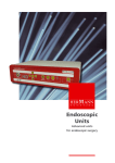
User Manual – integration of Control4
system with wireless system Moeller
XComfort
User Manual – integration of Control4 system with wireless system Moeller XComfort ............................................... 1
Driver name and version ................................................................................................................................................................... 2
Introduction................................................................................................................................................................................................... 3
Benefits ..................................................................................................................................................................................................... 3
Driver main features ............................................................................................................................................................................ 3
How to connect Moeller XComfort wireless system to Control4 system ............................................................................. 5
Set up procedure .................................................................................................................................................................................. 5
Configuration of Moeller XComfort system using the MRF sostware ............................................................................. 5
Export of configuration file from configuration software MRF .......................................................................................... 6
Adding the Moeller CI driver to device list in Composer Pro ............................................................................................. 7
Configuration of Moeller CI driver in Composer Pro ............................................................................................................. 7
Options for improving Moeller datapoint status reporting ......................................................................................................... 8
Option - Status refresh after the scene execution.......................................................................................................................... 8
Option - Status refresh running in background .............................................................................................................................. 8
Use of the driver in Composer Pro....................................................................................................................................................... 9
Dimmed light ......................................................................................................................................................................................... 9
Relay control........................................................................................................................................................................................ 10
Blinds control ...................................................................................................................................................................................... 11
Scenes (SCENE) contained in XComfort system .................................................................................................................... 12
Light scenes .................................................................................................................................................................................................. 12
General type scenes .................................................................................................................................................................................. 13
Inputs (binary) ..................................................................................................................................................................................... 14
Temperature sensing ....................................................................................................................................................................... 15
Processing the push of the button event ................................................................................................................................ 15
Error messages and error states events .......................................................................................................................................... 17
Driver operation during loss of connection with XComfort system ............................................................................ 18
Drivers diagnostic mode ................................................................................................................................................................. 19
List of XComfort parts supported by driver ................................................................................................................................... 20
Attachement: Auxiliarry Drivers .......................................................................................................................................................... 21
Driver of relay controlled light - Relay light ........................................................................................................................... 21
YATUN, s.r.o. | Tel.: +420 222 364 491
Litevská 8, Praha 100 00, Czech Republic
1 z 21
www.yatun.cz
www.control4.cz
Driver of dimmer controlled light - Generic dimming light ............................................................................................. 21
Driver name and version
Device Type
Other
Name
Moeller CI
Manufacturer
Moeller
Creator
YATUN
Created Date (version)
09/06/2009
Driver file name automation_232_moeller_ckoz_0003.c4i
Version of Moeller CI interface module compatible firmware CKOZ-00-03: 2.12
YATUN, s.r.o. | Tel.: +420 222 364 491
Litevská 8, Praha 100 00, Czech Republic
2 z 21
www.yatun.cz
www.control4.cz
Introduction
Driver allows connection of XComfort wireless system modules (sensors, switches, relays, dimmers, Room Manager
and Home Manager units) to Control4 system. To connect Moeller XComfort modules system with bidirectional
wireless communication to system control4 is used original Moeller wireless interface CKOZ-00-03.
Use of Moeller XComfort modules with Control4 system provide benefit of general compatibility with European
mains installation accessories – mainly flush wall mount boxes.
Control4 system provides visualization of status of lights, blinds and other home automation devices (gates, garage
door controls...) including temperatures, humidity and energy consumption measurements. Control4 system then
also allows manual control using the graphical user interfaces (TV on screen, touch panels) and remote control.
Bidirectional communication with all Moeller XComfort modules allows add full range of home automation
functions to Moeller system ( A/V multi-room system volume control from Moeller wireless wall mount switches
etc.)
Moeller wireless interface module type CKOZ-00-03 connects to Control4 Home controller units using the RS232
port. In one installation it is possible to use multiple CKOZ-00-03 modules One CKOZ-00-03 enables to connect
max. 99 Moeller wireless modules (datapoints).
Number of Moeller wireless modules (datapoints) connected to Control4 system is not limited by driver, only by
available system processing power (for larger installation recommended to use HC1000 Home controller) which
has to be sufficient to provide appropriate system response time for user.
Benefits
•
Easy integration of existing or new wireless Moeller XComfort electrical installation system in to
comfortable A/V and home automation and control system
•
Adding of cost effective and comfortable visualization and control to Moeller XComfort electrical
installation system
•
Easy control of lights, blinds, gates, temperature from wireless remote control, wireless or fixed touch
panels or TV onscreen menu
•
Control, integration and synchronization of light and A/V medial scenes
•
Integration of XComfort system, A/V system, CCTV, Intrusion detection system in to one seamlessly
operating and controlled system
•
Heating and air-conditioning control from remote control, TV, touch screen panels or via SMS and internet
•
Complete supervision and control of whole system (lights, heating, CCTV, security… ) from web interface
over Internet from any PC or mobile phone with browser ( http://my.control4.com)
Driver main features
Function
Type of processing tool
Processing of push of button/switch
(Event + variables)
Control of output relays On/Off + info on status change
(Connection)
Processing of input contacts (battery + 230 V types)
(Connection)
Dimmer control
(Connection + generic dimmer driver)
Periodic temperature readout (preconfigured in MRF)
(Connections)
Triggering scenes (SCENE) preset in XComfort system
(Connection to relay)
Supervision of modules status (signal strength, battery status)
(Event + variables)
YATUN, s.r.o. | Tel.: +420 222 364 491
Litevská 8, Praha 100 00, Czech Republic
3 z 21
www.yatun.cz
www.control4.cz
Reporting communication Errors
YATUN, s.r.o. | Tel.: +420 222 364 491
Litevská 8, Praha 100 00, Czech Republic
(Event+string variables)
4 z 21
www.yatun.cz
www.control4.cz
How to connect Moeller XComfort wireless system to
Control4 system
Set up procedure
1.
Configuration of network of XComfort wireless modules using the Moeller MRF software
2.
Connection and configuration of interface modules CKOZ-00-03 using the Moeller MRF software.
a.
CKOZ-00-03 module provides communication only with XComfort modules which are directly
visible to it (within CKOZ-00-03 communication range)!!! Datagrams (communication) to CKOZ-0003 module from other wireless modules in the system cannot be routed through actor modules or
repeaters!!!
b. In case of need of coverage of larger area it is possible to use multiple CKOZ-00-03 modules so it
provides required wireless coverage of whole house/site and brings all modules within
communication range of individual CKOZ-00-03 modules.
3.
Using the Moeller MRF software, export the final configuration (in to text file) of each CKOZ-00-03 module.
4.
Connect CKOZ-00-03 modules to RS-232 ports of Control4 Home controller (Control4 IO extenders,
GlobalCaché modules etc.).
a.
In case of connection of CKOZ-00-03 modules to GlobalCaché RS232 port extender or other, set
the port parameter appropriately (with GlobalCaché by web interface etc).
b. RS-232 port parameters used by driver: speed 57kbps, flow control: None, data bits: 8, stop bits: 1,
Parity: None.
5.
Add Moeller CI driver in to Control4 project using configuration software Composer Pro.
6.
Paste configuration data (from text files exported from MRF software) in to corresponding CKOZ-00-03
modules drivers (in Composer Pro software menu item System Design – folder tab Properties).
7.
Set up Connections and further configure all XComfort modules accessible via CKOZ-00-03 module.
8.
Set up in Composer Pro software, menu item Programming handling of Events from XComfort modules
(contacts closure/opening, temperature processing low battery…).
Configuration of Moeller XComfort system using the MRF software
All modules of XComfort system which should be monitored/controlled by Control4 system MUST be in the MRF
configuration software linked by “connection” to CKOZ-00-03 interface module.
Scenes (SCENES) in Moeller configuration program MRF are created automatically, when multiple modules are
linked to one datapoint number.
Scenes (SCENES) in Moeller configuration program MRF act as if controlled by pushbutton (short push up/down –in
Control4 mapped as relay).
Long push of the button is not supported in Control4. (Also is NOT supported a SCENE mapped to long push of
the button).
NOTE:
System Control4 can process as indication of different type of event quick double push of XComfort
pushbutton (binary input) using the Programming functions counting and timer. See details further.
YATUN, s.r.o. | Tel.: +420 222 364 491
Litevská 8, Praha 100 00, Czech Republic
5 z 21
www.yatun.cz
www.control4.cz
Export of configuration file from configuration software MRF
After configuration of all Moeller modules (datapoints) which should be used in Control4 system, it is necessary for
each CI module CKOZ-00-03 to export file with descriptions of the modules. Contents of these files are then
transferred in to Control4 Home controller via configuration program Composer Pro.
File with configuration data is created in Moeller configuration program by click to the right
mouse button when cursor is placed on icon of CKOZ-00-03 interface.
Following window is displayed.
Choose the option “Create list of Datapoints”. This displays following window with choice of location where the file
with configuration should be saved.
WARNING: File with configuration data MAY NOT be edited!! No characters may be added to the file (end of line,
tabulators etc.). For viewing of this files may be used only editors, which do not modify its contents by
adding characters!! Files use only LF at the end of line and some editors modify it to CRLF. Can be used
for example Notepad from MS Windows.
YATUN, s.r.o. | Tel.: +420 222 364 491
Litevská 8, Praha 100 00, Czech Republic
6 z 21
www.yatun.cz
www.control4.cz
Example of displayed contents of configuration file:
Adding the Moeller CI driver to device list in Composer Pro
Copy the Moeller driver file to directory Documents/Control4/Drivers created by Composer Pro in directory of
currently logged user. Then run (or restart) Composer Pro.
Using menu option „Manage drivers“add Moeller driver to „My Drivers“list. It appears there in folder “Others”.
Now you can add the Moeller driver
to list of devices in the project.
For each used Moeller CI interface module CKOZ-00-03 it is necessary to add one driver. To each CI module it is
necessary to set its connection via RS-232 port.
Configuration of Moeller CI driver in Composer Pro
When driver is added in to list of devices in the project, select it and click to the folder tab “Properties” in the
middle window “Properties”. Following window gets displayed:
Open (click) field named „Datapoints“and copy the contents of the exported configuration from MRF. Contents of
the exported configuration file may not be modified – it must be copied in identical form and contents using Ctrl+C
and Ctrl + V !!! After configuration data is pasted in to the field, confirm it by click to the button „Set“displayed
right to the Datapoint field.
YATUN, s.r.o. | Tel.: +420 222 364 491
Litevská 8, Praha 100 00, Czech Republic
7 z 21
www.yatun.cz
www.control4.cz
NOTE:
If there is more interface modules CKOZ-00-03 used in the project, it is necessary to paste appropriate
unique configuration file (list of datapoints).
In the folder tab „Documentation“middle window Properties is brief description of configuration and use of driver
in English.
In the folder tab „Lua“middle window Properties are shown communication data in case there is activated option
Debug.
In case of need it is possible to display diagnostic data - activate option Debug, see the paragraph “Drivers
diagnostic mode”.
Once the configuration of the driver is completed and it is possible to proceed in the Composer Pro sections A/V
Connections and Programming to work with relays, actors, sensors, temperatures from wireless Moeller system.
Options for improving Moeller datapoint status reporting
Interface module CKOZ-00-03 has limited memory and processing speed. Outgoing messages to
modules has highest communication priority in comparison to lower communication priority of returned
status messages. Therefore when larger scene is activated it may happen that some incoming/returned
status messages maybe dropped due its lower priority in favor of outgoing messages. Status messages
dropped by CKOZ-00-03 module cannot reach Control4.
Option - Status refresh after the scene execution
Enabling driver property item „Request status after scene performed „activates automatically after each scene (here
is understood scene defined in XComfort system and exported in to Control4) polling for status of all modules. Each
module is polled until it doesn’t respond. This provides more reliable status reporting in control of larger scenes.
Option - Status refresh running in background
Enabling driver property item „Request status when idle“activates process of automatic polling of all Moeller
modules any time when driver is idle. Every 10 seconds is sent poll to another module in endless cycle. This allows
status synchronization also for Moeller modules which temporarily did not respond to CKOZ-00-03 module or did
not manage to get through their status messages.
NOTE Status synchronization by polling works only with modules powered by mains voltage 230 V (mainly relays,
dimmers, and blinds control). States of input contacts cannot be polled (function not supported by Moeller
protocol).
YATUN, s.r.o. | Tel.: +420 222 364 491
Litevská 8, Praha 100 00, Czech Republic
8 z 21
www.yatun.cz
www.control4.cz
Use of the driver in Composer Pro
Driver for CI module CKOZ-00-03 enables Control4 system to use connected Moeller XComfort wireless modules in
following ways:
Following modules use “Connections” section in Composer Pro.
Type of module
Type of Connection
Dimmer (XComfort system module)
GEN_DIMMER
Output relay (XComfort system module)
RELAY
Scenes control/SCENES (XComfort system scenes)
RELAY
Blinds control
5x RELAY (UP, DOWN, STOP, STEP UP, STEP
DOWN)
Input contact (XComfort system module)
CONTACT_SENSOR
Temperature sensor (XComfort system module)
THERMOMETER
Dimmed light
Control4 system can control diming of lights connected to XComfort system dimmers. This lights are displayed on
Control4 graphical user interfaces as icon of dimmed light (Yatun generic dimming Light). For each Moeller dimmed
light module has to be added to Control4 project one Yatun generic dimming Light driver. This generic driver is
then connected in Composer Pro from menu option Connections, folder Control A/V by Connection type
GEN_DIMMER to l XComfort dimmer driver displayed in list available by click to icon of Connections of Moeller CI
driver. For details of „Yatun generic dimming light „driver, see Attachment “Generic dimming light”.
Example of screen with connection of light to dimmer:
NOTE: For Moeller dimmers are not available Ramp Level (speed and intensity of dimming) controls in Control4
Composer Pro software. Setting of Ramp Level parameters for Moeller dimmers has to be done in Moeller
configuration software MRF.
YATUN, s.r.o. | Tel.: +420 222 364 491
Litevská 8, Praha 100 00, Czech Republic
9 z 21
www.yatun.cz
www.control4.cz
Relay control
To control any device connected to Moeller relay output modules, is used on Control4 graphical user interfaces
icon of the device driver – lock, door, pump, blinds. (This driver icon is adds to the project in Composer Pro from
folder tab My Drivers, folder Motorization).
Each such a relay device driver has to be connected in Composer Pro menu options Connections, folder Control
A/V by Connection type RELAY to XComfort relay Data point/driver (displayed in list of Connections available by
click to icon of Moeller CI driver).
Examples of screen with Connections for control of Garage door by Moeller module relay output:
Control of Lights using the relay type output – (Connection type RELAY).
Control4 system can control lights connected to Moeller relay output modules. To show light controlled by relay
under Light icon and not Home icon (where all relay controlled devices are normally shown), it should be
represented by driver “Yatun relay light”.
This relay controlled lights can be displayed on Control4 user interfaces as icon of light driver. (Yatun relay light),
(this drivers icons adds to the project in Composer Pro from folder tab MyDrivers folder Lighting).
For each light connected to Moeller relay output module, there has to be added to Control4 project one “Yatun
relay light driver”. This generic driver is then connected in Composer Pro, menu options Connections, folder
Control A/V by Connection type RELAY to XComfort relay Datapoint/driver (displayed in list of Connections
available by click to icon of Moeller CI driver).
For details of „ Yatun relay light “driver, see Attachment “Driver of relay controlled light - Relay light”.
YATUN, s.r.o. | Tel.: +420 222 364 491
Litevská 8, Praha 100 00, Czech Republic
10 z 21
www.yatun.cz
www.control4.cz
Examples of screen with Connections for control of Light by Moeller module relay output:
Blinds control
To control blinds by Moeller XComfort module is used driver Single Relay Blind. Depending on the type of blinds
(according number of controlled functions/control inputs) it is possible to use up to 5 those drivers for one blind.
Each Single Relay Blind driver represents one type of action on controlled blind.
In blind Properties is choose type „Pulse Type „and leave pulse length time set to 500 ms (see example screen).
For each module controlling blinds is generated five RELAY type Connections, each representing one type of action
on controlled blind.
• UP
–blind to go up
• DOWN
– blind to go down
• STEP UP
– blinds lamellas/vanes to turn up
• STEP DOWN
– blinds lamellas/vanes to turn down
• STOP
– stop movement of blinds
YATUN, s.r.o. | Tel.: +420 222 364 491
Litevská 8, Praha 100 00, Czech Republic
11 z 21
www.yatun.cz
www.control4.cz
Length/duration of steps for STEP DOWN and STEP UP is defined in MRF software and stored in individual blind
controlling modules.
NOTE:
In comparison to native Control4 blind control driver is with Moeller XComfort blind control driver NOT
implemented graphic indication of blind movement on corresponding icon. Therefore during movement
of the blind, the blind movement will not be indicated by arrow on the blind icon.
Scenes (SCENE) contained in XComfort system
Light scenes
Light scenes, set up within the Moeller modules by MRF software can be controlled/activated from Control4 system.
In the same way can be controlled any scenes defined in the XComfort system.
NOTE:
Scenes from XComfort system are represented in Control4 as RELAY, where activation of scene is short
button press UP and DEactivation of scene is short button press DOWN (as used in the MRF logic). Long
button press for scenes is not supported in Control4 implementation.
In to the project list of devices in Composer Pro is added Light driver type „Yatun relay light“ and clearly named so
user can it easily identify as a scene control element. (For each scene defined within XComfort system which should
be controlled by icon of Light, there has to be added one driver type „Yatun relay light“. This driver is then
connected in Composer Pro, menu options Connections, folder Control A/V by Connection type RELAY to
XComfort relay Datapoint/driver (displayed in list of Connections available by click to icon of Moeller CI driver).
Scene is then controlled from the Programming section. Actions available for scenes are On, Off and Toggle.
YATUN, s.r.o. | Tel.: +420 222 364 491
Litevská 8, Praha 100 00, Czech Republic
12 z 21
www.yatun.cz
www.control4.cz
Example of control of Light scene „Scena1 –Vse Vyp“ (All OFF) by three button keypad. Scene is defined in
XComfort as Datapoint 99 (Scene)). On each press of first button on three button keypad scene state changes
(Turns OFF or turns ON).
General type scenes
Scenes, set up within the Moeller system and containing only relay type modules (optionally transformed to Light
by Relay Light gateway) can be controlled/activated from Control4 system using the icon
(added from folder tab My Drivers, folder Motorisation .
NOTE:
of relay driver
Scenes from XComfort system are represented in Control4 as RELAY, where activation of scene is short
button press UP and DEactivation of scene is short button press DOWN (as used in the MRF logic). Long
button press for scenes is not supported in Control4 implementation.
In to the project list of devices in Composer Pro is added relay driver type and clearly named so user can it easily
identify as a scene control element. (For each scene defined within XComfort system which should be controlled by
icon of relay, there has to be added one driver type Relay. This driver is then connected in Composer Pro, menu
options Connections, folder Control A/V by Connection type RELAY to XComfort scene Datapoint/driver (displayed
in list of Connections available by click to icon of Moeller CI driver).
Scene is then controlled from the Programming section. Actions available for scenes are On, Off and Toggle.
YATUN, s.r.o. | Tel.: +420 222 364 491
Litevská 8, Praha 100 00, Czech Republic
13 z 21
www.yatun.cz
www.control4.cz
Example of screen with connection „Scena6 – Vsechny rele vypnout. (ALL Relays OFF) “defined in XComfort as
Datapoint 99 (Scene)) to Relay driver.
Inputs (binary)
This section describes how use XComfort wireless modules with binary inputs (battery and mains/230V powered) in
Control4 system.
List of XComfort wireless modules- Datapoints containing binary inputs is shown in menu Connections folder tab
“Control A/V” when clicked to Moeller CI driver icon. Datapoints with binary inputs has type of Connection
“CONTACT_SENSOR”. From this list it is possible to make Connection to any driver representing device with binary
input possibility (Doorbell, Motion detector, Contact switch, Garage Door (with switch)…) available in the project
devices list.
Example screen, with Connection of binary input from XComfort Datapoint 7 to Doorbell and Connection of binary
input from XComfort Datapoint 8 to Motion Sensor.
When Connections are set up and Refresh Navigators (Shift+F5) operation is performed it is possible to use all
wireless inputs in Programming section and its status is show on-line on all Control4 user interfaces (TV navigator,
touch panels, remote control).
Speed of status change indication is limited only by throughput of XComfort system wireless network (approx.
800ms for one message) and number if simultaneously activated inputs (which adds load to XComfort RS232
interface module).
YATUN, s.r.o. | Tel.: +420 222 364 491
Litevská 8, Praha 100 00, Czech Republic
14 z 21
www.yatun.cz
www.control4.cz
NOTE:
In Composer Pro, menu item Programming, it is possible (using the function Timer and function of
counting in to variable) to process multiple activations of binary inputs (usually the pushbuttons
connected to it). As the speed of indication of activations of binary inputs depends on transmission
capacity/speed of XComfort network, the specific settings of timer periods and other processing
parameters vary depending on the site.
Temperature sensing
List of XComfort wireless modules-Datapoints containing temperature sensing capability is shown in menu
Connections folder tab “Control A/V” when clicked to Moeller CI driver icon. Depending on the number of
temperature sensing modules is shown number of Connections type “THERMOMETER”.
Connections type THERMOMETER is used for drivers “Temperature Consolidator” (simultaneous display of
temperatures from several sources), Software Thermostat (ON/OFF type thermostat) and similar ones.
Temperature updates periodically, depending on the period set in the XComfort modules by MRF configuration
software (update period typically set to several minutes).
Processing the push of the button event
Processing of notification about press of the button on the XComfort wireless modules (Button datapoint) is done
in Composer Pro using the script/program in section Programming using the Event „Button pressed „.
Programming script is triggered by Event „Button pressed „ and then follows evaluation of contents of numeric
variable BUTTON_DATAPOINT which determines on which module /datapoint button was pressed.
Further can be evaluated contents of text variable BUTTON_PART, which determines whether the button UP or
DOWN on the module /datapoint was pressed (variable contains strings DOWN or UP).
YATUN, s.r.o. | Tel.: +420 222 364 491
Litevská 8, Praha 100 00, Czech Republic
15 z 21
www.yatun.cz
www.control4.cz
Example screen, with script/program which evaluates button press. Event “Button pressed” triggers evaluation
whether Moeller RF module number 2 was activated (condition on variable BUTTON_DATAPOINT = 2), evaluation
whether button DOWN 2 was pressed (condition on variable BUTTON_PART = DOWN).
When both conditions are met, „Light“is turned ON.
YATUN, s.r.o. | Tel.: +420 222 364 491
Litevská 8, Praha 100 00, Czech Republic
16 z 21
www.yatun.cz
www.control4.cz
Error messages and error states events
In case that driver detects an error, it triggers (Event) "Error exception“. This Event can be processed by
Programming script. Additional information about error cause is stored by driver in to following variables:
LASTERROR contains error text description.
ERROR_TYPE contains type of error- error number used to further specify cause of error
ERROR__MSG contains further error specification dependent on the ERROR_TYPE contents
ERROR_DATAPOINT contains number of module /datapoint the error is related to.
Processing of contents of this variables allows properly identify error cause and choose the best response.
Example screen, with script/program triggered by Event "Error exception“. Further processing of contents of
variables ERROR_TYPE, ERROR_MSG, ERROR_DATAPOINT, and LASTERROR can identify error cause.
YATUN, s.r.o. | Tel.: +420 222 364 491
Litevská 8, Praha 100 00, Czech Republic
17 z 21
www.yatun.cz
www.control4.cz
List of Error messages
List of error types (values returned in ERROR_TYPE variable type Number):
Error type
Error number Description
ERROR_TYPE_UNKNOWN
=0
Unknown Error type
ERROR_TYPE_LOW_BATTERY
=1
Low battery
ERROR_TYPE_WEAK_SIGNAL
=2
Weak radio signal
ERROR_TYPE_DP_OOR
=3
Datapoint out of range
ERROR_TYPE_SENSOR_NO_DATA
= 10
Input module did not deliver data
ERROR_TYPE_MOELLER_GENERAL
= 20
General Moeller HW error
ERROR_TYPE_MOELLER_UNKNOWN
= 21
Unknown Moeller error
ERROR_TYPE_MOELLER_BUSY
= 22
Moeller HW busy
ERROR_TYPE_MOELLER_TIMEOUT
= 23
Moeller module did not respond to Moeller CI interface module
ERROR_TYPE_DRIVER_ERROR
= 100
Internal driver error (please report to driver supplier/restart
Control4 controller)
CONTENTS OF LASTERROR AND ERROR_MSG VARIABLES
Contains error text description and error specific data depending in Error Type.
When ERROR_TYPE - WEAK_SIGNAL
LASTERROR
ERROR_MSG
Received Signal Strength for datapoint xxx is weak.
WEAK (Weak radio signal)
Received Signal Strength for datapoint xxx is very weak. VERY WEAK (Very weak radio signal)
When ERROR_TYPE is LOW_BATTERY
LASTERROR
ERROR_MSG
Battery at device assigned to datapoint xxx is weak.
WEAK (battery partially discharged)
Battery at device assigned to datapoint xxx is very weak. VERY WEAK (battery low /almost discharged)
Battery at device assigned to datapoint xxx is empty.
EMPTY (battery completely discharged/empty)
Driver operation during loss of connection with XComfort system
In case of loss of communication between Control4 driver and XComfort system (for example due loss of power of
XComfort system or disconnected RS232 cable to XComfort interface, driver waits for communication to restore
and when communication with XComfort system is established again driver continues in operation.
During period of communication loss with XComfort system:
•
It is possible to notify user about this situation;
•
Input modules/sensors states are not updated;
•
Commands from control to XComfort output modules are not executed/not buffered;
•
System Control4 shows last known states of binary input modules;
•
System Control4 shows last known temperatures from temperature sensing modules.
YATUN, s.r.o. | Tel.: +420 222 364 491
Litevská 8, Praha 100 00, Czech Republic
18 z 21
www.yatun.cz
www.control4.cz
Drivers diagnostic mode
Driver allows in the folder Properties (menu item System Design) to set following diagnostic options:
Off
Logging of driver activity disabled
LOG
Log of driver activity is stored only to controller system log
Print
Log of driver activity is only displayed in the window Properties –folder tab “Lua”
Print +Log
Log of driver activity is stored to controller system and displayed in the window
Properties –folder tab “Lua”
NOTE: System Debug log is available in the file system of the controller which is running the Director in directory
“Log”.
NOTE: Both diagnostic options - Log and Print when activated are active for ¾ hour and then automatically turned
off, to prevent overflow of dedicated area of Home controller system disk. Maximum capacity of disc area for
diagnostic log is 5 MB.
To activate debug options, in ComposerPro select „System design (bottom left), then select folder tab „Properties“
in the middle window of driver properties window in the field „Debug Mode“ choose option „Print“, “Log” or „Print
and Log“. Selected choice confirm by click to the temporarily shown button “Set” on the right.
This activates on-line display of driver communication data. Data are shown under the Lua” folder tab in the middle
section of driver properties window in the field “Lua Output”.
Diagnostic data contain commands, periodic temperature readings and error texts which can help to identify cause
of problem or check whether driver communicates with XComfort system.
NOTE: By sending the contents of “Lua Output” field by email to supplier simplifies identification of encountered
problem.
YATUN, s.r.o. | Tel.: +420 222 364 491
Litevská 8, Praha 100 00, Czech Republic
19 z 21
www.yatun.cz
www.control4.cz
List of XComfort modules supported by driver
Communication interface
CKOZ-00/03 (CI module serves as interface to Control4)
Wireless switch 8 A/230 VAC
CSAU-01/01
Wireless switch, dry contact 8 A/230 VAC
CSAU-01/02
Wireless switch, double 6 A/230 VAC
CSAU-01/03
Dimmer 40–500 W
CDAU-01/01
Dimmer 40–250 W
CDAU-01/02
Dimmer 0–125 W
CDAU-01/03
Blinds control, safety func. 6 A/230 VAC
CJAU-01/02
Blinds control 6 A/230 VAC
CJAU-01/03
Two binary inputs 230 V 2x 230 VAC
CBEU-02/01
Two binary inputs , battery powered
CBEU-02/02
Two temperature sensors 2x -50 to +180 °C
CTEU-02/01
Switched Wall plug 8 A/230 VAC
CSAP-01/02
Dimmed Wall plug 250 W
CDAP-01/02
Analogue output 0–10 VDC
CAAE-01/01
Analogue output 1-10 VDC
CAAE-01/02
Push button surface mount-2 buttons
CTAA-01/01 (also CTAA-01/03)
Push button surface mount-4 buttons
CTAA-02/01 (also CTAA-02/03)
Push button surface mount-8 buttons
CTAA-04/01 (also CTAA-03/03)
PIR motion detector 110° range=12 m / h=2,2 m
CBMA-02/01
Under preparation
Home Manager
CHMU-00/02
Room Manager
CRMA-00/01 a CRMA-00/02
Room thermostat 0 to 40°C
CRCA-00/04
Room thermostat with humidity sensor
CRCA-00/05
Dual analogue input
CAEE-02/01
Dual pulse input (for consumption meters)
CIZE-02/01
Consumption meter -flush mount
CEMU-01/02
Consumption meter –Wall plug type
CEMP-01/12
YATUN, s.r.o. | Tel.: +420 222 364 491
Litevská 8, Praha 100 00, Czech Republic
20 z 21
www.yatun.cz
www.control4.cz
Attachment: Auxiliary Drivers
Driver of relay controlled light - Relay light
For proper allocation of device of Light type but controlled by relay has to be used driver „Yatun relay light“
Otherwise would light controlled by relay be displayed under the “Home” category/icon and not “Lights” where it
belongs.
This driver „Yatun relay light“has to be added to project device list in Composer Pro program. It creates icon which
can be linked in Connections - ControlA/V by Connection type RELAY to output contact of any device equipped
with output relays.
For each output relay contact which should control Light and which Icon should be show on TV, touch panel or
remote control as Light has to be created one driver „Yatun relay light“.
Naming of driver „Yatun relay light“should correspond to the design/use/location of controlled light.
„Yatun relay light“‘driver is available from supplier of Control4 Moeller driver– in knowledge database or FTP.
Driver of dimmer controlled light - Generic dimming light
For proper allocation of device of Light type controlled by other manufacturer dimmer than Control4 has to be
used driver „Yatun generic dimming light“. This allocated the dimmer correctly in to “Lights” category/icon in
Control4 UIs where it belongs.
This driver „Yatun generic dimming light“has to be added to project device list in Composer Pro program. It creates
icon which can be linked in Connections - ControlA/V by Connection type GEN-DIMMER to dimmer output of any
manufacturer.
For each dimmer output ( from other manufacturers) which should control Light and which Icon should be shown
on TV, touch panel or remote control as Light has to be created one driver „Yatun generic dimming light“
Naming of driver „Yatun generic dimming light“should correspond to the design/use/location of controlled light.
„Yatun generic dimming lights „driver is available from supplier of Control4 Moeller driver– in knowledge database
or FTP.
YATUN, s.r.o. | Tel.: +420 222 364 491
Litevská 8, Praha 100 00, Czech Republic
21 z 21
www.yatun.cz
www.control4.cz