1
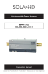
Sola/Hevi-Duty S3K Series Mini-Tower UPS
GUIDE SPECIFICATIONS
700VA to 1600VA – 120V models
Single - Phase Uninterruptible Power Supply Systems
1.0
1.1
GENERAL
SUMMARY
This specification defines the electrical and mechanical characteristics and requirements for a continuousduty single-phase, solid-state, uninterruptible power system. The uninterruptible power system, hereafter
referred to as the UPS, will provide high-quality AC power for sensitive electronic equipment loads.
1.2
STANDARDS
The UPS is designed in accordance with the applicable sections of the current revision of the following
documents. Where a conflict arises between these documents and statements made herein, the statements
in this specification will govern.
120V Units
UL 1778, c-UL listed (to CSA 22.2 No. 107.1)
FCC Part 15, Subpart B, Class B
ANSI C62.41, Category A, Level 3 (IEEE 587, Category A);
EN61000-4-5, Level 3, Criteria B
EN61000-4-2, Level 3, Criteria B
EN61000-4-3, Level 3, Criteria A
EN61000-4-4, Level 4, Criteria A
EN61000-4-6
EN61000-3-2
EN61000-3-3
1.3.
SYSTEM DESCRIPTION
1.3.1
Modes of Operation
The UPS is designed to operate as a line-interactive system in the following modes:
A. Normal - The critical AC load is continuously supplied with filtered power. The battery
charger maintains a float-charge on the battery.
B. Voltage Boost/Buck - During input power source abnormalities (sags and swells), the AC
output power is corrected by means of boost (sag correction) or buck (swell correction)
compensation taps. Operation of the compensation taps automatically maintains the proper
output voltage for the connected critical equipment. The compensation taps is designed for
indefinite operation to their limits. Operation of the compensation taps will not discharge the
battery.
C. Recharge - Upon restoration of utility / mains AC power, after a utility / mains AC power
outage and complete or partial battery discharge, the unit automatically restarts and resumes
supplying power to the critical AC load; and the battery charger recharges the battery.
D. Battery - When the input power source exceeds the parameters defined in section 1.3.3.1, the
critical AC load is supplied power by the inverter, which obtains its power from the battery.
Typical detection and transfer time is 4-6 ms.
E. Battery Start- The UPS is capable of starting without input power. The unit starts up and
operates from the battery, with output frequency the same as the last operating frequency.
1.3.2
Design Requirements
A. Voltage: Input/output voltage specifications of the UPS are:
Gross Automation (877) 268-3700 · www.solahevidutysales.com · [email protected]
1
Gross Automation (877) 268-3700 · www.solahevidutysales.com · [email protected]
Input: 0-165 VAC, 60/50 Hz auto-sensing, single-phase, 2-wire-plus-ground.
Output:120VAC ±10%, 60/50 Hz, single-phase, 2-wire-plus-ground.
B. Output Load Capacity: Maximum specified output load capacity of the UPS, regardless of
load power factor, is:
700VA / 480W
1000VA / 750W
1600VA / 1200W
C. Internal Battery: The battery consists of valve regulated, non-spillable, maintenance-free,
sealed, lead-acid cells. The battery is user replaceable and hot swappable.
D. Battery Reserve Time (typical at full load) with ambient temperature 77°F (25°C):
700VA: 5 Min.
1000VA: 3 Min.
1600VA: 3 Min.
E. Battery Recharge: The UPS contains a battery recharge rate designed to prolong battery life.
Recharge time is 4 hours typical to 90% capacity after a complete discharge into full resistive
load.
1.3.3
Performance Requirements
1.3.3.1 AC Input to UPS
A. Voltage Configuration: The UPS operates at these values without drawing power from the
batteries.
120 VAC nominal: single phase, 2-wire-plus-ground: 85 ─ 145 VAC (±3VAC),
Buck compensation: 133VAC (±3VAC)
Boost1 compensation: 107VAC (±3VAC)
Boost2 compensation: 95VAC (±3VAC)
B. Frequency: The UPS automatically senses the input frequency and operates within the
following frequency specifications without drawing power from the batteries.
50 or 60 Hz Auto Sensing (±0.5%)
C. Surge Protection: The 120 VAC units can withstand input surges of up to 320J without
damage per criteria listed in IEEE C62.41, Category A, Level 3.
D. Input Connections: The 120 VAC units have an attached input cord 6 feet (1.8 meters) in
length, measured between the inside edges of the connectors. The attached input cord has a
NEMA 5-15 plug.
1.3.3.2 AC Output
A. Voltage Configuration:
120 VAC, 60/50 Hz, single-phase, 2-wire-plus-ground. (Normal mode)
120 VAC, ±5% RMS prior to low battery warning; ±8% RMS after low battery warning
(Battery mode)
B. Voltage Regulation: ±10% steady state.
C. Frequency Regulation: +/-0.5% synchronized to utility / mains.
D. Load Power Factor Range: 0.6 lagging to 1.0 (unity).
E. Inverter Overload Capability: Overload Warning (visual and audible alarms) occurs
between 100%─109% of rated capacity, continuous duty. Shutdown occurs at the following
levels:
Gross Automation (877) 268-3700 · www.solahevidutysales.com · [email protected]
2
Gross Automation (877) 268-3700 · www.solahevidutysales.com · [email protected]
>110 ─ 165%; after 90 seconds (Normal mode)
>165 ─ 200%; after 60 seconds (Normal mode)
>200% - short-circuit; after 15 cycles (Normal mode)
>100 – 110%; after end of discharge (Battery mode)
>110%; after 30 seconds (Battery mode)
>120%; after 5 cycles (Battery mode)
>150%; after 1cycle (Battery mode)
F. Voltage Transient Response: ±15% in Normal mode for 0-100-0% loading of the UPS
rating, ±5% in Battery mode for 20-100-20% loading of the UPS rating.
G. Transient Recovery Time: To within ±8% of nominal voltage in < 2 cycles.
H. Efficiency: >95% (Normal mode)
>90% (Buck/Boost mode)
>70% (Battery mode)
1.4
ENVIRONMENTAL CONDITIONS
A. Ambient Temperature
Operating: 32oF ─ 104oF (0oC ─ 40oC) for altitudes 0 ─ 5,000 ft. (0 ─ 1500 meters) above sea
level
32°F ─ 95°F (0°C ─ 35°C) for altitudes 5000 ft ─ 10,000 ft (1500 ─ 3000 meters)
above sea level.
77o F (25oC) for optimum battery performance
Storage: 5°F ─ 104°F (-15°C ─ 40°C) with batteries
5oF ─ 122oF (-15oC ─ 50oC) without batteries
68oF (20oC) for optimum battery storage.
B. Relative Humidity
0 ─ 95% non-condensing.
C. Altitude:
3,000 m (10,000 ft. max.), without power derating when operated within the temperature specified
in section 1.4.A.
D. Audible Noise
Noise generated by the UPS during normal operation does not exceed 50 dBA.
E. Electrostatic Discharge
The 120 VAC units are able to withstand an electrostatic discharge compliant to EN61000-4-2,
level 3, Criteria B without damage and without affecting the connected load. The 230 VAC units
are able to withstand an electrostatic discharge compliant to EN61000-4-2, level 3, Criteria B
without damage and without affecting the connected load.
1.5
USER ACCESSORIES AND PACKAGING
The specified UPS system is supplied with one (1) user's manual. The manual includes installation
drawings and instructions, a functional description of the equipment, safety precautions, illustrations,
operating procedures, and general maintenance guidelines. The UPS is also supplied with one (1) UPS
Gross Automation (877) 268-3700 · www.solahevidutysales.com · [email protected]
3
Gross Automation (877) 268-3700 · www.solahevidutysales.com · [email protected]
Monitoring Software CD (UPSMON bundle version), one (1) RS232 Communications Interface Cable
with DB9 Connectors at both ends (6 feet, 1.8m) and one (1) RJ-11 cord (6 feet, 1.8m).
1.6
WARRANTY
The manufacturer warrants the UPS against defects in materials and workmanship for one (1) year.
1.7
QUALITY ASSURANCE
1.7.1
Manufacturer Qualifications
Sola/Hevi-Duty provides more than twenty years experience in the design, manufacture, and
testing of solid-state UPS systems and the company is certified to ISO 9001.
1.7.2
Factory Testing
Before shipment, the product is tested to assure compliance with the specification.
2.0
2.1
PRODUCT
FABRICATION
All materials and components making up the UPS are new, of current manufacture, and have not been in
prior service except as required during factory testing. All relays are provided with dust covers.
2.1.1
Wiring
Wiring practices, materials, and coding are in accordance with the requirements of the standards
listed in section 1.2. All wiring is copper.
2.1.2
Cabinet
The UPS unit comprised of: TVSS & EMI/RFI Filters, Relay, Automatic Voltage Regulator,
Battery Charger, Battery consisting of the appropriate number of sealed battery cells and Inverter
is housed in a mini-tower NEMA type 1 enclosure. The UPS cabinet is injection-molded standard
color. Dimensions and weights are:
UNIT
2.1.3
UNIT DIMENSIONS
WEIGHT
W x D x H in (mm)
lbs (kg)
700VA
5.5 x 17.2 x 8.3 (140 x 436 x 210)
31.9 (14.5)
1000VA
5.5 x 17.2 x 8.3 (140 x 436 x 210)
34.8 (15.8)
1600VA
8.9 x 17.7 x 6.7 (226 x 450 x 170)
66 (30)
Cooling
The UPS is forced air cooled by variable speed internal fan(s), which operate only when needed to
maintain internal temperatures to acceptable levels. Air intake is through the front of the unit and
exhausted out the rear of the unit.
2.2
COMPONENTS AND OPERATION
2.2.1
Input Protection
The UPS has built-in protection against undervoltage, overcurrent, and overvoltage conditions
including low-energy lightning surges introduced on the primary input power source. The UPS is
provided with an input circuit protector. The UPS will withstand input surges without damage per
criteria listed in IEEE C62.41, Category A, Level 3. Additionally, the UPS is supplied with one
Gross Automation (877) 268-3700 · www.solahevidutysales.com · [email protected]
4
Gross Automation (877) 268-3700 · www.solahevidutysales.com · [email protected]
pair of Data Line Protection Connectors to provide phone, fax or modem line surge protection via
RJ-45 connectors. These Data Line Protection Connectors provide transmission for 10/100 BaseT Ethernet connections.
2.2.2
Battery Recharge
The UPS contains a battery recharge rate designed to prolong battery life. The battery is constant
voltage charged to recharge and maintain the battery in a fully charged state. Recharge time is 4
hours maximum to 90% rated capacity after discharge into full resistive load.
2.2.3
Output Protection
For output faults including short circuits and overloads, the UPS is protected by the input circuit
protector during Normal mode and by electronic current limiting during Battery mode.
2.2.4
Overload
The UPS is capable of supplying power for overloads exceeding 100% and up to 110% of full
load rating, continuously. A visual indicator and audible alarm indicate overload operation. For
greater current demands, the UPS employs circuit protector and electronic current-limiting
protection to prevent damage to components. The UPS is self-protecting against any magnitude of
connected output overload. The UPS control logic senses and disconnects the UPS from the
critical AC load and clears the protective device during Normal mode.
2.2.5
Output Frequency
An oscillator controls the output frequency of the UPS. The oscillator maintains the output
frequency to + 0.5 Hz of nominal when not synchronized to the utility/mains source.
2.2.6
Battery Over-Discharge Protection
To prevent battery damage due to excessive discharge levels, the UPS control logic automatically
monitors the battery voltage and load level and switches off the output at the predetermined
battery shutdown voltage set point.
2.2.7
Display and Controls
2.2.7.1 General
The UPS is provided with a microprocessor-based unit status and control display
designed for convenient and reliable user operation. The status and alarm indicators are
displayed on a status indicator display.
2.2.7.2 System Indicators
There is a row of Load Level indicators that display the approximate electrical load
placed upon the UPS. There is also a row of Battery Level indicators that display the
approximate battery capacity. Finally, there are seven (7) status indicators on the UPS as
described below:
The “Line Normal” indicator (GREEN LED, front panel) illuminates when
utility power is normal.
The “Site Wiring Fault” indicator (RED LED, rear panel) illuminates when the
UPS detects a Site Wiring Fault.
The “Back Up” indicator (GREEN LED, front panel) illuminates when the UPS
is operating on battery and the UPS will produce slow beeping sound.
The “Replace Battery” indicator (RED LED, front panel) illuminates when the
internal battery is discharged and must be replaced. PLEASE NOTE THAT
ONCE THE BATTERY HAS DISCHARGED TO UNDER 25% OF RATED
CAPACITY, THE UPS WILL PRODUCE A RAPID BEEPING SOUND.
Gross Automation (877) 268-3700 · www.solahevidutysales.com · [email protected]
5
Gross Automation (877) 268-3700 · www.solahevidutysales.com · [email protected]
The “Overload” indicator (RED LED, front panel) illuminates when the loads
connected to the UPS exceed the UPS’s rated capacity. At the same time, the
UPS will produce a continuous beeping sound as long as the unit is overloaded.
The “Buck AVR” indicator (YELLOW LED, front panel) illuminates when the
UPS is correcting a high utility voltage condition and providing normal voltage
to the connected loads.
The “Boost AVR” indicator (YELLOW LED, front panel) illuminates when the
UPS is correcting a low utility voltage condition and providing normal voltage
to the connected loads.
2.2.7.3 ON/TEST & OFF Buttons
ON - When the UPS is Off, pressing the ON/Test button for more than one (1) second
will start the UPS. The UPS is capable of starting on battery (battery start).
The “ON/TEST” button also activates the self-test function.
OFF Button - When the UPS is on (in either Normal or Battery mode), pressing
the OFF button for more than one (1) second will shut down the UPS.
2.2.8
Internal Battery
Valve regulated, non-spillable, lead-acid cells are used as a stored-energy source for the specified
UPS system. The battery is housed internal to the UPS cabinet, and sized to support the inverter at
rated load and power factor, with ambient temperature of 77 o F (25 o C) for a minimum of
3 minutes reserve time. The expected life of the battery is 3 - 5 years or 250 complete discharge
cycles.
2.2.9
Data Line Protection Connectors
Data line (in and out) connectors are on the rear of the UPS and provide transient voltage
surge suppression (TVSS) for Phone/Fax/DSL/Internet/Modem devices.
2.2.10
Output Distribution
Output distribution is integral to the UPS and is located on the rear of the unit.
UNIT
2.2.11
OUTLETS
700VA & 1000VA
(4) NEMA 5-15R
1600VA
(6) NEMA 5-15R
Communications
The UPS has a DB-9 (9 pin female) connector on the rear to allow UPS status communications
with a computer system running UPSMON software. The DB-9 is capable of supplying serial
communication, on battery and low battery signals.
The pin out configuration of the DB9 connector is:
Pin
1
2
Assignment Description
Not used
Power Failure, Hi to Lo signal produced
Gross Automation (877) 268-3700 · www.solahevidutysales.com · [email protected]
6
Gross Automation (877) 268-3700 · www.solahevidutysales.com · [email protected]
3
4
5
6
7
8
9
Not used
Reference ground for Pins 2 and 5
Low battery, Hi to Lo signal produced
RS-232 data output (R X D) *
Reference ground for Pin 6
Not used
RS-232 data output
NOTE: Pins 2 and 5 are open collector outputs that must be pulled up to a
common reference supply no greater than +40VDC, 25mA, non-inductive.
Use only Pin 7 as the common.
* The UPS will shut down when a high RS-232 level is sustained on Pin 6
for 0.36 seconds.
2.2.11.1
Any Mode Shutdown - Via Pins 5 & 6
When Pin 6 is shorted to Pin 5, the UPS output is shut Off regardless of what mode the
UPS is operating in. The UPS cannot be started as long as the pins are shorted. When the
short is removed, the UPS output can be enabled by pressing the ON/TEST button.
2.2.11.2
Battery Mode Shutdown—Via Pins 5 & 2
While the UPS is operating on battery (with no battery test in progress), a 5-12VDC
signal for 2 seconds or longer is required to signal a shutdown. Signals for less than 2
seconds are ignored
Gross Automation (877) 268-3700 · www.solahevidutysales.com · [email protected]
7
Gross Automation (877) 268-3700 · www.solahevidutysales.com · [email protected]