1
MODEL PCI-DIO-72/96/120
USER MANUAL
FILE: MPCI-DIO-120.D1i
Notice
The information in this document is provided for reference only. Portwell does not assume any liability
arising out of the application or use of the information or products described herein. This document may
contain or reference information and products protected by copyrights or patents and does not convey
any license under the patent rights of Portwell, nor the rights of others.
IBM PC, PC/XT, and PC/AT are registered trademarks of the International Business Machines
Corporation.
Printed in USA. Copyright 2001, 2005 by Portwell I/O Products Inc. All rights reserved.
WARNING!!
ALWAYS CONNECT AND DISCONNECT YOUR FIELD CABLING WITH
THE COMPUTER POWER OFF. ALWAYS TURN COMPUTER POWER OFF
BEFORE INSTALLING A CARD. CONNECTING AND DISCONNECTING
CABLES, OR INSTALLING CARDS INTO A SYSTEM WITH THE
COMPUTER OR FIELD POWER ON MAY CAUSE DAMAGE TO THE I/O
CARD AND WILL VOID ALL WARRANTIES, IMPLIED OR EXPRESSED.
2
Manual PCI-DIO-72/96/120
Warranty
Prior to shipment, Portwell equipment is thoroughly inspected and tested to applicable specifications.
However, should equipment failure occur, Portwell assures its customers that prompt service and support
will be available. All equipment originally manufactured by Portwell which is found to be defective will be
repaired or replaced subject to the following considerations.
Terms and Conditions
If a unit is suspected of failure, contact Portwell' Customer Service department. Be prepared to give the
unit model number, serial number, and a description of the failure symptom(s). We may suggest some
simple tests to confirm the failure. We will assign a Return Material Authorization (RMA) number which
must appear on the outer label of the return package. All units/components should be properly packed for
handling and returned with freight prepaid to the Portwell designated Service Center, and will be returned
to the customer's/user's site freight prepaid and invoiced.
Coverage
First Three Years: Returned unit/part will be repaired and/or replaced at Portwell option with no charge for
labor or parts not excluded by warranty. Warranty commences with equipment shipment.
Following Years: Throughout your equipment's lifetime, Portwell stands ready to provide on-site or in-plant
service at reasonable rates similar to those of other manufacturers in the industry.
Equipment Not Manufactured by Portwell
Equipment provided but not manufactured by Portwell is warranted and will be repaired according to the
terms and conditions of the respective equipment manufacturer's warranty.
General
Under this Warranty, liability of Portwell is limited to replacing, repairing or issuing credit (at Portwell
discretion) for any products which are proved to be defective during the warranty period. In no case is Portwell
liable for consequential or special damage arriving from use or misuse of our product. The
customer is responsible for all charges caused by modifications or additions to Portwell equipment not
approved in writing by Portwell or, if in Portwell opinion the equipment has been subjected to abnormal
use. "Abnormal use" for purposes of this warranty is defined as any use to which the equipment is
exposed other than that use specified or intended as evidenced by purchase or sales representation.
Other than the above, no other warranty, expressed or implied, shall apply to any and all such equipment
furnished or sold by Portwell.
3
Manual PCI-DIO-72/96/120
Table of Contents
Chapter 1: Introduction................................................................................................. 5
Figure 1-1: Block Diagram ...................................................................................... 8
Chapter 2: Installation................................................................................................... 9
Chapter 3: Option Selection ....................................................................................... 11
Chapter 4: Address Selection .................................................................................... 13
Chapter 5: Software .................................................................................................... 14
Chapter 6: Programming ............................................................................................ 15
Table 6-1: Address Registry Table ........................................................................ 15
Table 6-2: Control Register Bit Assignments ......................................................... 16
Programming Example............................................................................................ 18
Chapter 7: Connector Pin Assignments.................................................................... 20
Table 7-1: Connector Pin Assignments ................................................................. 20
4
Manual PCI-DIO-72/96/120
Chapter 1: Introduction
Features
•
Up to 120 Channels of Digital Input/Output.
•
All I/O Lines are Buffered on the Card.
•
Four and Eight Bit Ports are Independently Selectable for I/O on Each 24-Bit Group.
•
Hysteresis on Inputs and Pull-Up Resistors on I/O Lines. (Optional Pull-Downs.)
•
Interrupt and Interrupt-Disable Capability.
•
Tri-stateable I/O Ports Under Software Control.
•
+5V Supply Available to User.
•
Compatible with Industry Standard I/O Racks.
Applications
•
Automatic Test Systems.
•
Security Systems, Energy Management.
•
Robotics.
•
Relay Monitoring and Control.
•
Parallel Data Transfer to PC.
•
Sensing switch closures or TTL, DTL, CMOS Logic.
•
Driving Indicator Lights or Recorders.
This manual applies to Models 120, 96, and 72. The same printed circuit board is used for all three
models. The board is populated for 120 bits, 96 bits, and 72 bits respectively.
Each I/O line is buffered and capable of sourcing 32mA, or sinking 64mA. The board contains
Programmable Peripheral Interface chips type 8255-5 (PPI) to provide a computer interface to digital I/O
lines. Each PPI supports two 8-bit ports (A, B) and two 4-bit ports (Chi, Clow). Each port can be configured
to function as either input or output latches. The I/O line buffers (type 74ABT245) are configured
automatically by hardware logic for input or output according to the PPI 8255-5 Control Register direction
software assignment.
Outputs of the I/O buffers are pulled up through 10KΩ resistors to +5VDC. Optionally, your card may have
been ordered with the outputs pulled down to ground via 680Ω resistors. There is a description in the
Option Selection section of this manual that describes how to determine whether there are pull-ups or
pull-downs on your card.
The I/O buffers may be tristated under program control. If the BEN/TST jumper on the card is installed in
the BEN position, the I/O buffers are permanently enabled allowing transparent backwards compatibility.
However, if the jumper is placed in the TST position, enable/disable of the buffers is under software
control.
One I/O line of each group can be used to generate an interrupt. Interrupts are enabled by jumper
installation (IEN jumper) or by a combination of jumper installation and a digital input line for Bit C3 at
each 24-bit group.
5
Manual PCI-DIO-72/96/120
I/O wiring connections are via 50-pin headers on the board. This provides compatibility with OPTO-22,
Gordos, Potter & Brumfield, Western Reserve Controls, etc. module mounting racks. Every second
conductor of the flat cables is grounded to minimize crosstalk between signals. If needed for external
circuits, +5VDC power is available on each I/O connector at pin 49. If you use this power, we recommend
that you include a 1A fast blow fuse in your circuits in order to avoid possible damage to the host
computer.
The cards occupy 32 addresses within the PCI I/O space. The base address is assigned by the system.
Refer to the Option Selection Section of this manual for a detailed description.
6
Manual PCI-DIO-72/96/120
Specifications
Digital Input
•
Logic High:
2.0 to 5.0 VDC
•
Logic Low:
-0.5 to +0.8 VDC
•
Load:
±20 μA
Digital Output
•
Logic High:
2.0 VDC min., source 32 mA
•
Logic Low:
0.55 VDC max., sink 64 mA
•
Power Output: +5 VDC from computer bus (ext. 1A fast blow fuse recommended)
•
Power Requirements:
•
Size:
+5 VDC at 200 mA typical
12.2" long (310 mm)
Environmental
•
Operating Temperature Range:
0 °C. to 60 °C
•
Storage Temperature Range:
-50 °C. to +120 °C
•
Humidity:
0 to 90% RH, non-condensing
Utility software provided on diskette with these cards is an illustrated setup program, SETUP.EXE.
Interactive displays show locations and proper settings of jumpers to set up tristate control of the buffers
and the interrupt enable function. Another utility program on the diskette, PCIFind.EXE, can be used to
locate resources used by installed PCI-bus cards. Additionally, two sample programs and a utility driver
for use with VisualBASIC for Windows are provided. See the Software section of this manual for a
detailed description of the latter.
7
Manual PCI-DIO-72/96/120
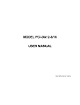
COMPUTER PCI BUS
TYPICAL OF EACH PPI (24 BITS)
PORT A
PCI
PPI
BUS
GROUP
PORT B
PORT C HI
PORT C LO
LOGIC
B
U
F
F
E
R
S
C
O
N
N
E
C
T
O
R
EXTERNAL
INTERRUPT
INTERRUPT
ENABLE
Figure 1-1: Block Diagram
8
Manual PCI-DIO-72/96/120
Chapter 2: Installation
A printed Quick-Start Guide (QSG) is packed with the card for your convenience. If you’ve already
performed the steps from the QSG, you may find this chapter to be redundant and may skip forward to
begin developing your application.
The software provided with this card is on CD and must be installed onto your hard disk prior to use. To
do this, perform the following steps as appropriate for your operating system.
Configure Card Options via Jumper Selection
Before installing the card into your computer, carefully read Chapter 3: Option Selection of this manual,
then configure the card according to your requirements. Our Windows based setup program can be used
in conjunction with Chapter 3 to assist in configuring jumpers on the card, as well as provide additional
descriptions for usage of the various card options.
CD Software Installation
The following instructions assume the CD-ROM drive is drive “D”. Please substitute the appropriate drive
letter for your system as necessary.
DOS
1.
2.
3.
4.
Place the CD into your CD-ROM drive.
Type B- to change the active drive to the CD-ROM drive.
Type GLQR?JJ- to run the install program.
Follow the on-screen prompts to install the software for this board.
WINDOWS
1.
Place the CD into your CD-ROM drive.
2.
The system should automatically run the install program. If the install program does not run
promptly, click START | RUN and type BGLQR?JJ, click OK or press -.
3.
Follow the on-screen prompts to install the software for this board.
LINUX
1.
Please refer to linux.htm on the CD-ROM for information on installing under linux.
Caution! * ESD A single static discharge can damage your card and cause premature
failure! Please follow all reasonable precautions to prevent a static
discharge such as grounding yourself by touching any grounded
surface prior to touching the card.
9
Manual PCI-DIO-72/96/120
Hardware Installation
1.
2.
3.
4.
5.
6.
7.
8.
9.
10.
Make sure to set switches and jumpers from either the Option Selection section of this manual or
from the suggestions of SETUP.EXE.
Do not install card into the computer until the software has been fully installed.
Turn OFF computer power AND unplug AC power from the system.
Remove the computer cover.
Carefully install the card in an available 5V or 3.3V PCI expansion slot (you may need to remove
a backplate first).
Inspect for proper fit of the card and tighten screws. Make sure that the card mounting bracket is
properly screwed into place and that there is a positive chassis ground.
Install an I/O cable onto the card’s bracket mounted connector.
Replace the computer cover and turn ON the computer which should auto-detect the card
(depending on the operating system) and automatically finish installing the drivers.
Run PCIfind.exe to complete installing the card into the registry (for Windows only) and to
determine the assigned resources.
Run one of the provided sample programs that was copied to the newly created card directory
(from the CD) to test and validate your installation.
The base address assigned by BIOS or the operating system can change each time new hardware is
installed into or removed from the computer. Please recheck PCIFind or Device Manager if the hardware
configuration is changed. Software you write can automatically determine the base address of the card
using a variety of methods depending on the operating system. In DOS, the PCI\SOURCE directory
shows the BIOS calls used to determine the address and IRQ assigned to installed PCI devices. In
Windows, the Windows sample programs demonstrate querying the registry entries (created by PCIFind
and NTIOPCI.SYS during boot-up) to determine this same information.
10
Manual PCI-DIO-72/96/120
Chapter 3: Option Selection
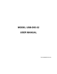
Refer to the illustrated setup programs on the diskette provided with the card when reading this section of
the manual. Also, refer to Figure 3-1, Option Selection Map on the following page.
External interrupts are accepted on pin 9 (Bit C3) of each I/O connector and gated (if the jumper is in the
INP position) by bit C7 at pin 1. The interrupt signal should be a rising edge and is latched. An interrupt
can also be generated by software by toggling bit 3 (low then high) of port C of any group. External (or
internal) interrupts may be gated 'off' by software if the jumper is in the INP position by setting bit C7 high.
Your program must enable/disable interrupts, interrupts are disabled at 'power up'. You enable interrupts
globally by writing any value to Base Address +1F hex. Also, you can clear and disable interrupts by
writing any value to Base Address +1E hex. Interrupts are enabled if the IEN jumper (one for each 24-bit
port) is installed, or enabled by program if the corresponding INP jumper is installed and I/O connector pin
1 (Bit C7) is low. Interrupts are disabled at each 24-bit group if (a) neither the IEN or INP jumper is
installed, or (b) if the INP jumper is installed but I/O connector pin 1 (Bit C7) is held high.
These cards provide a means to enable/disable the tristate I/O buffers under program control. If the
BEN/TST jumper on the card is installed in the BEN (buffer enable) position, the I/O buffers are enabled.
However, if the jumper is placed in the TST (tristate) position, enable/disable of the buffers is under
software control as described in the Software Programming section of this manual.
As pointed out in Chapter 1 of this manual, outputs of the I/O buffers may be either pulled-up to +5VDC or
pulled down to ground. You can determine how your card is configured by inspecting positions labeled
VCC and GND. You will see three solder pads at each of those. (Those positions are shown on the
Option Selection map for location purposes only. The pads/jumpers are actually on the wiring side of the
board.) If your card is configured for pull-down, the etch between the top two pads will have been cut and
a wire jumper installed between the middle and the bottom pad.
The foregoing are the only manual setups necessary to use these cards. Input/Output selection is done,
via software, by writing to the PPI Control Registers as described in the Programming section of this
manual.
11
Manual PCI-DIO-72/96/120
Figure 3-1: Option Selection Map
12
Manual PCI-DIO-72/96/120
Chapter 4: Address Selection
These cards use one address space, and occupy 32 register locations. The 120-bit model requires 20
locations for I/O, the 96-bit model uses 16, and the 72-bit model uses 12 locations. These are defined in
the Port Address Selection Table in the Programming section of this manual.
PCI architecture is inherently plug-and-play. This means that the BIOS or Operating System determines
the resources assigned to PCI cards rather than you selecting those resources with switches or jumpers.
As a result, you cannot set or change the card's base address or IRQ level. You can only determine what
the system has assigned.
To determine the base address that has been assigned, run the PCIFind.EXE utility program provided.
This utility will display a list of all of the cards detected on the PCI bus, the addresses assigned to each
function on each of the cards, and the respective IRQs.
Alternatively, some operating systems can be queried to determine which resources were assigned. In
these operating systems, you can use either PCIFind or the Device Manager utility from the System
Properties Applet of the control panel. The card is installed in the Data Acquisition class of the Device
Manager list. Selecting the card, clicking Properties, and then selecting the Resources Tab will display a
list of the resources allocated to the card.
The PCI bus supports 64K of I/O address space, so your card's addresses may be located anywhere in
the 0000 to FFFF hex range.
PCIFind uses the Vendor ID and Device ID to search for your card, then reads the base address and
IRQ.
If you want to determine the base address and IRQ yourself, use the following information.
The Vendor ID for these cards is 494F. (ASCII for "IO")
The Device ID for the 72 is 0C68.
The Device ID for the 96 is 0C70.
The Device ID for the 120 is 0C78.
13
Manual PCI-DIO-72/96/120
Chapter 5: Software
Several programs are supplied to support these cards and to help you develop your application's
software. These programs are on the CD or diskette that comes with your card and are briefly described
in other portions of this manual. The following paragraphs contain additional information about the setup
program.
SETUP.EXE
This program is supplied as a tool for you to use in configuring jumpers on the card. It is menu-driven and
provides pictures of the card on the computer monitor. You make simple keystrokes to select the
functions. In turn, the pictures then change to show how the jumpers should be placed to effect your
choices.
The setup program is a stand-alone program that can be run at any time. It does not require the card to
be plugged into the computer for any part of the setup. The program is self-explanatory with operation
instructions and on-line help. (Of course, the card has to be installed to check the PCIFind utility.)
To run this program, at the DOS prompt, enter SETUP.EXE followed by the - key.
14
Manual PCI-DIO-72/96/120
Chapter 6: Programming
The 120/96/72 cards are I/O mapped devices that are easily configured from any language and any
language can easily perform digital I/O through the card's ports. This is especially true if the form of the
data is byte or word wide. All references to the I/O ports would be in absolute port addressing. However,
a table could be used to convert the byte or word data ports to a logical reference.
Developing Your Own Software
If you wish to gain a better understanding of the programs listed in the previous section, then the
information in the following paragraphs will be of interest to you. Follow the 8255-5 Specification in
Appendix A to program the PPIs.
Four register locations are required per 24-bit group. Thus, a total of 20 register locations are used by the
120 for addressing groups 0 through 4. The 96 uses a total of 16 registers for groups 0 through 3, and the
72 uses 12 registers for groups 0 through 2.
Address
Assignment
Operation
Base Address
PA Group 0
Read/Write
Base Address +1
PB Group 0
Read/Write
Base Address +2
PC Group 0
Read/Write
Base Address +3
Control Port 0
Write Only
Base Address +4
PA Group 1
Read/Write
Base Address +5
PB Group 1
Read/Write
Base Address +6
PC Group 1
Read/Write
Base Address +7
Control Port 1
Write Only
Base Address +8
PA Group 2
Read/Write
Base Address +9
PB Group 2
Read/Write
Base Address +A
PC Group 2
Read/Write
Base Address +B
Control Port 2
Write Only
Base Address +C
PA Group 3
Read/Write
Base Address +D
PB Group 3
Read/Write
Base Address +E
PC Group 3
Read/Write
Base Address +F
Control Port 3
Write Only
Base Address +10
PA Group 4
Read/Write
Base Address +11
PB Group 4
Read/Write
Base Address +12
PC Group 4
Read/Write
Base Address +13
Control Port 4
Write Only
Base Address +1E
Clear/Disable Interrupts
Write Only
Base Address +1F
Clear/Enable Interrupts
Write Only
Table 6-1: Address Registry Table
15
Manual PCI-DIO-72/96/120
The cards are designed to use each of these PPI's in mode 0 wherein:
a.
b.
c.
d.
There are two 8-bit ports (A and B) and two 4-bit ports (C Hi and C Lo).
Any port can be configured as an input or an output.
Outputs are latched.
Inputs are not latched.
Each PPI contains a control register. This Write-only, 8-bit register is used to set the mode and direction
of the ports. At Power-Up or Reset, all I/O lines are set as inputs. Each PPI should be configured during
initialization by writing to the control registers even if the ports are going to be used as inputs. Output
buffers are automatically set by hardware logic according to the control register states. Control registers
are located at base addresses +3, +7, +B, +F, and +13. Bit assignments in each of these control registers
are as follows:
Bit
Assignment
Function
D0
Port C Lo (C0-C3)
1 = Input, 0 = Output
D1
Port B
1 = Input, 0 = Output
D2
Mode Selection
1 = Mode 1, 0 = Mode 0
D3
Port C Hi (C4-C7)
1 = Input, 0 = Output
D4
Port A
1 = Input, 0 = Output
D5,D6
Mode Selection
01 = Mode 1, 00 = Mode 0
D7
Mode Set Flag & Tristate
1X = Mode 2
1 = Active & Tristate
Table 6-2: Control Register Bit Assignments
Note
PPI Mode 1 cannot be used with these cards without modification. Thus, bits D2, D5, and D6 should
always be set to "0". If your card has been modified to operate in Mode 1, then there is an Addendum
sheet in the front of this manual describing that modification. These cards cannot be modified to operate
in PPI Mode 2.
Note
In Mode 0, do not use the control register byte for the individual bit control feature. The hardware uses the
I/O bits to control buffer direction on this card. The control register should only be used for setting up input
and output of the ports and enabling the buffer.
These cards provide a means to enable/disable the tristate I/O buffers under program control. If the
BEN/TST jumper on the card is installed in the BEN (buffer enable) position, the I/O buffers are
permanently enabled. However, if the jumper is placed in the TST (tristate) position, enable/disable of the
buffers is possible under software control via the Control Register as follows:
a.
b.
c.
The card is initialized in the receive mode by the computer Reset command.
When bit D7 of the Control Register is set high, the direction of the three groups of the
associated PPI chip as well as the mode can be set. For example, a write to Base
Address+3 with data bit D7 high programs port direction of group 0 ports A, B, and C. If,
for example, hex 80 is sent to Base Address+3, the group 0 PPI will be configured in
mode 0 with ports A, B, and C as outputs.
At the same time, data bit D7 is also latched in a buffer controller for the associated PPI
chip. A high state disables the buffers and, thus, all associated buffers will be put in the
tristate mode; i.e., disabled.
16
Manual PCI-DIO-72/96/120
d.
Now, if any of the ports are to be set as outputs, you may set the values of the respective
port with the outputs still in tristate condition. (If all ports are to be set as inputs, this step
is not necessary.) If data bit D7 is low when the control byte is written, only the
associated buffer controller is addressed. For, example, if a control byte of hex 80 had
been sent as previously described, and the data to be output are correct, and it is now
desired to open the three ports, you can send a control byte of hex 00 to Base Address+3
to enable the group 0 buffers.
Note
All data bits except D7 must be the same for the two control bytes. Those buffers will now remain enabled
until another control byte with data bit D7 high is sent to Base Address+3.
Similarly, the group 1 ports can be enabled/disabled via the control register at base address+7. The
following program fragment in C language illustrates the foregoing:
const BASE_ADDRESS 0x300;
outportb(BASE_ADDRESS+3, 0x89);
/*This instruction sets the mode to Mode 0,
portss A and B as output and port C as input.
Since bit D7 is high, the output buffers are set to
tristate condition. See item b above.*/
outportb(BASE_ADDRESS,0);
outportb(BASE_ADDRESS+1,0);
/*These instructions set the initial state of ports
A and B to all zeroes. Port C is not set because
it is configured as an input. See item c above.*/
/*Enable the tristate output buffers by using the
same controlbyte used to configure the PPI, but
now set bit D7 low.
outportb(BASE_ADDRESS+3,0x09);
17
Manual PCI-DIO-72/96/120
Programming Example
The following programming example is provided as a guide to assist you in developing your working
software. In this example, the card base address is 2D0 hex and I/O lines of Port 0 are to be setup as
follows:
port A
port B
port C hi
port C lo
=
=
=
=
Input
Output
Input
Output
Configure bits of the Control Register as:
D7
D6
D5
D4
D3
D2
D1
D0
1
0
0
1
1
0
0
0
Active Mode Set
Mode 0
Mode 0
Port A = input
Port C Hi = input
Mode 0
Port B = output
Port C Lo = output
This corresponds to 98 hex. If the card base address is 2D0 hex, use the BASIC OUT command to write
to the control register as follows:
10
20
BASEADDR=&H2D0
OUT BASEADDR+3,&H98
To read the inputs at Port A and the upper nybble of Port C, use the BASIC INPUT command:
30
40
X=INP(BASEADDR)'Read Port A
Y=INP(BASEADDR+2)/16'Read Port C Hi
To set outputs high ("1") at Port B and the lower nybble of Port C:
50
60
OUT BASEADDR+1,&HFF'Turn on all Port B bits
OUT BASEADDR+2,&HF'Turn on all bits of Port C Lo
Interrupt Examples
Example 1: External interrupt gated by software
The interrupt option jumper for the group must be in the INP position. To enable interrupts, first write
1XXX to port C High where the Xs are 'don't care' (bit C7 must be high). Then configure port C High as
output. Enable interrupts globally by writing any value to Base Address+1Fh. Connect the interrupting
signal to pin 9 (bit C3) and write 0XXX to port C High (set bit C7 low) to gate the interrupts 'on'. The low
going pulse at pin 9 (bit C3) must be at least 1 µs wide. The interrupt is generated on the rising edge, PCI
bus interrupts are latched. An interrupt service routine may clear and disable all interrupts from the board
by writing any value to Base Address+1Eh.
18
Manual PCI-DIO-72/96/120
Example 2: External interrupt gated by an external signal
The interrupt option jumper for the group must be in the INP position and port C High must be configured
as an input. Connect the interrupting signal to pin 9 (bit C3) and the gating signal to pin 1 (bit C7). Enable
interrupts globally by writing any value to Base Address+1Fh.
Example 3: Internal interrupt (generated by software)
The interrupt option jumper for the group must be in the IEN position. Configure port C Low as an output
and set bit C3 high. Enable interrupts globally by writing any value to Base Address+1Fh. Toggle bit C3
low for at least 1 µs then high. An interrupt service routine may clear and disable all interrupts from the
board by writing any value to Base Address+1Eh.
Example 4: External interrupt without gating
The interrupt option jumper for the group must be in the IEN position. Configure port C Low as an input
and enable interrupts globally by writing any value to Base Address+1Fh. The pulse at pin 9 (bit C3) must
go low for at least 1 µs then high. An interrupt service routine may clear and disable all interrupts from the
board by writing any value to Base Address+1Eh.
19
Manual PCI-DIO-72/96/120
Chapter 7: Connector Pin Assignments
For I/O connections, 50-pin headers are provided on the cards; one for each group of 24 I/O lines. Mating
connectors are AMP type 1-746285-0 or equivalent.
Assignment
Pin
Assignment
Pin
1
2
Port C Hi PC6
3
4
Port C Hi PC5
5
6
Port C Hi PC4
7
8
Port C Lo PC3**
9
10
Port C Lo PC2
11
12
Port C Lo PC1
13
14
Port C Lo PC0
15
16
Port B PB7
17
18
Port B PB6
19
Port B PB5
21
Port B PB4
23
Port B PB3
25
Port B PB2
27
Port B PB1
29
Port B PB0
31
Port A PA7
33
34
Port A PA6
35
36
Port A PA5
37
38
Port A PA4
39
40
Port A PA3
41
42
Port A PA2
43
44
Port A PA1
45
46
Port A PA0
47
48
+5 VDC
49
50
All Even numbered pins are Ground
Port C Hi PC7*
20
22
24
26
28
30
32
Table 7-1: Connector Pin Assignments
* This line is an I/O port and also an Interrupt Enable.
** This line is an I/O port and also a User Interrupt.
20
Manual PCI-DIO-72/96/120
Customer Comments
If you experience any problems with this manual or just want to give us some feedback, please email us
at: [email protected]. Please detail any errors you find and include your mailing address so that
we can send you any manual updates.
21
Manual PCI-DIO-72/96/120