1
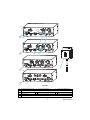
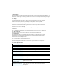
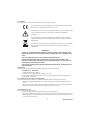
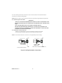
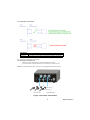
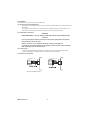
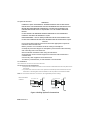
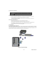
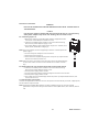
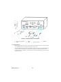
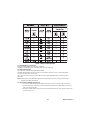
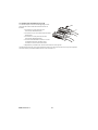
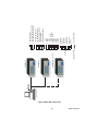
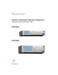
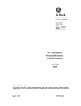
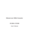
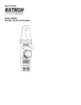
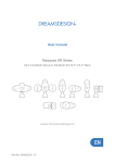
GE
Measurement & Control
Pressure Automated Calibration Equipment
Safety Instructions and User Guide - K0467
PACE Pressure Indicators
K0467 Issue No. 4
1
2
CONSULT HANDBOOK
ANALOGUE 1
22V to 26V
A
4
1
3
CONSULT HANDBOOK
ANALOGUE 1
22V to 26V
B
5
6
CONSULT HANDBOOK
XXXX
22V to 26V
XXXX
XX
7
C
CONSULT HANDBOOK
ANALOGUE 1
15
VFC 1
22V to 26V
D
Figure 1
A
D
1
4
7
Single port instrument B Two port instrument
C Three port instrument
Remote sensor instrument
Power supply connector 2 Electrical rating
3 Pressure port
Pressure port
5 Maximum working pressure 6 Pressure full-scale (range)
Power supply adaptor (see packaging list)
2
K0467 Issue No. 4
1 Introduction
The PACE Pressure Indicator measures both pneumatic and hydraulic pressures and displays, on
a colour touch-screen, the measured pressure and instrument status. The touch-screen enables
selections and settings in measuring modes. The instrument can be operated remotely through
communication interfaces.
1.1 Safety
The manufacturer has designed this equipment to be safe when operated using the
procedures detailed in this manual. Do not use this equipment for any other purpose
than that stated, the protection provided by the equipment may be impaired.
This publication contains operating and safety instructions that must be followed to
make sure of safe operation and to maintain the equipment in a safe condition. The
safety instructions are either warnings or cautions issued to protect the user and the
equipment from injury or damage.
Use qualified * technicians and good engineering practice for all procedures in this
publication.
1.2 Pressure
Do not apply pressures greater than the maximum working pressure to the equipment.
1.3 Toxic Materials
There are no known toxic materials used in construction of this equipment.
1.4 Maintenance
The equipment must be maintained using the procedures in this publication. Further
manufacturer’s procedures should be done by an authorized service agents or the
manufacturer’s service departments.
1.5 Technical advice
For technical advice contact the manufacturer.
* A qualified technician must have the necessary technical knowledge, documentation,
special test equipment and tools to carry out the required work on this equipment.
1.6 General Specification
Display
LCD: Colour display with touch-screen
Operating temperature
10°C to 50°C (50° to 122°F)
Storage temperature
-20°C to 70°C (-4° to 158°F)
Ingress protection
IP20 (EN60529)
Operating humidity
5% to 95% RH (non-condensing)
Vibration
MIL-PRF-28800 Type 2 class 5 style E/F
Operating altitude
Maximum 2000 metres (6560ft)
EMC
EN 61326
Electrical safety
EN 61010-1, UL61010-1, CSA 22.2, No. 61010-1 and IEC61010-1
Power adaptor
Input range: 100 - 240VAC, 50 to 60Hz, 700mA. Installation category
II
Pressure safety
Pressure Equipment Directive - class: sound engineering practice
(SEP) for group 2 fluids.
Pollution degree
2
Operating Environment
Indoor use only. Not rated for use in potential explosive
atmospheres
K0467 Issue No. 4
3
1.7 Symbols
The equipment contains the following symbols to identify hazards.
This equipment meets the requirements of all relevant European safety
directives. The equipment carries the CE mark.
This symbol, on the instrument, indicates that the user should refer to the
user manual. This symbol, in this manual, indicates a hazardous
operation.
Ce symbole, sur l’instrument, indique que l’utilisateur doit consulter le
manuel d’utilisation. Ce symbole, dans le manuel, indique une situation
dangereuse.
This symbol, on the instrument, indicates do not throw-away in domestic
bin, hazardous material, dispose correctly in accordance with local
regulations.
WARNINGS
TURN OFF THE SOURCE PRESSURE(S) AND CAREFULLY VENT THE PRESSURE LINES
BEFORE DISCONNECTING OR CONNECTING THE PRESSURE LINES. PROCEED WITH
CARE.
ONLY USE EQUIPMENT WITH THE CORRECT PRESSURE RATING.
BEFORE APPLYING PRESSURE, EXAMINE ALL FITTINGS AND EQUIPMENT FOR
DAMAGE. REPLACE ALL DAMAGED FITTINGS AND EQUIPMENT. DO NOT USE ANY
DAMAGED FITTINGS AND EQUIPMENT.
ISOLATE THE POWER SUPPLY BEFORE MAKING ANY ELECTRICAL CONNECTIONS TO
THE REAR PANEL.
2 Packaging
Check the contents of the PACE1000 packaging with the list that follows:
Packaging List - PACE1000
i) PACE1000 Pressure Indicator.
ii) Adaptor, power supply (GE part number 191-370).
iii) User guide and safety instructions, and CD containing the full documentation suite.
iv) Calibration certificate.
2.1 Packaging for Storage or Transportation
To store or return the instrument for calibration/repair do the procedures that follow:
1. Pack the instrument (Ref: K0470, User manual, Reference and Specification, Section
6.13).
2. Return the instrument for calibration/repair complete the return goods procedure (Ref:
K0470, User manual, Reference and Specification, Section 6.12).
3 Preparation for Use
The instrument can be used as a:
• Free-standing instrument positioned on a horizontal surface
• Panel-mounted using the panel-mount option kit (Ref: K0470, User manual, Section 2.5)
• Rack-mounted in a standard 19 inch rack using the rack-mount option kit (Ref: K0470,
User manual, Section 2.5).
4
K0467 Issue No. 4
For free-standing instruments, the feet on the front of the base can be used elevate the
instrument to a better viewing angle.
Note: Allow a free flow of air around the instrument, especially at high ambient temperatures.
3.1 Connecting the Instrument
WARNINGS
TURN OFF THE SOURCE PRESSURE(S) AND CAREFULLY VENT THE PRESSURE LINES
BEFORE DISCONNECTING OR CONNECTING THE PRESSURE LINES. PROCEED WITH
CARE.
ONLY USE EQUIPMENT WITH THE CORRECT PRESSURE RATING.
BEFORE APPLYING PRESSURE, EXAMINE ALL FITTINGS AND EQUIPMENT FOR
DAMAGE. REPLACE ALL DAMAGED FITTINGS AND EQUIPMENT. DO NOT USE ANY
DAMAGED FITTINGS AND EQUIPMENT.
3.2 Pneumatic Pressure (Figure 2)
1. Refer to the Data sheet for the correct pressure mediums to be used.
2. Connect the Unit Under Test (UUT) to the required connection port.
Note: For instruments with NPT connections, use applicable pressure sealing.
recommended method
alternative method below 100 bar
Figure 2 Sealing Pneumatic Connections
K0467 Issue No. 4
5
3.3 Pneumatic connections
Connection
Input
Reference
ISO228/1 G 1/8 parallel threads (DIN ISO228/1, JIS B0202)
ISO228/1 G 1/8 parallel threads (DIN ISO228/1, JIS B0202)
For examples of adaptors (see Page 8).
3.4 Input Pressure (Figure 3)
1. Make sure the user systems can be isolated and vented.
2. Connect the Unit Under Test (UUT) to the output connection port.
Note: For instruments with NPT connections, use applicable pressure sealing.
2
1
1) Connector
2) Bonded seal
Figure 3 Pneumatic Connections
6
K0467 Issue No. 4
4 Installation
The instrument connects to the Unit Under Test.
4.1 Input Pressure and Equipment
The pressure should not exceed 1.25 x full-scale or MWP stated on the rear panel of the
instrument.
To protect the instrument from over-pressure a suitable protection device (such as a
relief valve or bursting disc) must be fitted to prevent over pressurization.
4.2 Pneumatic Connection
WARNING
PRESSURE RANGES > 210 bar (3000 psi) ARE ONLY RATED FOR HYDRAULIC USE.
Cautions
Do not exceed the maximum pressures stated in the appropriate Component
Manual for the unit under test.
Reduce pressure at a controlled rate when venting to atmosphere.
Carefully de-pressurize all pipes to atmospheric pressure before disconnecting
and connecting to the unit under test.
4.3 Connections
1. Switch off the power supply before connecting or disconnecting the instrument.
2. Use the appropriate sealing method for all pressure connections.
4.4 Method of connection
Recommended method
K0467 Issue No. 4
7
4.5 Adaptors
Refer to the Data sheet for the range of adaptors.
8
K0467 Issue No. 4
4.6 Hydraulic Pressure
WARNINGS
HYDRAULIC LIQUID IS DANGEROUS. OBSERVE RELEVANT HEALTH AND SAFETY
PRECAUTIONS. USE APPROPRIATE PROTECTIVE BARRIERS AND EYE PROTECTION.
BEFORE APPLYING PRESSURE, EXAMINE ALL FITTINGS AND EQUIPMENT FOR
DAMAGE AND ENSURE THAT ALL EQUIPMENT IS TO THE CORRECT PRESSURE
RATING.
DO NOT EXCEED THE MAXIMUM WORKING PRESSURE OF THE INSTRUMENT.
PURGE ALL AIR FROM THE HYDRAULIC LIQUID.
PRESSURE RANGES > 210 bar (3000 psi) ARE ONLY RATED FOR HYDRAULIC USE.
DO NOT USE A SENSOR FOR GAS THAT HAS BEEN USED WITH HYDRAULIC LIQUID.
Cautions
Do not exceed the maximum pressures stated in the appropriate component
manual for the unit under test.
Reduce pressure at a controlled rate when venting to atmosphere.
Carefully de-pressurize all pipes to atmospheric pressure before disconnecting
and connecting to the unit under test.
Observe absolute cleanliness when using the instrument.
Severe damage can be caused if equipment connected to this instrument is
contaminated.
Connect only clean equipment to the instrument.
To avoid any contamination, an external filter is recommended.
4.7 Installation
The instrument connects to the Unit Under Test.
4.8 Input Pressure and Equipment
1. The pressure should not exceed 1.25 x full-scale or MWP stated on the rear panel of the
instrument.
2. To protect the instrument from over-pressure a suitable protection device (such as a
relief valve or bursting disc) must be fitted to limit the pressure to below the MWP.
Note: For instruments with NPT connections, use applicable pressure sealing.
Recommended
method
Figure 4 Sealing Hydraulic Connections
K0467 Issue No. 4
9
4.9 Hydraulic connections
Connection
Input
Reference
ISO228/1 G 1/8 parallel threads (DIN ISO228/1, JIS B0202)
ISO228/1 G 1/8 parallel threads (DIN ISO228/1, JIS B0202)
Note: Pressure connections greater than 210 bar are 9/16” 18UNF Male Autoclave.
1. Switch off the power supply before connecting or disconnecting the instrument.
2. Use the applicable sealing method for all pressure connections.
3. Isolate the hydraulic pressures and de-pressurise the pipes before connecting or
disconnecting the instrument.
4.10 Pressure input (Figure 2)
1. Make sure the user systems can be isolated and vented.
2. Use the applicable sealing method for all pressure connections.
3. The hydraulic liquid must be clean, refer to specification given in the data sheet.
4. Connect the Unit Under Test (UUT) to the appropriate connection port.
5. Fill and bleed the UUT and connecting pipes.
5 Mounting kits
5.1 Rack-mount option (Figure 5)
There must be enough space at the rear of the instrument for all the cables and pipes. The length
of the cables and pipes must allow for the removal and installation of the instrument. The cooling
air of the instrument must not be obstructed. Allow a free flow of air through the equipment rack
and around the instrument, especially at high ambient temperatures.
Figure 5 Rack-mounting
10
K0467 Issue No. 4
Procedure
1. Locate instrument in rack mount assembly (1).
2. Secure with the four M3 x 6 screws (2) (maximum length M3 x 8).
3. Support the instrument and connect the cables and pipes.
4. Refer to the electrical connections below before fitting the instrument into the
equipment rack.
5. Temporarily locate the two spigots * to each side of the equipment rack.
6. Locate and slide the instrument into the rack.
7. Locate the instrument on the spigots*.
8. Secure the instrument in the equipment rack with two of the screws and washers
(supplied).
9. Remove the two spigots* and replace with the remaining two screws and washers
(supplied).
5.2 Panel-mount option (Figure 6)
There must be enough space at the rear of the instrument for all the cables and pipes.
The length of the cables and pipes must allow for the removal and fitment of the instrument.
The cooling air of the instrument must not be obstructed.
Allow a free flow of air through the equipment rack and around the instrument, especially at high
ambient temperatures.
Figure 6 Panel-mounting
Procedure
1. Remove the four screws (1) from the instrument.
2. Locate the instrument in panel mount assembly.
3. Secure with the four screws (1).
4. Support the instrument and connect the cables and pipes.
5. Refer to the electrical connections below before fitting the instrument into the panel.
6. Secure the instrument in the panel with four screws and washers (2).
K0467 Issue No. 4
11
6 Electrical connections
WARNING
ISOLATE THE POWER SUPPLY BEFORE MAKING ANY ELECTRICAL CONNECTIONS TO
THE REAR PANEL.
Caution
Use the power adaptor supplied with the instrument (GE part no. 191-370). Using
other power adaptors may cause over-heating, this can result in a fire.
6.1 Connecting (Figure 7)
1. Before use, make sure the SELV power adaptor supplied with the
instrument is used (GE part number 191-370).
2. Install an accessible power isolator to use as the disconnecting
device in the power adaptor supply circuit.
3. The power adaptor input power supply range: 100 - 240VAC, 50 to
60Hz 700mA, Installation Category II.
Note: The power adaptor must be supplied by a fused or overload-protected
power supply.
4. Connect the power adaptor to the instrument.
5. Switch the power supply on.
6. Check that the front panel display shows the power-up sequence (Ref:
K0470, User manual, section 3.2).
Note:. After the power-up sequence, the instrument shows the default display
on the touch screen. The touch screen divides into a number of mimic
keys.
6.2 Requirements for rack-mounted and panel-mounted instruments
1. Install an accessible power isolator to use as the disconnecting
device in the power adaptor supply circuit.
2. Set the power supply isolator to OFF.
3. Connect the power adaptor before sliding the instrument into the rack.
4. Set the power supply isolator to ON.
5. Check that the front panel display shows the power-up sequence (Ref: K0470, User
manual, section 3.2).
7 Communication Connections
Connect the applicable connectors into the rear panel communications ports and, if appropriate,
secure with the captive screws.
Note: The RS232 and IEEE 488 interfaces are both enabled at power-up. Set the required
parameters in Supervisor Setup/communications menu, ((Ref: K0470, User manual, section
3.6).
12
K0467 Issue No. 4
Figure 7 Communication Connectors
1
5
Power supply adaptor
USB B
2
6
RS232
USB A
4
7
IEEE488
Ethernet (option)
7.1 RS232 Interface
When using the RS232 interface, a cable must be connected directly from the instrument
to a suitable port on the computer in a ‘point to point’ link.
The pin connections for the 9-pin D-type, RS232 connector and the relationship between
the instrument and the RS232 control signals, together with device interconnection
interface is shown in Table 2-1. The instrument is configured as Data Circuit Terminating
Equipment (DCE).
K0467 Issue No. 4
13
Table 1 RS232 Connections
7.2 Handshaking connections
Software handshaking use: TXD, RXD and GND.
Hardware handshaking use: TXD, RXD, GND, CTS, RTS and DTR.
7.3 IEEE 488 Interface
The interface complies with IEEE 488 standard.
The IEEE 488 parallel interface connects a computer/controller to one or more PACE1000
instruments and other instruments.
Up to 30 instruments can be connected through a high-speed data bus to the computer/
controller.
Note: The length of each IEEE 488 cable must be less than 3 metres to comply with the EMC
requirements (Ref: Data sheet).
7.4 Single Unit Installation (Figure 8)
1. Connect an IEEE 488 connector/cable assembly to the rear panel of the instrument.
2. Connect the other end of the connector/cable assembly to the IEEE 488 connector on
the controller/computer.
3. Change the IEEE 488 communication parameters (Ref: K0470, User manual, Supervisor
set-up, section 6.7).
14
K0467 Issue No. 4
7.5 Multiple Unit Installation (Figure 8)
To install multiple units use stacking plugs to link
1
the first instrument and second instrument as
follows::
2
1. Connector to rear panel of first
instrument (Ref Illustration).
2. Connector from controller/computer (Ref
Illustration).
3
3. Connector to rear panel of second
instrument (Ref Illustration).
4. Connect the IEEE 488 connector on the
controller/computer and the other
connector into the next instrument.
5. Repeat this procedure for all the instruments in the system.
Use the Supervisor set-up (communications) menu on each instrument to set-up the required
communication parameters (Ref: K0470, User manual 6.7).
K0467 Issue No. 4
15
Figure 8 IEEE 488 Connection
16
K0467 Issue No. 4
controller/computer
CHASSIS/FRAME
0V (GND)
ADDRESS N (30 maximum)
ADDRESS 2
ADDRESS 1
12 CHASSIS/FRAME
18 GND (6)
19 GND (7)
20 GND (8)
21 GND (9)
22 GND (10)
23 GND (11)
24 GND
DIO1
DIO2
DIO3
DIO4
DIO5
DIO6
DIO7
DIO8
1
2
3
4
13
14
15
16
DATA/
STATUS
BAR
EOI (END OR IDENTIFY)
IFC (INTERFACE CLEAR)
SRQ (SERVICE REQUEST)
ATN (ATTENTION)
REN (REMOTE ENABLE)
5
9
10
11
17
6 DAV (DATA VALID)
7 NRFD (NOT READY FOR DATA)
8 NDAC (NO DATA ACCEPTED)
8 Return Goods/Material Procedure
If the unit requires calibration or is unserviceable return it to the nearest GE Service Centre listed
at: www.ge-mcs.com.
Contact the Service Department to obtain a Return Authorisation (Worldwide excluding USA).
In the USA obtain a Return Material Authorization [RMA],
Providing the following information on either a RGA or RMA:
• Product (i.e. PACE1000)
• Serial number
• Details of defect/work to be undertaken
• Calibration traceability requirements
• Operating conditions
Safety Precautions
You must inform GE if the product has been in contact with any hazardous or toxic
substance.
The relevant COSHH or in the USA, MSDS, references and precautions to be taken
when handling.
Important notice
Service or calibration by unauthorized sources will affect the warranty and may not
guarantee further performance.
9 Approved Service Agents
For the list of service centres: www.ge-mcs.com.
K0467 Issue No. 4
17
Trademarks
All product names are trademarks of their respective company.
© The General Electric Company all rights reserved.
18
K0467 Issue No. 4