1
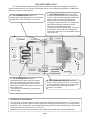
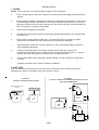
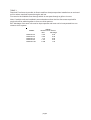
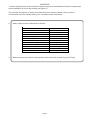
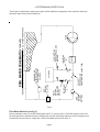
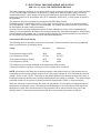
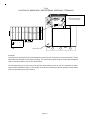
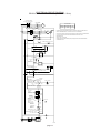
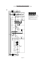
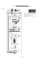
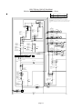
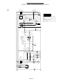
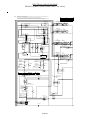
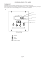
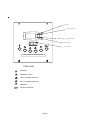
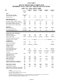
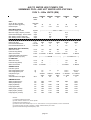
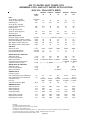
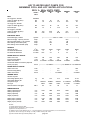
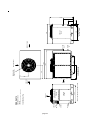
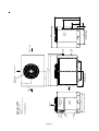
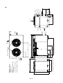
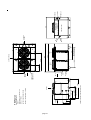
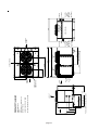
Owner Installation Manual for
PROPAC 30/45/70/90/140 M/MY
AIR/WATER HEAT PUMPS
(SD566252 ISSUE 28)
18/03/11
CONTENTS
AIR/WATER HEAT PUMPS ........................................................................................................................... 2
THE HEAT PUMP CYCLE ............................................................................................................................. 3
INSTALLATION ............................................................................................................................................ 4
1. SITING ..................................................................................................................................................... 4
2. AIR FLOW ................................................................................................................................................ 4
3. PLUMBING ............................................................................................................................................... 6
4. DETERMINING WATER FLOW ................................................................................................................. 8
5.0 ELECTROLYTIC CORROSION IN SWIMMING POOLS ......................................................................... 9
5.1 ELECTRICAL (MACHINE WIRING AND SUPPLY) .................................................................................. 10
ELECTRICAL CIRCUIT DIAGRAMS ............................................................................................................. 13
REGULAR PLANNED MAINTENANCE ......................................................................................................... 24
CONTROLS AND INDICATION LAMPS ....................................................................................................... 25
THERMOSTAT .............................................................................................................................................. 25
HEAT PUMP MALFUNCTION ....................................................................................................................... 27
DATA SHEETS .............................................................................................................................................. 30
INSTALLATION DRAWINGS ........................................................................................................................ 34
WINTERISATION PROCEDURE ................................................................................................................... 43
START UP PROCEDURE AFTER WINTERISATION..................................................................................... 43
WARRANTY CONDITIONS ........................................................................................................................... 44
MACHINE RECORD LOG ............................................................................................................................. 45
page 1
AIR/WATER HEAT PUMPS
MODELS PROPAC 30/45/70/90/140
The Calorex Propac range of air/water heat pumps for swimming pool applications consist of 5 models.
Heat pumps on this manual are designed for heating pool water and spas within the range 7ºC to 40ºC
with high water flow rate. The titanium water heat exchanger is suitable for fresh and salt water pools.
Units with the suffix M are suitable for outdoor pools operating in ambient temperatures above 10ºC, units
with the suffix MY are suitable for outdoor pools operating in ambients -15ºC to 40ºC.
The units are fully packaged and should be sited outside in a well ventilated area.
Other features include integral safety devices to protect the heat pump from internal and external faults.
Indicator lamps indicate operating mode. An adjustable thermostat controls water temperature. Also a 6
minute timer is incorporated. A 12 hour delay timer is incorporated into all machines, which after a power
interruption or from initial start will prevent the machine compressor(s) from starting for a 12 hour period.
This feature is to protect the compressors from liquid pumping which can cause internal compressor
damage.
IMPORTANT NOTE
Calorex Heat Pumps Limited is an ISO9001:2000 certified company.
All Calorex heat pumps are CE approved.
page 2
THE HEAT PUMP CYCLE
The Calorex Swimming pool heat pump provides thermodynamic heating by means of a
vapour compression cycle, (similar to that employed in a conventional refrigerator), in addition to
acting as an active solar collector.
1. THE EVAPORATOR collects the heat
from the outside ambient air, pre-heated by
the sun. In the Calorex swimming pool heat
pumps, high volumes of outside air are
drawn into the unit by the fan expelled
through the evaporator fins. The evaporator
has liquid refrigerant passing through it
Which is at a considerably lower
temperature than the ambient air. Therefore
the air gives up its heat to the refrigerant
which then vaporizes.This preheated vapour
now travels to -
2. THE COMPRESSOR where it is
compressed and upgraded to a much higher
temperature. The hot vapour now enters -
COMPRESSOR
ESSOR
2
HOT GAS
WATER OUT
3
COOL GAS
1
HEAT
EXCHANGER
AMBIENT
AIR
EVAPORATOR
WATER IN
CONDENSED
REFRIGERANT
4
COLD LIQUID
REFRIGERANT
EXPANSION
VALVE
HIGH PRESSURE SIDE
LOW PRESSURE SIDE
3. THE CONDENSER where it is
surrounded by the pool water. the heat is
given up to the cooler pool water and the
now cold refrigerant returns to its former
liquid state but still under high pressure from
the compressor.
This pressure is released by passing the
liquid through -
4. THE EXPANSION DEVICE and from
there, now at normal pressure, it is returned
to the evaporator and the cycle starts again.
Note that during the cooling cycle this
process is reversed.
Coefficient of Performance
The efficiency of a Heat Pump is usually called its ‘Coefficient of Performance’ - (C.O.P.) which
is simply a ratio of heat output to energy input, both being expressed in kW. Thus a Heat Pump
absorbing 1 kW of electricity, collecting 4 kW of energy from the air, and delivering 5 kW of heat
to the pool water is said to have a C.O.P. of 5:1.
Naturally, this ratio will vary according to the temperature of the water and the ambient air.
page 3
INSTALLATION
1. SITING
NOTE: These units are not recommended for plant room installation.
a
Ensure heat pump on site is as ordered, i.e. model, electrical supply and factory fitted
options.
b
Inspect unit for damage, in particular inspect the evaporator (finned side) to ensure that
it is undamaged. (Minor indentations in the fins do not affect performance). If severely
damaged, endorse delivery note in presence of the driver and send a recorded delivery
letter to transport company giving details.
c
Protect unit if installation is delayed.
d
Provide a firm level base capable of supporting operational weight of unit; spread load
on timber floor.
e
Ensure water cannot collect under unit - recommend units are installed on plinth
100mm above finished floor level and also to aid condensate drainage.
f
Allow adequate clearance to service panels on unit; recommend 500mm minimum
(see installation drawings).
g
All Calorex heat pumps are by design as quiet as is practical, however due
consideration should be given to siting in order to fully exploit this feature, i.e. ensure
that the inlet and outlet grilles face away from occupied premises.
h
Ensure loose debris such as leaves, grass cuttings, etc will not block air inlet filters
or grilles.
i
Consider protection from extreme weather conditions.
2. AIR FLOW
Due consideration must be given to air flow, ie do not obstruct inlet or outlet and ensure
discharge air cannot recirculate to inlet (see figures 1 and 2)
FIGURE 2
TYPICAL INSIDE OR PLANTROOM INSTALLATION
(NOT RECOMMENDED)
FIGURE 1
TYPICAL OUTSIDE INSTALLATION
ADEQUATE
DUCTING
>3m
<3m
CANOPY OR OBSTRUCTION
TOO CLOSE
PROPAC
30/45/70
ADEQUATE
DUCTING
PROPAC
90/140
page 4
TABLE 1
Required Free Areas to provide air flow to and from heat pumps when installed on an enclosed
area or where required to pass through a wall etc.
Free area is the available area through which air can pass through a grille or louvres.
Note: If multiple units are installed in an enclosed area then the inlet free areas required for
each unit can be added together to form one inlet aperture.
BUT discharge from each unit must be kept separate and must not be incorporated into one
common duct system.
MODEL
PROPAC 30
PROPAC 45
PROPAC 70
PROPAC 90
PROPAC 140
TABLE 1
Minimum Free Area m²
Inlet
Discharge
0.59
0.25
0.98
0.42
1.19
0.52
1.731
0.84
2.138
1.04
page 5
3. PLUMBING
The Calorex Pool Heat Pump must be connected after the filter in the return pipe to the
pool. If an existing heater is being retained, then the Calorex should be connected
between the filter and the other heater. (See Figures 3 & 4).
a
Calorex Heat Pumps have water inlet/outlet connections as follows:
MODEL
PROPAC 45
PROPAC 70
PROPAC 90
PROPAC 140
Water in/out
connection size
1½ BSPM
1½ BSPM
1½ BSPM
2" BSPM
MODEL
Water in/out
connection size
PROPAC PPT30
1½ BSPM
PROPAC PPT45
2" BSPM
PROPAC PPT70
2" BSPM
PROPAC PPT90
3" BSPM
PROPAC PPT140
3" BSPM
b
Suitable breakable couplings should be installed local to heat pump.
c
If heat pump installed at lower level than pool water then isolation valves should be
fitted.
d
Drain valve or plug should be fitted to lower pipe to facilitate drain down in winter period.
e
The condensation from the evaporator fins drains away through holes in the base of the
unit. If desired, an optional factory fitted driptray with 1½” sink fitting can be fitted to allow the
condensate to drain via 1½” domestic waste piping. In this case it is necessary to ensure that
the Calorex Heat Pump is placed on a level plinth so that the condensate can run away with
adequate fall to waste ie ½” per foot minimum. A U trap should also be incorporated into the
pipework.
f
When the pipework installation is complete the pool pump should be switched on and
the system tested for leaks. Also check the filter gauge to see that there is not an
excessive increase in back pressure. If everything is then working normally the water
circulating system is ready to use.
CORRECT DRAINAGE
FOR CONDENSATE
ADEQUATE FALL
'U' TRAPSUPPLIED BY
CONTRACTOR
g
Water circuit to and from unit to be capable of maintaining within specified limits the rate
of flow required by heat pump (see data sheet).
h
All pipework must be adequately supported with allowance for expansion/contraction
especially with plastic pipework.
i
It is recommended that when installing water system the last connections to be made in
the system should be the breakable couplings to avoid any stresses on to the unit
connections.
page 6
IMPORTANT
1. All pool purifying devices and chemical injection systems to be fitted down stream of heat pumps
unless installation is as per filter dosing (see figure 3).
This includes the practice of dosing chemicals direct into skimmer basket, which results in
concentrated corrosive liquids passing over vulnerable metal components.
2.
Water quality must be maintained as follows:
pH
Total Alkalinity
7.2 - 7.8
80 - 120 ppm as CaCO3
Total Hardness
150 - 250 ppm as CaCO3
Total dissolved solids
Saline Water (Titanium Condenser)
Saline Water (Cupro Nickel Condenser)
Chlorine - free Cl Range
3.
1000 Max ppm
35,000 Max ppm
8,000 Max ppm
1.0 - 2.0 ppm Domestic
Chlorine - free Cl Range
Ozone
3.0 - 6.0 ppm Commercial
0.9 Max ppm
Bromine
Baquacil
Aquamatic Ionic Purifier
2 - 5 ppm
25 - 50 ppm
Max 2 ppm Copper
Maximum pressure of water in heat pump circuit should not exceed 3 kg/cm² (50 psi).
page 7
4. DETERMINING WATER FLOW
VALVE C
BYPASS VALVE
(LOCKING GATE VALVE TYPE)
NON
RETURN
VALVE
OR LOOP
ISOLATING
VALVE
A
FILTER
PUMP
ISOLATING
VALVE
B
FLOW SETTING
PRESSURE GAUGES
METHOD
FLOW
SETTING
FLOW METER
METHOD
CALOREX
AUX
HEATER
IF FITTED
SANITISER OR
CHEMICAL DOSING
POSITION AFTER
CALOREX
POOL
POOL WATER SCHEMATIC (STANDARD)
ENSURE POOL FILTRATION PUMP SELECTION ALLOWS FOR ALL SYSTEM RESISTANCE
The Propac is fitted with a water flow switch which inhibits the operation of the machine when the
minimum water flow is below 5000 l/hr.
Fig 3
Flow Meter Method (see fig 3.)
Ensure isolation valves ‘A’ and ‘B’ and bypass valve ‘C’ are fully open. Close the bypass valve until
the flow light that is positioned on the heat pump console illuminates and then close it slightly more
to allow for flow loss due to a dirty filter. Remove handle and lock off valve ‘C’.
page 8
5.0 ELECTROLYTIC CORROSION IN SWIMMING POOLS
Electrolytic corrosion will occur when dissimilar metals that are in contact with each other create a
potential difference between themselves. Sometimes separated by a conductive substance known
as an electrolyte, the dissimilar metals will create a small voltage (potential difference) that allows
the ions of one material to pass to the other.
Just like a battery, ions will pass from the most positive material to the more negative material.
Anything more than 0.3 volts can cause the most positive material to degrade.
A swimming pool with its associated equipment can create this effect. The pool water being an
ideal electrolyte and components of the filtration circuit, heating system, steps, lights etc providing
the dissimilar metals needed to complete the circuit.
Whilst these small voltages are rarely a safety threat, they can create premature failure through
corrosion. Not dissimilar to corrosion through oxidation, electrolytic corrosion can cause complete
failure of a metallic material in a very short period of time.
In order to prevent this type of corrosion all metallic components in contact with swimming pool
water should be bonded together using 10mm² bonding cable. This includes non-electrical items
such as metal filters, pump strainer boxes, heat exchangers, steps and handrails. It is highly
recommended that bonding be retrofitted to existing pools, which may not be protected by this
system.
page 9
5.1 ELECTRICAL (MACHINE WIRING AND SUPPLY)
SEE FIG. 4,5, and 6 FOR PREFERRED METHOD
The cable supplying electricity to a machine with a given load must increase in cross sectional area
(C.S.A.) as the length increases in order that the voltage drop within the cable does not exceed
recommended limits. Cable sizing should be calculated by an appoved electrician. All electrical
work to be carried out in accordance with I.E.E. standards, latest issue, or local codes of practice
as applicable.
The machine should be installed in accordance with EMC2004/108/EC.
Protected supply to incorporate fuses or motor type circuit breakers (Type C) to specified rating,
(see Data Sheet). H.R.C. fuses are recommended. An isolator which disconnects all poles must
be fitted within 2m and in sight of machine.†
All units must be correctly earthed/grounded. An earth leakage trip of the current operating type
(30mA) is recommended to be fitted to this heat pump and any associated equipment. When fitting
recommended earth leakage trip, to avoid nuisance tripping, the machine should be connected to
its own 30mA trip separate from any other associated equipment.
Inconsistent Electrical Supply
The following limits of operation must not be exceeded if Calorex machines are to be guaranteed
either in performance or warranty terms:
Voltage
Minimum
Maximum
Three-phase machines (EU)
360V
440V
Cycle frequency (50Hz)
47.5Hz
52.5Hz
Three phase machines (60Hz)
187V
253V
Cycle frequency (60Hz)
57.0Hz
63Hz
This voltage must be made available at the heat pump whilst running.
† Note the isolator must have a minimum of 3mm air gap when turned off.
NOTE: All machines are fitted with a phase protection relay and will not run if the phases are not
connected in correct order (phase sequence) or if the supply voltage is 15% less than the nominal
voltage. (415V for 3N~ 50Hz) . The lamp on the phase rotation relay, situated in the electric box, is
illuminated when the phases are correctly connected and the voltage is sufficient. The undervoltage
protection feature is not present in phase protection relays fitted in 220V 3~ 60Hz machines.
When the machine is started for the first time it is vital that the 12 hour delay incorporated into the
compressor is allowed to occur. This delay prevents damage to the compressor which would be
expensive to repair. After this initial start up the machine can be turned on and off by use of the
standby switch. It should be noted however that when on standby the machine is still live.
page 10
Fig. 4
LOCATION OF MAINS INPUT AND EXTERNAL INTERLOCK TERMINALS
R1
0
R2
R3
REMOVE SERVICE PANEL
(1/4 TURN FASTENERS)
1
1
2
N
L1
L2
L3
D 0
2
4 5 0
9
IS S
1
3
N
L1
4
L2
5 6789
10
11
12
13
14
15
16
17
18
1 2
L3
SOFT SMART FLOW
START CLOCK SWITCH
D209450 ISS 1
MAINS SUPPLY IN
Interlock
All units have interlock circuit incorporated in control circuit, brought out to two terminals. These
terminals are shorted out for factory testing. The interlock may be used to control the heatpump
from a remote location or a built in flow switch.
On site shorting loop is to be removed and two wires taken to pair of volt free contacts in water
pump starter/contactor/relay or flow switch so that the Heat Pump cannot operate unless water
pump is operating (see figs 5 and 6).
page 11
Fig. 5
RECOMMENDED ELECTRICAL INSTALLATION FOR CALOREX HEAT PUMP WITH SINGLE
PHASE WATER PUMP
SWITCHED FUSE ISOLATOR
WITHIN 2m OF HEAT PUMP AND
SIZED IN ACCORDANCE WITH
DATASHEET
CALOREX HEAT PUMP
THREE PHASE
SINGLE PHASE
SUPPLY TO SUIT
CAPACITY OF WATER
PUMP
1
5
2
3
4
N
L1 L2 L3
6
7
8
9
10 11
N
INTERLOCK
L
L
L
N
4 POLE N/O STARTER WITH
OVERLOAD AND 230V 50Hz COIL
RATED TO SUIT WATER PUMP
N
L
N
L
N
WATER PUMP MORE THAN
¾ HP SINGLE PHASE
Fig. 6
RECOMMENDED ELECTRICAL INSTALLATION FOR CALOREX HEAT PUMP
WITH THREE PHASE WATER PUMP
SWITCHED FUSE ISOLATOR WITHIN
2m OF HEAT PUMP AND SIZED IN
ACCORDANCE WITH DATA SHEET
THREE PHASE
SUPPLY TO SUIT
CAPACITY OF
WATER PUMP
L2
1
2
3
4
5
N
L1
L2
L3
6
7
8
9
10
11
L3
INTERLOCK
L3
CALOREX
HEAT PUMP
THREE PHASE
L3
L2
L
L1
4 POLE N/O STARTER WITH
OVERLOAD AND 230v 50Hz COIL
RATED TO SUIT WATER PUMP
N
L1
L2
WATER PUMP
THREE PHASE
L3
page 12
ELECTRICAL CIRCUIT DIAGRAMS
ELECTRICAL CIRCUIT DIAGRAM
PROPAC 30BM THREE PHASE (400V 3 N~ 50Hz)
FAN CIRCUIT BREAKER
5
6 (N/C)
CONTACTOR
5
6 (N/O)
3
4 (N/C)
3
4 (N/O)
1
2 (N/C)
1
2 (N/O)
A1
FAN
A2
COMP CIRCUIT BREAKER
TRIP / OFF = BREAK CONTACT
CONTACTOR
5
5
6 (N/C)
6 (N/O)
MCB SETTINGS
(W1)
3
4 (N/C)
3
4 (N/O)
(V1)
1
2 (N/C)
1
2 (N/O)
(U1)
COMP
HEATER
TRIP / OFF = BREAK CONTACT
DELAY TIMER 2
A1
A2
21
22
COMP AUX
(NC)
11 (N/O)
A2
RELAY (R2)
14
A1
(COM)
DELAY TIMER 1
12 HOUR
(COM) 15
A1
(N/O)
H
DEFROST
STAT
(BREAKS TO
'H' ON TEMP
FALLING)
C
(COM)
A2
DEFROST
LIGHT
8
9
SENSOR
(N/C)
L
18 (N/O)
SMART CLOCK
FEED TERMINALS
(N/O)
(N/C)
OUT 4
1
6
5
10 11
DIG STAT 1 STAGE
MAKES 6 TO 4 ON TEMP FALLING
2 (N)
1 (L)
(COM)
(N/O)
(STANDBY) 3
STANDBY
SWITCH
(N/C)
2 (RUN)
1 (COM)
FLOW OK LIGHT
(N/O)
RELAY
(R1)
(COM)
4
B
7
A
WATER
FLOW
SWITCH
(N/O)
SOFT START
THERMAL
O/LOAD &
FAULT LIGHT
IF FITTED
INTERLOCK
TERMINALS
STARTER OR
EXTERNAL
FLOW SWITCH
(N/C) L
LP SWITCH
(BREAKS TO H ON
PRESSURE FALLING)
(N/O) L
HP SWITCH
(BREAKS TO L ON
PRESSURE RISING)
H (N/O)
FAULT
LIGHT
C (COM)
H (N/C)
C (COM)
TK
(N/C)
TK
FAN THERMAL CUT OUT
COMPRESSOR
MOTOR
PROTECTOR
(N/C)
96
(N/C)
95
FAN MCB AUX BLK : ALARM
TRIP = BREAK CONTACT
96
(N/C)
95
COMPRESSOR MCB
AUX BLK : ALARM
5
3
1
L3 L2 L1
6 NO
4 NO
2 NO
CONTROL
CIRCUIT BREAKER
L3
L2
L1
12 NC
TRIP = BREAK CONTACT
MAINS LIGHT
14 NO
11 COM
PHASE
ROTATION RELAY
NEUTRAL
page 13
CONTROL COMPRESSOR
2.5A
22.9A
FAN
0.8A
ELECTRICAL CIRCUIT DIAGRAM
PROPAC 45BM THREE PHASE (400V 3 N~ 50Hz)
FAN CIRCUIT BREAKER
TRIP / OFF = BREAK CONTACT
5
6 (N/C)
CONTACTOR
5
6 (N/O)
3
4 (N/C)
3
4 (N/O)
1
2 (N/C)
1
2 (N/O)
CONTROL COMPRESSOR
A2
COMP
COMP CIRCUIT BREAKER
TRIP / OFF = BREAK CONTACT
2.5A
5
6 (N/C)
CONTACTOR
5
6 (N/O)
3
4 (N/C)
3
4 (N/O)
(V1)
1
2 (N/C)
1
2 (N/O)
(U1)
(W1)
COMP
23.8A
FAN
1.7A
MCB CONTACTS / MCB ALARM CONTACTS / MCB AUX CONTACTS SHOWN WITH
CIRCUIT BREAKER MANUALLY SWITCHED TO THE ON CONDITION
HEATER
A1
MCB SETTINGS
FAN
WATER FLOW SWITCH CONTACTS SHOWN WITH WATER FLOW AT MAXIMUM RATE
DELAY TIMER 2
A1
A2
21
22
ALL OTHER CONTACTS SHOWN IN DE-ENERGISED STATE BUT WITH
REFRIGERATION
CIRCUIT FULLY CHARGED
WHERE CONTACTS ARE MARKED (N/O) OR (N/C) ON CIRCUIT DIAGRAM ABOVE
CONDITIONS APPLY
COMP AUX
(NC)
63
64
LIQUID LINE SHUT OFF VALVE
COMP AUX
(NO)
11 (N/O)
A2
RELAY (R2)
A1
14
(COM)
DELAY TIMER 1
12 HOUR
(COM)
(N/C)
L
DEFROST
STAT
(N/O)
H
15
18 (N/O)
A1
A2
DEFROST
LIGHT
C
(COM)
(BREAKS TO 'H' ON
TEMP FALLING)
8
9
SMART CLOCK
FEED TERMINALS
1
(L)
2
(N)
(N/O)
OUT
1
SENSOR
(N/C)
4
6
5
DIG STAT 1 STAGE
MAKES 6 TO 4 ON TEMP FALLING
10
11
(COM)
STANDBY
1 (COM) SWITCH
[RUN] (N/O) 2
FLOW OK LIGHT
(N/O) 4
[STANDBY] (N/C) 3
(N/O)
(COM) 7
1 (N/C)
A
WATER FLOW SWITCH
B
RELAY (R1)
SOFT START
THERMAL
O/LOAD & FAULT
LIGHT IF FITTED
INTERLOCK
TERMINALS
STARTER OR
EXTERNAL
FLOW SWITCH
LP SWITCH
(N/C) L
(BREAKS TO H ON
PRESSURE FALLING)
H (N/O)
C (COM)
(N/O) L
HP SWITCH
(BREAKS TO L ON
PRESSURE RISING)
C (COM)
FAN THERMAL
CUT OUT
TK
TK
COMPRESSOR
MOTOR
PROTECTOR
(N/C)
95
TRIP = BREAK CONTACT
96
COMPRESSOR MCB AUX BLK : ALARM
95
L1
5
3
6 (N/C)
4 (N/C)
L3
L2
1
2 (N/C)
L1
12 (N/C)
TRIP = BREAK CONTACT
L2
(N/C)
96
FAN MCB AUX BLK : ALARM
CONTROL CIRCUIT
BREAKER
TRIP / OFF BREAK CONTACT
FAULT LIGHT
H (N/C)
(N/C)
(N/C)
MAINS LIGHT
14 (N/O)
11 (COM)
PHASE
ROTATION RELAY
NEUTRAL
page 14
ELECTRICAL CIRCUIT DIAGRAM
PROPAC 45EM THREE PHASE (220V 3~ 60Hz)
TRIP / OFF = BREAK CONTACT
5
6 (N/C)
3
4 (N/C)
1
2 (N/C)
CONTACTOR
5
6 NO
3
4 NO
1
2 NO
FAN
A2
A1
MCB SETTINGS
COMP CIRCUIT BREAKER
TRIP / OFF = BREAK CONTACT
5
6 (N/C)
3
4 (N/C)
3
4 (N/O)
(V1)
1
2 (N/C)
1
2 (N/O)
(U1)
(W1)
COMP
HEATER
CONTROL COMPRESSOR
CONTACTOR
5
6 (N/O)
21
22
WATER FLOW SWITCH CONTACTS SHOWN WITH WATER
FLOW AT MAXIMUM RATE
LIQUID LINE SHUT
OFF VALVE
14
11 (N/O)
A2
RELAY (R2)
14
A1
(COM)
DELAY TIMER 1
12 HOUR
(COM) 15
18 (N/O)
A1
A2
DEFROST
LIGHT
(BREAKS TO 'H' ON
TEMP FALLING)
SENSOR
7
8
SMART CLOCK
FEED TERMINALS
(N/O)
2
(N)
1
(L)
4
OUT 1
6
(N/C)
5
DIG STAT 1 STAGE
MAKES 6 TO 4 ON TEMP FALLING
10
11
(COM)
MAINS LIGHT
STANDBY
SWITCH
[RUN] (N/O) 2
1 (COM)
FLOW OK LIGHT
(N/O) 4
[STANDBY] (N/C) 3
(N/O)
(COM) 7
WATER FLOW
SWITCH
1 (N/C)
A
B
RELAY (R1)
SOFT START
THERMAL
O/LOAD &
FAULT
LIGHT IF
FITTED
INTERLOCK
TERMINALS
STARTER
OR
EXTERNAL
FLOW
SWITCH
(N/C) L
LP SWITCH
(BREAKS TO H ON
PRESSURE FALLING)
(N/O) L
HP SWITCH
(BREAKS TO L ON
PRESSURE RISING)
FAN THERMAL
CUT OUT
H (N/O)
C (COM)
C (COM)
TK
(N/C)
COMPRESSOR
MOTOR
PROTECTOR
L3 L2 L1
(N/C)
FAN MCB AUX BLK :
ALARM
TRIP = BREAK CONTACT
96
COMPRESSOR MCB
AUX BLK : ALARM
TRIP = BREAK CONTACT
44
6 (N/C)
3
1
4 (N/C)
2 (N/C)
L3
L2
L1
95
43
12 (N/C)
5
FAULT LIGHT
H (N/C)
TK
ALL OTHER CONTACTS SHOWN IN DE-ENERGISED
STATE BUT WITH REFRIGERATION CIRCUIT FULLY
CHARGED
WHERE CONTACTS ARE MARKED (N/O) OR (N/C) ON
CIRCUIT DIAGRAM ABOVE CONDITIONS APPLY
COMP AUX
(N/O)
C
(COM)
3.3A
MCB CONTACTS / MCB ALARM CONTACTS / MCB AUX
CONTACTS SHOWN WITH CIRCUIT BREAKER MANUALLY
SWITCHED TO THE ON CONDITION
13
DEFROST
STAT
FAN
A2
COMP AUX
(N/C)
(N/O)
H
46.8A
A1
DELAY TIMER 2
(N/C)
L
2.5A
(N/C)
(N/C)
14 (N/O)
11 (COM)
CONTROL CIRCUIT
PHASE
BREAKER
ROTATION RELAY
TRIP / OFF = BREAK CONTACT
page 15
ELECTRICAL CIRCUIT DIAGRAM
PROPAC 70BM THREE PHASE (400V 3 N~ 50Hz)
CIRCUIT BREAKER
TRIP / OFF = BREAK CONTACT
5
6 (N/C)
3
4 (N/C)
1
2 (N/C)
CONTACTOR
5
6 (N/O)
3
4 (N/O)
1
2 (N/O)
A1
MCB SETTINGS
FAN
CONTROL COMPRESSOR
A2
2.5A
TRIP / OFF = BREAK CONTACT
5
6 (N/C)
CONTACTOR
5
6 (N/O)
(W1)
3
4 (N/C)
3
4 (N/O)
(V1)
1
2 (N/C)
1
2 (N/O)
(U1)
COMP
HEATER
CIRCUIT BREAKER
A1
A2
WATER FLOW SWITCH CONTACTS SHOWN WITH WATER FLOW AT MAXIMUM
RATE
21
22
ALL OTHER CONTACTS SHOWN IN DE-ENERGISED STATE BUT WITH
REFRIGERATION CIRCUIT FULLY CHARGED
COMP AUX
(NC)
13
14
WHERE CONTACTS ARE MARKED (N/O) OR (N/C) ON CIRCUIT DIAGRAM ABOVE
CONDITIONS APPLY
LIQUID LINE SHUT OFF VALVE
11 (N/O)
COMP AUX
(NO)
A2
RELAY (R2)
A1
14 (COM)
DELAY TIMER 1
12 HOUR
(COM) 15
18 (N/O)
A1
A2
DEFROST
LIGHT
C
(COM)
(BREAKS TO 'H'
ON TEMP
FALLING)
8
9
SENSOR
DEFROST
STAT
(N/O)
H
SMART CLOCK
FEED TERMINALS
(N/O)
(L)
(N)
1
2
(N/C)
4
OUT 1
6
5
DIG STAT 1 STAGE
MAKES 6 TO 4 ON TEMP FALLING
10
11
(COM)
[RUN] (N/O) 2
STANDBY
1 (COM) SWITCH
FLOW OK LIGHT
(N/O) 4
[STANDBY] (N/C) 3
(N/O)
(COM) 7
WATER FLOW
SWITCH
1 (N/C)
A
B
RELAY (R1)
SOFT
START
THERMAL
O/LOAD &
FAULT
LIGHT IF
FITTED
INTERLOCK
TERMINALS
STARTER
OR
EXTERNAL
FLOW
SWITCH
H (N/O)
(N/C) L
LP SWITCH
(BREAKS TO H ON
PRESSURE FALLING)
(N/O) L
HP SWITCH
(BREAKS TO L ON
PRESSURE RISING)
C (COM)
C (COM)
TK
TK
(N/C)
FAN MCB AUX
BLK : ALARM
TRIP = BREAK CONTACT
96
COMPRESSOR MCB
AUX BLK : ALARM
TRIP = BREAK CONTACT
44
95
43
(N/O)
(N/O)
12 (N/C)
L3
L2 L1
6 (N/O)
4 (N/O)
2 (N/O)
CONTROL
CIRCUIT BREAKER
FAULT LIGHT
H (N/C)
FAN THERMAL
CUT OUT
5
3
1
FAN
2.7A
MCB CONTACTS / MCB ALARM CONTACTS / MCB AUX CONTACTS SHOWN
WITH CIRCUIT BREAKER MANUALLY SWITCHED TO THE ON CONDITION
DELAY TIMER 2
(N/C)
L
36.8A
L3
L2
L1
MAINS LIGHT
14 (N/O)
11 (COM)
PHASE
ROTATION RELAY
NEUTRAL
page 16
ELECTRICAL CIRCUIT DIAGRAM
PROPAC 90BM THREE PHASE (400V 3 N~ 50Hz)
COMPRESSOR
1
CONTROL
2.5A
COMPRESSOR
2
23.8A
23.8A
FAN
1
FAN
2
1.7A
1.7A
MCB CONTACTS / MCB ALARM CONTACTS / MCB AUX CONTACTS SHOWN WITH CIRCUIT
BREAKER MANUALLY SWITCHED TO THE ON CONDITION
WATER FLOW SWITCH CONTACTS SHOWN WITH WATER FLOW AT MAXIMUM RATE
ALL OTHER CONTACTS SHOWN IN DE-ENERGISED STATE BUT WITH REFRIGERATION CIRCUIT
FULLY CHARGED
RELAY (R5)
(N/C) 1
WHERE CONTACTS ARE MARKED (N/O) OR (N/C) ON CIRCUIT DIAGRAM ABOVE CONDITIONS
APPLY
7 (COM)
(N/O) 4
7
(COM)
9
(COM)
(N/C) 3
DEFROST
LAMP
RELAY (R3)
(N/C) 1
(N/O) 6
A
(N/O) 4
B
9
(COM)
(N/C) 3
FAN 1
CIRCUIT BREAKER
TRIP / OFF =
BREAK CONTACT
(N/O) 6
A
FRIDGE CCT 1
DEFROST
BREAKS TO 'H'
ON
TEMPERATURE
FALLING
(N/C) L
FRIDGE CCT 2
DEFROST
BREAKS TO 'H' (N/C) L
ON
TEMPERATURE
FALLING
B
6 (N/C)
4 (N/C)
2 (N/C)
5
3
1
H (N/O)
C (COM)
A1
H (N/O)
(N/C) 1
7 (COM)
(N/C) 3
(N/C) 3
9 (COM)
(N/O) 6
9 (COM)
A1
A
(N/O) 6
A
FAN 2
CIRCUIT BREAKER
FAN 2
TRIP / OFF = BREAK CONTACT CONTACTOR
6 (N/C)
6 (N/O)
5
5
4 (N/C)
4 (N/O)
3
3
2 (N/C)
2 (N/O)
1
1
7 (COM)
(N/O) 4
B
COMP 1
CIRCUIT BREAKER
TRIP / OFF =
BREAK CONTACT
6 (N/C)
5
B
3
1
FRIDGE CCT 2
LP SWITCH
BREAKS TO 'H'
ON PRESSURE (N/C) L
FALLING
H (N/O)
C (COM)
CCT 1
FAULT
LIGHT
1
H (N/C)
C (COM)
FRIDGE CCT 2
HP SWITCH
BREAKS TO 'L' (N/O) L
ON PRESSURE
RISING
COMPRESSOR 2
MCB AUX BLK
TRIP = BREAK CONTACT
96 (N/C)
95
CCT 2
FAULT LIGHT
2
H (N/C)
96 (N/C)
95
64 (N/O) AUX
FRIDGE CCT 1
LIQUID LINE SHUT OFF
VALVE COIL
COMP 2
CONTACTOR
6 (N/O)
5
4 (N/O)
3
2 (N/O)
1
A2
21
22 (N/C) AUX
63
64 (N/O) AUX
COMPRESSOR 2
MOTOR
PROTECTOR
FAN 2 THERMAL
CUT OUT
FAN 1 THERMAL
CUT OUT
FAN 2 MCB AUX
BLK : ALARM
TRIP = BREAK CONTACT
FAN 1 MCB AUX
BLK : ALARM
TRIP = BREAK CONTACT
TK (N/C)
TK
COMPRESSOR 1 MCB
AUX BLK
FAULT
LIGHT
TRIP / OFF = BREAK
CONTACT
A2
A1
54 (N/C)
53
TK (N/C)
TK
96 (N/C)
(N/C) 1
95
(N/O) 4
96 (N/C)
95
DELAY TIMER 1
(12 HOUR)
16 (N/C)
(COM) 15
18 (N/O)
A1
14 (N/O)
L3
L2
L1
A2
(N/C) 16
COMPRESSOR 1
MOTOR
PROTECTOR
DELAY TIMER 2
(6 MINS)
11
15
(COM)
INTERLOCK
TERMINALS
7
10
54 (N/C)
53
TRIP / OFF = BREAK
CONTACT
(N/O) 18
(N/C)
7 (COM)
A
COMPRESSOR 2 MCB
AUX BLK
WATER FLOW
SWITCH
BREAKS ON
WATER FLOW
RATE FALLING
6
STARTER OR
EXTERNAL
FLOW SWITCH
(W1)
(V1) COMP
2
(U1)
DELAY TIMER 3
(7 MINS)
(N/O) 18
(N/C) 16
15 (COM)
B
RELAY (R6)
(N/O) 4
(N/C) 1
22 (N/C) AUX
63
FRIDGE CCT 2
LIQUID LINE SHUT OFF
VALVE COIL
A1
(N/O) 4
2 (N)
6 (COM)
1 (L)
SOFT START
THERMAL
O/LOAD &
FAULT LAMP IF
FITTED
CONTROL CIRCUIT
BREAKER
TRIP / OFF = BREAK CONTACT
A2
FLOW OK LIGHT
STANDBY
SWITCH
(W1)
COMP
(V1)
1
(U1)
21
SENSOR
3 (N/C) [STANDBY]
(COM) 1
6 (N/C)
4 (N/C)
2 (N/C)
6 (N/O)
4 (N/O)
2 (N/O)
5
3
1
DIGITAL STAT (1 STAGE)
[RUN] (N/O) 2
5
3
1
COMP 1
CONTACTOR
A1
8
SMART CLOCK
FEED TERMINALS
10
11
COMP 2
CIRCUIT BREAKER
TRIP / OFF =
BREAK CONTACT
6 (N/C)
5
3
4 (N/C)
2 (N/C)
1
C (COM)
(N/C) 5
MAKES 4 TO 6 ON
TEMP FALLING
A2
A1
H (N/O)
C (COM)
9
OUT 1
4 (N/C)
2 (N/C)
FAN
2
COMP 1
HEATER
(N/C) 1
COMPRESSOR 1
MCB AUX BLK
TRIP = BREAK CONTACT
A2
COMP 2
HEATER
RELAY (R4)
(N/O) 4
FRIDGE CCT 1
HP SWITCH
BREAKS TO 'L' (N/O) L
ON PRESSURE
RISING
FAN
1
C (COM)
RELAY (R2)
FRIDGE CCT 1
LP SWITCH
BREAKS TO 'H'
ON PRESSURE (N/C) L
FALLING
FAN 1
CONTACTOR
6 (N/O)
5
3
4 (N/O)
2 (N/O)
1
A2
7 (COM)
(N/C) 3
9 (COM)
(N/O) 6
A
B
RELAY (R1)
12 (N/C)
11 (COM)
PHASE
ROTATION
RELAY
MAINS LIGHT
L3 L2 L1
NEUTRAL
page 17
ELECTRICAL CIRCUIT DIAGRAM
PROPAC140BM THREE PHASE (400V 3 N~ 50Hz)
MCB SETTINGS
CONTROL
COMPRESSORS 1 & 2
2.5A
SEE FIG.1
DEFROST
LIGHT
1
4
6
1
4
7
3
6
B
SEE FIG.1
1
4
7
A
3
9
A
MCB CONTACTS / MCB ALARM CONTACTS / MCB AUX CONTACTS SHOWN
WITH CIRCUIT BREAKER MANUALLY SWITCHED TO THE ON CONDITION
FRIDGE
(N/C)
CIRCUIT 2
L
DEFROST
H(N/O)
(BREAKS TO
(COM) C
'H' ON TEMP
FALLING)
SEE FIG.1
1
4
7
3
9
6
RELAY (R3)
FRIDGE
CIRCUIT 1
(N/C)
DEFROST
L
H(N/O)
(BREAKS TO
'H' ON TEMP
C
(COM)
FALLING)
6
WATER FLOW SWITCH CONTACTS SHOWN WITH WATER FLOW AT
MAXIMUM RATE
B
RELAY (R5)
9
A
ALL OTHER CONTACTS SHOWN IN DE-ENERGISED STATE BUT WITH
REFRIGERATION CIRCUIT FULLY CHARGED
9
A
2.7A
WHERE CONTACTS ARE MARKED (N/O) OR (N/C) ON CIRCUIT DIAGRAM
ABOVE CONDITIONS APPLY
7
3
SEE FIG.1
FANS 1 & 2
36.8A
(N/C) 1
(N/O) 4
7 (COM)
(N/C) 3
(N/O) 6
9 (COM)
A
B
RELAY (R4)
B
TYP. RELAY
FIG.1
B
RELAY (R2)
H (N/O)
C (COM)
CIRCUIT 1
FAULT
LIGHT
H (N/C)
FRIDGE CIRCUIT 1 (N/O) L
COMP HP SWITCH
(BREAKS TO 'L' ON
PRESSURE RISING)
C (COM)
FRIDGE
CIRCUIT 2
(N/O) L
COMP HP
SWITCH
H (N/O)
C (COM)
CIRCUIT 2
FAULT
LIGHT
H (N/C)
FAN 1
CIRCUIT BREAKER
FAN 1
TRIP / OFF = BREAK CONTACT CONTACTOR
5
6 (N/O)
6 (N/C)
5
C (COM)
(BREAKS TO 'L' ON
PRESSURE RISING)
44
43
COMP2 MCB AUX BLK
TRIP / OFF = BREAK
CONTACT
(N/O)
44
9
8
L
N
3
4 (N/C)
3
1
2 (N/C)
1
U1
4 (N/O) V1 FAN
1
2 (N/O) W1
A2
A1
FAN 2
CIRCUIT BREAKER
FAN 2
TRIP / OFF = BREAK CONTACT CONTACTOR
6 (N/C)
5
6 (N/O)
5
(N/O)
3
4 (N/C)
3
1
2 (N/C)
1
U1
4 (N/O) V1 FAN
2
2 (N/O) W1
A2
A1
COMP 1
CIRCUIT BREAKER
COMP 1
TRIP / OFF = BREAK CONTACT CONTACTOR
SENSOR
43
COMP 1 MCB AUX BLK
TRIP / OFF = BREAK
CONTACT
FRIDGE
CIRCUIT 2
COMP LP
(N/C) L
SWITCH
(BREAKS TO 'H' ON
PRESSURE FALLING)
SMART CLOCK
FEED TERMINALS
5
6 (N/C)
5
6 (N/O) (L3)
3
4 (N/C)
3
4 (N/O)(L2)
1
2 (N/C)
1
2 (N/O)(L1)
A2
A1
(N/O)
4
1 (L)
DIG STAT
1 STAGE
2 (N) OUT 1
6
MAKES 6 TO 4 ON
TEMP FALLING
10
21
11
COMP
1
HEATER
FRIDGE CIRCUIT 1
COMP LP SWITCH (N/C) L
(BREAKS TO 'H' ON
PRESSURE
FALLING)
22
COMP 1 AUX
(NC)
(COM)
13
14
COMP 1 AUX
(NO)
VALVE,COIL
(LIQUID LINE SHUT OFF)
STANDBY
SWITCH
(N/O) (RUN)
2
CIRCUIT 1
COMP 2
CIRCUIT BREAKER
TRIP / OFF = BREAK CONTACT
1
(COM)
FLOW OK LIGHT
(N/C)
1
6 (N/C)
5
3
4 (N/C)
3
4 (N/O)(L2)
1
2 (N/C)
1
2 (N/O)(L1)
A2
A1
(N/O)
4
B
21
7
(COM)
A
WATER
FLOW
SWITCH
(N/O)
22
13
14
COMP 2 AUX
(NO)
6
SOFT START
THERMAL
O/LOAD &
FAULT LIGHT
IF FITTED
7
10
STARTER OR
EXTERNAL
FLOW SWITCH
CIRCUIT 2
TK(N/C)
TK
TK(N/C)
TK
95
(N/C)
96
95
96
VALVE,COIL
(LIQUID LINE SHUT OFF)
(N/O)
6 MINS
DELAY
TIMER (2)
11
FAN 2 THERMAL
CUT OUT
FAN 1 THERMAL
CUT OUT
FAN 2 MCB
AUX BLK : ALARM
TRIP = BREAK
CONTACT
FAN 1 MCB
AUX BLK : ALARM
TRIP = BREAK
CONTACT
COMP
2
COMP 2 AUX
(NC)
INTERLOCK
TERMINALS
RELAY
(R6)
COMP 2
CONTACTOR
6 (N/O) (L3)
5
HEATER
(STANDBY) (N/C)
3
FAULT
LIGHT
18
15
A2
A1
(COM)
COMPRESSOR 1 MCB
AUX BLK
TRIP / OFF = BREAK
34
CONTACT
(N/O)
33
(N/C)
(N/C) 1
15
A2
A1
(COM)
34
(N/O)
33
COMPRESSOR 2 MCB
AUX BLK
TRIP / OFF = BREAK
CONTACT
9 (COM)
(N/O) 6
A
18 (N/O)
A1
18
7 (COM)
(N/O) 4
(N/C) 3
DELAY TIMER 1
(12 HOUR)
16 (N/C)
(COM) 15
(N/O)
7 MINS
DELAY
TIMER (3)
B
RELAY (R1)
A2
14
(N/O)
L3 L2 L1
5
6 (N/C)
3
1
4 (N/C)
2 (N/C)
CONTROL
CIRCUIT BREAKER
L3
L2
L1
12 (N/C)
11 (COM)
MAINS LIGHT
NEUTRAL
PHASE
ROTATION
RELAY
D579450
page 18
ELECTRICAL CIRCUIT DIAGRAM
PROPAC30BMY THREE PHASE (400V 3 N~ 50Hz)
COMP
CIRCUIT BREAKER
COMPRESSOR
CONTACTOR
TRIP / OFF = BREAK CONTACT
5
6 (N/C)
5
6 (N/O)
(W1)
3
4 (N/C)
3
4 (N/O)
(V1)
1
2 (N/C)
1
2 (N/O)
(U1)
21
22 (N/C)
COMP
MCB SETTINGS
DELAY TIMER 1
(12 HOUR)
A1
(COM) 15
HEATER
COMPRESSOR
FAN
2.5A
22.9A
0.8A
A2
RELAY (R2)
18 (N/O)
16 (N/C)
A1
A2
14
11 (N/O)
(N/O)
A1
MCB CONTACTS / MCB ALARM CONTACTS / MCB AUX CONTACTS SHOWN WITH
CIRCUIT BREAKER MANUALLY SWITCHED TO THE ON CONDITION
A2
WATER FLOW SWITCH CONTACTS SHOWN WITH WATER FLOW AT MAXIMUM
RATE
DELAY TIMER 2
5 (N/C)
4 (N/O)
9
8
SMART CLOCK
FEED TERMINALS
OUT 1
10
MAKES 4 TO 6 ON TEMP
FALLING
SENSOR
ALL OTHER CONTACTS SHOWN IN DE-ENERGISED STATE BUT WITH
REFRIGERATION
CIRCUIT FULLY CHARGED
WHERE CONTACTS ARE MARKED (N/O) OR (N/C) ON CIRCUIT DIAGRAM ABOVE
CONDITIONS APPLY
2 (N)
(COM) 6
11
1 (L)
CONTROL
3 (N/C) [STANDBY]
[RUN] (N/O) 2
STANDBY
SWITCH
DIGITAL STAT (1 STAGE)
WATER FLOW OK LIGHT
(COM)
1
(N/O) 4
B
1 (N/C)
RELAY (R1)
(COM) 7
A
WATER FLOW
SWITCH
(N/O)
INTERLOCK
TERMINALS
SOFT START
THERMAL O/LOAD &
FAULT LAMP IF
FITTED
STARTER OR EXTERNAL
FLOW SWITCH
LP SWITCH
(N/C) L
(BREAKS TO 'H' ON PRESSURE FALLING)
HP SWITCH
(N/O) L
(BREAKS TO 'L' ON PRESSURE RISING)
FAN THERMAL CUT
OUT
H (N/O)
C (COM)
H (N/C)
TK
TK
COMPRESSOR MOTOR
PROTECTOR
(NC)
(N/C)
FAN MCB AUX
BLK : ALARM
96 (N/C)
TRIP = BREAK CONTACT
COMPRESSOR MCB
AUX BLK : ALARM
95
96 (N/C)
95
MAKES 1 TO 3 ON TEMP FALLING
DEFROST STAT
TRIP = BREAK CONTACT
COMP
CONTACTOR
AUX BLOCK
FAULT
LIGHT
C (COM)
LIQUID LINE
SHUT OFF VALVE
2 (N)
REVERSING VALVE
DEFROST LIGHT
3 (N/O)
4 (N/C)
63
64 (N/O)
A1
A2
5
6 (N/C)
5
6 (N/O)
3
4 (N/C)
3
4 (N/O)
1
2 (N/C)
1
2 (N/O)
(COM) 1
FAN CIRCUIT BREAKER
TRIP / OFF = BREAK CONTACT
FAN
14
(N/O)
FAN CONTACTOR
5
6 (N/C)
L3
3
4 (N/C)
L2
1
2 (N/C)
L1
CONTROL CIRCUIT
BREAKER
TRIP / OFF = BREAK CONTACT
12 (N/C)
11 (COM)
PHASE
ROTATION
RELAY
MAINS LIGHT
L3 L2 L1
NEUTRAL
page 19
ELECTRICAL CIRCUIT DIAGRAM
PROPAC 45BMY THREE PHASE (400V 3 N~ 50Hz)
COMP
CIRCUIT BREAKER
COMPRESSOR
CONTACTOR
TRIP / OFF = BREAK CONTACT
5
3
4 (N/C)
1
2 (N/C)
MCB SETTINGS
(W1)
CONTROL
COMPRESSOR
4 (N/O)
(V1)
2.5A
23.8A
1
2 (N/O)
(U1)
21
22 (N/C)
5
6 (N/C)
6 (N/O)
3
HEATER
A2
16 (N/C)
A1
A2
14
11 (N/O)
(N/O)
A1
WHERE CONTACTS ARE MARKED (N/O) OR (N/C) ON CIRCUIT DIAGRAM ABOVE
CONDITIONS APPLY
A2
DELAY TIMER 2
5 (N/C)
4 (N/O)
9
8
SMART CLOCK
FEED TERMINALS
10
MAKES 4 TO 6 ON TEMP
FALLING
OUT 1
SENSOR
1 (L)
2 (N)
(COM) 6
11
DIGITAL STAT (1 STAGE)
3 (N/C) [STANDBY]
[RUN] (N/O) 2
WATER FLOW OK LIGHT
STANDBY
SWITCH
(COM) 1
1
(N/C)
(N/O) 4
B
RELAY (R1)
(COM) 7
A
WATER FLOW
SWITCH
(N/O)
INTERLOCK
TERMINALS
SOFT START
THERMAL O/LOAD &
FAULT LAMP IF
FITTED
STARTER OR EXTERNAL
FLOW SWITCH
LP SWITCH
(BREAKS TO 'H' ON
PRESSURE FALLING)
H (N/O)
(N/C) L
C (COM)
(N/O)
L
HP SWITCH
(BREAKS TO 'L' ON
PRESSURE RISING)
H (N/C)
FAULT
LIGHT
C (COM)
FAN THERMAL
CUT OUT
TK
(NC)
TK
COMPRESSOR MOTOR
PROTECTOR
(N/C)
FAN MCB AUX BLK :
ALARM
TRIP = BREAK
CONTACT
96
(N/C)
95
96
(N/C)
COMPRESSOR MCB AUX
BLK : ALARM
TRIP = BREAK
CONTACT
95
2
(N)
MAKES 1 TO 3 ON
TEMP FALLING
DEFROST STAT
LIQUID LINE SHUT OFF VALVE
REVERSING VALVE
DEFROST LIGHT
3 (N/O)
COMP
CONTACTOR
AUX BLOCK
4 (N/C)
A1
A2
6 (N/C)
5
6 (N/O)
4 (N/C)
3
4 (N/O)
2 (N/C)
1
2 (N/O)
63
64 (N/O)
5
3
1
(COM) 1
FAN CIRCUIT BREAKER
TRIP / OFF = BREAK CONTACT
FAN
14 (N/O)
FAN CONTACTOR
5
6 (N/C)
L3
3
4 (N/C)
L2
1
2 (N/C)
L1
CONTROL CIRCUIT
BREAKER
TRIP / OFF = BREAK
CONTACT
L3 L2 L1
WATER FLOW SWITCH CONTACTS SHOWN WITH WATER FLOW AT MAXIMUM
RATE
ALL OTHER CONTACTS SHOWN IN DE-ENERGISED STATE BUT WITH
REFRIGERATION CIRCUIT FULLY CHARGED
RELAY (R2)
18 (N/O)
(COM) 15
FAN
1.7A
MCB CONTACTS / MCB ALARM CONTACTS / MCB AUX CONTACTS SHOWN
WITH CIRCUIT BREAKER MANUALLY SWITCHED TO THE ON CONDITION
DELAY TIMER 1
(12 HOUR)
A1
COMP
12 (N/C)
11 (COM)
PHASE
ROTATION
RELAY
MAINS LIGHT
NEUTRAL
page 20
ELECTRICAL CIRCUIT DIAGRAM
PROPAC 45EMY THREE PHASE 220V 3 ~ 60Hz)
COMP
CIRCUIT BREAKER
CONTACTOR
TRIP / OFF = BREAK CONTACT
5
6 (N/C)
5
6 (N/O)
(W1)
3
4 (N/C)
3
4 (N/O)
(V1)
1
2 (N/C)
1
2 (N/O)
(U1)
21
22 (N/C)
COMP
DELAY TIMER 1
(12 HOUR)
A1
MCB CONTACTS / MCB ALARM CONTACTS / MCB AUX CONTACTS SHOWN WITH
CIRCUIT BREAKER MANUALLY SWITCHED TO THE ON CONDITION
RELAY (R2)
18 (N/O)
16 (N/C)
WATER FLOW SWITCH CONTACTS SHOWN WITH WATER FLOW AT MAXIMUM RATE
A1
A2
14
11 (N/O)
(N/O)
A1
ALL OTHER CONTACTS SHOWN IN DE-ENERGISED STATE BUT WITH REFRIGERATION
CIRCUIT FULLY CHARGED
A2
DELAY TIMER
2
5 (N/C)
4 (N/O)
8
WHERE CONTACTS ARE MARKED (N/O) OR (N/C) ON CIRCUIT DIAGRAM ABOVE
CONDITIONS APPLY
7
SMART CLOCK
FEED TERMINALS
10
OUT
1
MAKES 4 TO 6 ON TEMP FALLING
SENSOR
1 (L)
2 (N)
(COM) 6
11
DIGITAL STAT (1 STAGE)
MAINS LIGHT
STANDBY
1 (COM) SWITCH
[RUN] (N/O) 2
FLOW OK LIGHT
(N/O) 4
[STANDBY] (N/C) 3
(N/O)
(COM) 7
1 (N/C)
A
WATER FLOW
SWITCH
B
RELAY (R1)
SOFT
START
THERMAL
O/LOAD &
FAULT
LIGHT IF
FITTED
INTERLOCK
TERMINALS
STARTER
OR
EXTERNAL
FLOW
SWITCH
(N/C) L
LP SWITCH
(BREAKS TO H ON
PRESSURE FALLING)
(N/O) L
HP SWITCH
(BREAKS TO L ON
PRESSURE RISING)
FAN THERMAL
CUT OUT
H (N/O)
C (COM)
FAULT LIGHT
H (N/C)
C
(COM)
TK
TK
COMPRESSOR
MOTOR
PROTECTOR
FAN MCB AUX BLK :
ALARM
TRIP = BREAK
CONTACT
COMPRESSOR MCB AUX
BLK : ALARM
TRIP = BREAK
CONTACT
(N/C)
(N/C)
96
95
96
95
(N/C)
(N/C)
COMP
CONTACTOR
AUX
14
13
(N/O)
2 (N)
REVERSING VALVE
MAKES 1 TO 3 ON TEMP
FALLING
DEFROST STAT
LIQUID LINE SHUT OFF VALVE
DEFROST LIGHT
3 (N/O)
4 (N/C)
A1
A2
5
6 (N/C)
5
6 (N/O)
3
4 (N/C)
3
4 (N/O)
1
2 (N/C)
1
2 (N/O)
(COM) 1
FAN CIRCUIT BREAKER
TRIP / OFF = BREAK CONTACT
FAN
14 (N/O)
CONTACTOR
5
6 (N/C)
L3
3
4 (N/C)
L2
1
2 (N/C)
L1
CONTROL CIRCUIT
BREAKER
L3 L2 L1
FAN
3.3A
HEATER
A2
(COM) 15
MCB SETTINGS
CONTROL COMPRESSOR
2.5A
46.8A
TRIP / OFF = BREAK
CONTACT
12 (N/C)
11 (COM)
PHASE
ROTATION
RELAY
page 21
ELECTRICAL CIRCUIT DIAGRAM
PROPAC 70BMY THREE PHASE (400V 3 N~ 50Hz)
COMPRESSOR
COMPRESSOR
CONTACTOR
CIRCUIT BREAKER
5
6 (N/C)
5
6 (N/O)
(W1)
3
4 (N/C)
3
4 (N/O)
(V1)
1
2 (N/C)
1
2 (N/O)
(U1)
21
22 (N/C)
MCB SETTINGS
CONTROL
DELAY TIMER 1
(12 HOUR)
A1
COMP
HEATER
A2
16 (N/C)
A1
A2
14
11 (N/O)
(N/O)
A1
WHERE CONTACTS ARE MARKED (N/O) OR (N/C) ON CCT DIAGRAM
ABOVE CONDITIONS APPLY.
10
MAKES 4 TO 6 ON TEMP FALLING
SENSOR
(COM) 6
2
1
11
DIGITAL STAT (1 STAGE)
3 (N/C) [STANDBY]
WATER FLOW OK LIGHT
(COM) 1
(N/O) 4
B
1 (N/C)
RELAY (R1)
(COM) 7
A
WATER FLOW
SWITCH
(N/O)
INTERLOCK
TERMINALS
SOFT START
THERMAL O/LOAD &
FAULT LAMP IF
FITTED
STARTER OR
EXTERNAL FLOW
SWITCH
LP SWITCH
(BREAKS TO 'H' ON
PRESSURE FALLING)
(N/C) L
H (N/O)
C (COM)
HP SWITCH
(BREAKS TO 'L' ON
PRESSURE RISING)
(N/O) L
H (N/C)
FAULT LIGHT
C (COM)
FAN THERMAL
CUT OUT
TK
TK
FAN MCB
ALARM
NC
96 (N/C)
95
COMPRESSOR
MCB ALARM
44 (N/C)
43
2
REVERSING VALVE
MAKES 1 TO 3 ON TEMP
FALLING
DEFROST STAT
LIQUID LINE SHUT OFF VALVE
COMP
CONTACTOR
AUX
BLOCK
DEFROST LIGHT
3 (N/O)
4 (N/C)
(COM)
1
A1
A2
6 (N/C)
5
6 (N/O)
4 (N/C)
3
4 (N/O)
2 (N/C)
1
2 (N/O)
13
14 (N/O)
5
3
1
FAN
FAN
CONTACTOR
FAN CIRCUIT
BREAKER
14 (N/O)
5
6 (N/C)
L3
3
4 (N/C)
L2
1
2 (N/C)
L1
CONTROL CIRCUIT
BREAKER
FAN
2.7A
ALL OTHER CONTACTS SHOWN IN DE-ENERGISED STATE BUT WITH
REFRIGERATION CIRCUIT FULLY CHARGED.
8
SMART CLOCK
FEED TERMINALS
OUT
1
[RUN] (N/O) 2
39.3A
WATER FLOW SWITCH CONTACTS SHOWN WITH WATER FLOW AT
MAXIMUM RATE
A2
9
5 (N/C)
4 (N/O)
DELAY TIMER 2
STANDBY
SWITCH
COMPRESSOR
MCB CONTACTS / MCB ALARM CONTACTS / MCB AUX CONTACTS
SHOWN WITH CCT BREAKER MANUALLY SWITCHED TO THE ON
CONDITION.
RELAY (R2)
18 (N/O)
(COM) 15
2.5A
12 (N/C)
11
(COM)
PHASE ROTATION
RELAY
MAINS LIGHT
L3 L2 L1
NEUTRAL
page 22
ELECTRICAL CIRCUIT DIAGRAM
PROPAC 140BMY THREE PHASE (400V 3 N~ 50Hz)
NOTE
MCB CONTACTS / MCB ALARM CONTACTS / MCB AUX CONTACTS SHOWN WITH CIRCUIT BREAKER MANUALLY
SWITCHED TO THE ON CONDITION
WATER FLOW SWITCH CONTACTS SHOWN WITH WATER FLOW AT MAXIMUM RATE
ALL OTHER CONTACTS SHOWN IN DE-ENERGISED STATE BUT WITH REFRIGERATION CIRCUIT FULLY CHARGED
WHERE CONTACTS ARE MARKED (N/O) OR (N/C) ON CIRCUIT DIAGRAM ABOVE CONDITIONS APPLY
MCB SETTINGS
COMPRESSOR
1
CONTROL
FAN 1
CIRCUIT BREAKER
TRIP / OFF = BREAK CONTACT
COMP 1 CONTACTOR
AUX BLK
63
64 (N/O)
COMP 2 CONTACTOR
AUX BLK
63
64 (N/O)
DELAY TIMER 4 (30 SECS)
16 (N/C)
(COM) 15
18 (N/O)
A1
9
(COM)
7
(COM)
(N/O) 4
A
B
COMP 1
CONTACTOR
AUX BLK
53
(N/O) 5
FAN 2
CIRCUIT BREAKER
TRIP / OFF = BREAK CONTACT
6 (N/C)
5
5
4 (N/C)
3
3
1
2 (N/C)
1
A
B
(N/O) 18
B
(L3)
(L2)
(L1)
COMP
1
COMP
1
HEATER
A2
A1
(N/O) 3
15
(COM)
DELAY TIMER 6
(3 SEC)
A2
21
22 (N/C) AUX
13
14 (N/O) AUX
FRIDGE CCT 1
LIQUID LINE SHUT OFF
VALVE COIL
(N/O) 3
COMP 2
CCT BREAKERTRIP /
OFF = BREAK CONTACT
5
3
1
2 (N)
(COM) 1
4 (N/C)
MAKES 1 TO 3 ON TEMP FALLING
FRIDGE CCT
2
LP SWITCH (N/C)
BREAKS TO 'H' L
ON PRESSURE FALLING
H
(N/O)
C (COM)
CCT 1
FAULT LIGHT
H (N/C)
A1
(N/C) 34
CCT 2
FAULT LIGHT
8
15
(COM)
6
(COM)
2 (N)
1 (L)
(N/C) 34
A1
15 (COM)
DELAY TIMER 2
(6 MINS)
A2
(N/C) 16
(N/O) 18
INTERLOCK
TERMINALS
TRIP = BREAK CONTACT
FAN 1 MCB AUX BLK :
ALARM
TRIP = BREAK CONTACT
A (N/C)
FAN 2 MCB AUX BLK : ALARM
RELAY (R5)
7
(COM)
FAN 1 THERMAL
CUT OUT
B
(N/O)
4
(N/C) 1
FAN 2 THERMAL
CUT OUT
WATER FLOW SWITCH
BREAKS ON
WATER FLOW RATE FALLING
7
COMPRESSOR 1 MCB
AUX BLK
TRIP / OFF = BREAK
CONTACT
33
FLOW OK LIGHT
10
A1
(N/C) 5
(N/O) 4
SENSOR
11
3 (N/C) [STANDBY]
6
DELAY TIMER 3
(7 MINS)
9
SMART CLOCK
FEED TERMINALS
SOFT START
THERMAL O/LOAD
& FAULT LAMP
IF FITTED
STARTER OR
EXTERNAL
FLOW SWITCH
22 (N/C) AUX
14 (N/O) AUX
A2
(N/C) 16
44 (N/C)
43
STANDBY SWITCH
(COM) 1
A2
21
13
(N/O) 18
COMPRESSOR 2 MCB
AUX BLK
TRIP / OFF = BREAK CONTACT
10
COMP
2
HEATER
COMPRESSOR 2 MCB AUX BLK
TRIP / OFF = BREAK CONTACT
33
2
44 (N/C)
43
MAKES 4 TO 6 ON
TEMP FALLING
COMP
2
LIQUID LINE SHUT OFF
VALVE COIL
H (N/C)
C (COM)
DIGITAL STAT (1 STAGE)
(L3)
(L2)
(L1)
C (COM)
ON PRESSURE RISING
OUT
1
6 (N/O)
4 (N/O)
2 (N/O)
FRIDGE CCT 2
FRIDGE CCT 2
HP SWITCH
(N/O) L
BREAKS TO 'L'
1
COMP 2
CONTACTOR
5
3
1
6 (N/C)
4 (N/C)
2 (N/C)
H (N/O)
C (COM)
11
TK (N/C)
TK
FAULT
LIGHT
TK (N/C)
(N/C) 3
TK
9 (COM)
(N/O) 6
(N/C) 1
96 (N/C)
95
7 (COM)
(N/O) 4
96 (N/C)
95
(COM) 15
DELAY TIMER 1
(12 HOUR)
16 (N/C)
18 (N/O)
14 (N/O)
L3
L2
L1
6 (N/O)
4 (N/O)
2 (N/O)
A1
DEFROST STAT
FRIDGE CCT 2
6 (N/C)
4 (N/C)
2 (N/C)
COMP 1
CONTACTOR
2 (N)
4
(N/C)
DEFROST STAT
FRIDGE CCT 1
5
3
1
FAN
2
A2
5
3
1
RELAY (R4)
(N/O) 18
FRIDGE CCT 2
REVERSING VALVE
(N/C) 16
DEFROST
LAMP
FRIDGE CCT 1
REVERSING VALVE
A1
15 (COM)
DELAY TIMER 5
(3 SEC)
A2
(N/C) 16
COMP 1
CIRCUIT BREAKER
TRIP / OFF = BREAK CONTACT
6 (N/C)
5
4 (N/C)
3
1
2 (N/C)
7
(COM)
(N/C) 1
MAKES 1 TO 3 ON
TEMP FALLING
[RUN] (N/O) 2
6 (N/O)
4 (N/O)
2 (N/O)
(N/O) 5
A
ON PRESSURE
RISING
COMPRESSOR 1 MCB
AUX BLK
TRIP / OFF = BREAK
CONTACT
FAN 2
CONTACTOR
8
(COM)
54 (N/O) (N/C) 2
(N/O) 4
FRIDGE CCT 1
HP SWITCH
(N/O) L
BREAKS TO 'L'
A2
A1
(N/O) 4
FRIDGE CCT 1
LP SWITCH
BREAKS TO 'H' (N/C) L
ON PRESSURE FALLING
FAN
1
(N/O) 6
7
(COM)
(N/C) 1
(COM) 1
FAN
2
2.7A
9
(COM)
(N/C) 3
8
(COM)
(N/C) 2
(N/C) 1
RELAY (R2)
RELAY (R3)
9
(COM)
(N/O) 6
COMP 2
CONTACTOR
AUX BLK
54 (N/O)
6 (N/O)
4 (N/O)
2 (N/O)
5
3
1
A1
(N/O) 6
53
FAN
1
2.7A
A2
(N/C) 3
(N/C) 3
36.8A
FAN 1
CONTACTOR
6 (N/C)
4 (N/C)
2 (N/C)
5
3
1
COMPRESSOR
2
36.8A
2.5A
A1
A2
A
B
RELAY (R1)
12 (N/C)
11 (COM)
PHASE
CONTROL CIRCUIT
ROTATION
BREAKER
TRIP / OFF = BREAK CONTACT RELAY
MAINS LIGHT
L3 L2 L1
NEUTRAL
page 23
REGULAR PLANNED MAINTENANCE
Operations to be carried out during a regular planned maintenance visit are as follows:
1)
Replace all belts where fitted.
2)
Clean or replace filters as applicable. (This action may be required more frequently than regular
servicing.
3)
Check operation and condition of all fans and compressors.
4)
Check capacitor tolerances (where fitted).
5)
Check condition of all heat exchangers/evaporators.
6)
Check refrigeration system parameters.
7)
Check operation of control valves.
8)
Check for water leaks.
9)
Check drip trays and internal drain lines for blockages and clear.
10)
Check operation of controls and calibrate as necessary.
11)
Check operation of interlocks in use.
12)
Final check on overall operation of unit.
13)
Indicate on report any faults found or causes for concern.
Frequencies recommended:
Light to medium use
2 visits per year.
Heavy use
4 visits per year.
page 24
CONTROLS AND INDICATION LAMPS
THERMOSTAT
Adjustable single stage digital thermostat controls and maintains heating level.
Press and release ‘P’ key to display required temperature, to alter required temperature press up or
down symbols. After 5 seconds display reverts to actual water temperature.
NOT USED
INCREASE SET POINT
DECREASE SET POINT
ACCESS SET POINT
0
1
STANDBY SWITCH
GREEN
RED
AMBER
CLEAR
PP30/45/70 M
MAINS IN
FAULT
DEFROST
WATER FLOW OK
page 25
NOT USED
INCREASE SET POINT
DECREASE SET POINT
0
ACCESS SET POINT
1
1
2
STANDBY SWITCH
RED
GREEN
AMBER
AMBER
AMBER
CLEAR
PP90/140 M
MAINS IN
GENERAL FAULT
1
FAULT, FRIDGE CIRCUIT 1
2
FAULT, FRIDGE CIRCUIT 2
DEFROST
WATER FLOW OK
page 26
HEAT PUMP MALFUNCTION
WARNING: Isolate machine electrically before entering machine or removing panels.
The user check list should be carried out before initiating a service call.
Do not attempt to interfere with any internal control settings as these have been factory
calibrated and sealed. Any sign of abnormal operation such as water dripping should be reported
immediately to your installer or to Calorex.
If in doubt or if advice required, contact Calorex Service Department.
Telephone (01621) 857171 or 856611
USER CHECK LIST 30/45/70BM
LAMP
ACTION
UNIT DOES NOT OPERATE
MAINS
RED
OFF
FAULT
AMBER
OFF
DEFROST
WHITE
OFF
WATER FLOW
GREEN
OFF
MAINS
RED
ON
FAULT
AMBER
OFF
Water flow inadequate.
Check water pump to restore water flow through machine. Check
waterflow rate. Check internal control MCB
DEFROST
WHITE
OFF
Check thermostat set point.
WATER FLOW
GREEN
OFF
MAINS
RED
ON
FAULT
AMBER
OFF
DEFROST
WHITE
OFF
WATERFLOW
GREEN
ON
MAINS
RED
ON
Check air flows are not restricted.
FAULT
AMBER
ON
DEFROST
WHITE
OFF
Check thermal cut out on Soft Start if fitted.
Check HP/LP cutout switch and reset (red button below console
thermostat). NOTE LP Switch is Auto reset on Y machines. Check
Fan and compressor overloads (Fan located in electric box)
WATERFLOW
GREEN
ON
Check mains supply, -external fuses - isolator etc.
12 hour timer timing out or standby switch set to 0
FAN ON COMPRESSOR OFF
Unit on defrost (normal) if after 20 mins the defrost lamp is still on
check that air temperature is not below 10ºC for 'M' models (-15ºC for
'MY' models).
MAINS
RED
ON
FAULT
AMBER
OFF
DEFROST
WHITE
ON
Check evaporator is clean
WATERFLOW
GREEN
ON
Check 12 hours elapsed since first power up.
UNIT OPERATES INTERMITTENTLY
MAINS
RED
ON
Check water flow is not restricted,
FAULT
AMBER
ON/OFF
and that electrical supply is adequate.
DEFROST
WHITE
OFF
Check that linked in external equipment is not the cause of the fault.
WATERFLOW
GREEN
ON/OFF
page 27
USER CHECK LIST 90/140BM
LAMP
MAINS
ACTION
UNIT DOES NOT OPERATE
RED
FAULT
AMBER
FRIDGE FAULT
AMBER
1 AND/OR 2
DEFROST
WHITE
OFF
OFF
1/2
OFF
OFF
WATER FLOW
GREEN
OFF
MAINS
RED
ON
FAULT
AMBER
FRIDGE FAULT
AMBER
1 AND/OR 2
OFF
1/2
WHITE
OFF
WATER FLOW
GREEN
OFF
MAINS
RED
ON
1/2
OFF
WHITE
OFF
WATERFLOW
GREEN
ON
MAINS
RED
ON
FAULT
AMBER
OFF
1/2
ON
DEFROST
WHITE
OFF
WATERFLOW
GREEN
ON
MAINS
RED
ON
FAULT
AMBER
FRIDGE FAULT
AMBER
1 AND/OR 2
1/2
OFF
WHITE
OFF
WATERFLOW
GREEN
OFF
MAINS
RED
ON
DEFROST
WHITE
12 hour timer timing out or standby switch set to 0
Check air flows are not restricted.
Check HP/LP cut out switch and reset (red buttons). NOTE LP Switch is Auto
reset on Y machines. Fridge CCT 1 cut out switches in LH side of machine electric box facing. Fridge CCT 2 cut out switches mounted below console.
Check compressor motor circuit breakers.Check Compressor thermal
overloads.
ON
DEFROST
FAULT
AMBER
FRIDGE FAULT
AMBER
1 AND/OR 2
Check thermostat set point. Check internal control M.C.B.
OFF
DEFROST
FRIDGE FAULT
AMBER
1 AND/OR 2
Water flow inadequate
Check water pump to restore flow through machine. Check waterflow rate,
check internal control MCB
OFF
DEFROST
FAULT
AMBER
FRIDGE FAULT
AMBER
1 AND/OR 2
Check mains supply, -external fuses - isolator etc.
Check fan motor circuit breakers. Check soft start (if fitted).
Check linked in external equipment is not the cause of the fault.
ON
1/2
OFF
Check water flow is not inadequate and water pump etc to restore flow to
machine.
OFF
page 28
LAMP
ACTION
UNIT DOES NOT OPERATE
MAINS
RED
ON
FAULT
AMBER
ON
FRIDGE FAULT
AMBER
1 AND/OR 2
1/2
OFF
DEFROST
WHITE
OFF
WATERFLOW
GREEN
ON
Check Thermal motor starters for fans have not tripped. Check soft start
has not tripped (if fitted). Check external flow switch is made (if fitted).
FAN ON COMPRESSOR OFF
MAINS
RED
FAULT
AMBER
FRIDGE FAULT
AMBER
1 AND/OR 2
ON
OFF
1/2
OFF
Unit on normal defrost. If after 20 mins defrost lamp is still on, check that
air temperature is not below 10ºC for 'M' models (-15ºC for 'MY' models).
Check 12 hours elapsed since first power up.
DEFROST
WHITE
ON
WATERFLOW
GREEN
ON
UNIT OPERATES INTERMITTENTLY
MAINS
RED
FAULT
AMBER
FRIDGE FAULT
AMBER
1 AND/OR 2
1/2
ON
Check water flows are not restricted,
ON/OFF
and that electrical supply is adequate.
OFF
Check that linked in external equipment is not the cause of the fault.
DEFROST
WHITE
OFF
WATERFLOW
GREEN
ON/OFF
page 29
DATA SHEET
AIR TO WATER HEAT PUMPS FOR
SWIMMING POOL AND HOT WATER APPLICATIONS.
400V 3N~ 50Hz UNITS (BM)
model:UNITS
DUTY
Air On @ 20°C, 65%RH
Output To Water (@ 26ºC)
Electrical Input
HEATING
kW
kW
PROPAC
30
PROPAC
45
PROPAC
70
PROPAC
90
PROPAC
140
32
7.8
40
9.75
62
14.4
80
19.5
124
29
ELECTRICAL DATA
Electrical Supply 3 Phase
Minimum Supply Capacity 3 Phase
Recommended Supply Fuse 3 Phase
Max Starting Current STD (LRA)
Max Starting Current S/Start (LRA)
V/ph/Hz
amps
amps
amps
amps
AIR DATA
Nominal Air Flow
Fan External Resistance
Fan External Resistance 'F'
m3/hr
mm WG
mm WG
6300
0
N/A
12000
0
4.5
14000
0
6
24000
0
4.5
28000
0
6
L/min
m hd
inches
123
4.2
1½" BSPM
246
4.8
2" BSPM
369
1.4
2" BSPM
492
5.6
3" BSPM
738
7.4
3" BSPM
inches
|------------- 1½" BSPM -------------------| |-------- 1½" BSPM X 2 --------|
L/min
m hd
inches
66
66
2.1
4.2
1½" BSPM 1½" BSPM
WATER DATA (PPT PROPACS)
Water Flow ±10%
Pressure Drop (Water)
Water Connections
Condensate Water Connections
(Optional Factory Fit) (ALL)
PP PROPACS
Water Flow ±10%
Pressure Drop (Water)
Water Connections
GENERAL DATA
Hermetic System
Gas Charge (R407c) PPT
Gas Charge (R407c) PP
Compressor Type
Fan Type
Sound Pressure Level @3m
kg
kg
|------------------------400V 3N~ / 50Hz----------------------------------|
20
22
35
43
67
30
30
50
60
100
80
96
174
96
174
31
33
40
33
40
-
-
266
5.3
2" BSPM
dB A
5.5
5.5
SCROLL
AXIAL
62
14
14
SCROLL
AXIAL
64
18
SCROLL
AXIAL
68
14 X 2
20.5 X 2
30 X 2
2 x SCROLL 2 x SCROLL
2 x AXIAL
2 x AXIAL
73
71
DIMENSION DATA
Width (unpacked) PPT
Width (unpacked) PP
Depth (unpacked)
Height (unpacked)
Weight (unpacked) PPT PROPACS
Weight (unpacked) PP PROPACS
mm
mm
mm
mm
kg
kg
1555
1555
790
1080
219
-
1665
1665
1060
1310
314
-
1810
1190
1310
407
-
2095
1190
1330
-
2240
2210
1650
1340
872
Width (export, packed)
Depth (export, packed)
Height (export, packed)
Weight (export, packed) PPT PROPAC
Weight (export packed) PP PROPACS
mm
mm
mm
kg
kg
1745
900
1250
240
-
1845
1170
1480
446
-
1990
1300
1480
528
-
2295
1310
1500
634
-
2440
1770
1505
1028
-
NOTES:(1) Weight and Dimensions Nett.
(2) Allow 500mm clearance to service panels.
(3) Minimum air temperature 7°C.
(4) Water to have correct balance pH 7.2 -7.8. Free Chlorine 1.0-2.0 ppm Domestic, 3.0-6.0 Commercial.
(5) Calorex reserve the right to change or modify models without prior notice.
(6) R407c Global Warming Potential (GWP) 1700.
page 30
AIR TO WATER HEAT PUMPS FOR
SWIMMING POOL AND HOT WATER APPLICATIONS.
220V 3~ 60Hz UNITS (EM)
model:UNITS
PROPAC
30
PROPAC
45
PROPAC
70
PROPAC
90
PROPAC
140
32
7.8
40
9.75
62
14.4
80
19.5
124
29
DUTY
Air On @ 20°C, 65%RH
Output To Water (@ 26ºC)
Electrical Input
HEATING
kW
kW
ELECTRICAL DATA
Electrical Supply 3 Phase
Minimum Supply Capacity 3 Phase
Recommended Supply Fuse 3 Phase
Max Starting Current STD (LRA)
Max Starting Current S/Start (LRA)
V/ph/Hz
amps
amps
amps
amps
|-----------------------------220V 3~ / 60Hz---------------------------------------|
42.1
84.2
59
118
205
205
26
26
AIR DATA
Nominal Air Flow
Fan External Resistance
Fan External Resistance 'F'
m3/hr
mm WG
mm WG
6300
0
N/A
12000
0
4.5
L/min
m hd
inches
123
4.2
1½" BSPM
246
4.8
2" BSPM
WATER DATA (PPT PROPACS)
Water Flow ±10%
Pressure Drop (Water)
Water Connections
Condensate Water Connections
(Optional Factory Fit) (ALL)
PP PROPACS
Water Flow ±10%
Pressure Drop (Water)
Water Connections
inches
14000
0
6
24000
0
4.5
369
492
1.4
5.6
2" BSPM 3" BSPM
|------------- 1½" BSPM -------------------|
28000
0
6
738
7.4
3" BSPM
|------ 1½" BSPM X 2 ------|
L/min
m hd
inches
66
2.1
1½" BSPM
-
-
kg
kg
dB A
5.5
5.5
SCROLL
AXIAL
62
14
SCROLL
AXIAL
64
18
SCROLL
AXIAL
68
14 X 2
14 X 2
2 x SCROLL
2 x AXIAL
73
20.5 X 2
30 X 2
2 x SCROLL
2 x AXIAL
71
DIMENSION DATA
Width (unpacked) PPT
Width (unpacked) PP
Depth (unpacked)
Height (unpacked)
mm
mm
mm
mm
1555
1555
790
1080
1665
1060
1310
1810
1190
1310
2095
1190
1330
2240
2210
1650
1340
Width (export, packed)
Depth (export, packed)
Height (export, packed)
mm
mm
mm
1745
900
1250
1845
1170
1480
1990
1300
1480
2295
1310
1500
2440
1770
1505
GENERAL DATA
Hermetic System
Gas Charge (R407c) PPT
Gas Charge (R407c) PP
Compressor Type
Fan Type
Sound Pressure Level @3m
133
4.5
1½" BSPM
NOTES:(1) Weight and Dimensions Nett.
(2) Allow 500mm clearance to service panels.
(3) Minimum air temperature 7°C.
(4) Water to have correct balance pH 7.2 -7.8. Free Chlorine 1.0-2.0 ppm Domestic, 3.0-6.0 Commercial.
(5) Calorex reserve the right to change or modify models without prior notice.
(6) R407c Global Warming Potential (GWP) 1700.
page 31
266
5.3
2" BSPM
AIR TO WATER HEAT PUMPS FOR
SWIMMING POOL AND HOT WATER APPLICATIONS.
400V 3N~ 50Hz UNITS (BMY)
PROPAC
30
PROPAC
45
PROPAC
70
PROPAC
90
PROPAC
140
HEATING
kW
kW
32
7.8
40
9.75
62
14.4
80
19.5
124
29
kW
kW
25.5
7.3
32
8
50
12.5
64
16
100
25
kW
kW
19.2
5.98
23.8
7.67
36
10.96
50.1
16.17
71.9
21.93
model:UNITS
DUTY
Air On @ 20°C, 65%RH
Output To Water (@ 26ºC)
Electrical Input
Air On @ 10°C, 80%RH
Output To Water (@ 26ºC)
Electrical Input
Air On @ 0ºC, 99%RH
Output To Water (@ 26ºC)
Electrical Input
ELECTRICAL DATA
Electrical Supply 3 Phase
Minimum Supply Capacity 3 Phase
Recommended Supply Fuse 3 Phase
Max Starting Current STD (LRA)
Max Starting Current S/Start (LRA)
V/ph/Hz
amps
amps
amps
amps
AIR DATA
Nominal Air Flow
Fan External Resistance
Fan External Resistance
m3/hr
mm WG
mm WG
WATER DATA PPT PROPACS
Water Flow ±10%
Pressure Drop (Water)
Water Connections
Condensate Water Connections
(Optional Factory Fit) (ALL)
WATER DATA PP PROPACS
Water Flow ±10%
Pressure Drop (Water)
Water Connections
L/min
m hd
inches
inches
|------------------------400V 3N~ / 50Hz----------------------------------|
20
25
42
50
67
30
35
50
70
100
80
102
174
102
174
31
34
40
34
40
6300
0
N/A
12000
0
4.5
14000
0
6
123
246
4.2
4.8
1½" BSPM 2" BSPM
369
1.4
2" BSPM
24000
0
4.5
28000
0
6
492
738
5.6
7.4
3" BSPM
3" BSPM
1½" BSPM 1½" BSPM
X2
X2
|------------- 1½" BSPM -------------------|
L/min
m hd
inches
-
-
kg
kg
13.5
GENERAL DATA
Hermetic System
Gas Charge (R407c) PPT PROPACS
Gas Charge (R407c) PP PROPACS
Compressor Type
Fan Type
Sound Pressure Level @3m
dB A
6.2
17
SCROLL
AXIAL
62
DIMENSION DATA
Width (unpacked)
Width (unpacked)
Depth (unpacked)
Height (unpacked)
mm
mm
mm
mm
1555
1555
790
1080
Width (export, packed)
Depth (export, packed)
Height (export, packed)
mm
mm
mm
1745
900
1250
133
3.9
1½" BSPM
SCROLL
AXIAL
64
16.4
20.5
SCROLL
AXIAL
68
1665
-
266
5.3
2" BSPM
18 X 2
15 X 2
15 X 2
2 x SCROLL 2 x SCROLL
2 x AXIAL
73
2 x AXIAL
71
1810
2095
1060
1310
1190
1310
1190
1330
2240
2210
1650
1340
1845
1170
1480
1990
1300
1480
2295
1310
1500
2440
1770
1505
NOTES:(1) Weight and Dimensions Nett.
(2) Allow 500mm clearance to service panels.
(3) Minimum air temperature 7°C.
(4) Water to have correct balance pH 7.2 -7.8. Free Chlorine 1.0-2.0 ppm Domestic, 3.0-6.0 Commercial.
(5) Calorex reserve the right to change or modify models without prior notice.
(6) R407c Global Warming Potential (GWP) 1700.
page 32
AIR TO WATER HEAT PUMPS FOR
SWIMMING POOL AND HOT WATER APPLICATIONS.
220V 3~PROPAC
60Hz UNITS
(EMY)
PROPAC PROPAC
PROPAC
30
45
70
90
PROPAC
140
HEATING
kW
kW
32
7.8
40
9.75
62
14.4
80
19.5
124
29
kW
kW
25.5
7.3
32
8
50
12.5
64
16
100
25
kW
kW
19.2
5.98
23.8
7.67
36
10.96
50.1
16.17
71.9
21.93
model:UNITS
DUTY
Air On @ 20°C, 65%RH
Output To Water (@ 26ºC)
Electrical Input
Air On @ 10°C, 80%RH
Output To Water (@ 26ºC)
Electrical Input
Air On @ 0°C, 99%RH
Output To Water (@ 26ºC)
Electrical Input
ELECTRICAL DATA
Electrical Supply 3 Phase
Minimum Supply Capacity 3 Phase
Recommended Supply Fuse 3 Phase
Max Starting Current STD (LRA)
Max Starting Current S/Start (LRA)
V/ph/Hz
amps
amps
amps
amps
|-------------------------- 220V 3~ / 60Hz ------------------------------------|
42.1
84.2
59
118
205
205
26
26
AIR DATA
Nominal Air Flow
Fan External Resistance
Fan External Resistance
m3/hr
mm WG
mm WG
6300
0
N/A
WATER DATA PPT PROPAC
Water Flow ±10%
Pressure Drop (Water)
Water Connections
Condensate Water Connections (Optional
Factory Fit) (ALL)
WATER DATA PP PROPAC
Water Flow ±10%
Pressure Drop (Water)
Water Connections
12000
0
4.5
14000
0
6
24000
0
4.5
28000
0
6
369
14
2" BSPM
492
5.6
3" BSPM
738
7.4
3" BSPM
L/min
m hd
inches
123
246
4.2
4.8
1½" BSPM 2" BSPM
inches
|-------------- 1½" BSPM --------------------| 1½" BSPM X 2 1½" BSPM X 2
L/min
m hd
inches
-
-
133
3.9
1½" BSPM
-
266
5.3
2" BSPM
kg
kg
6.2
13.5
16.4
18 X 2
SCROLL
AXIAL
62
SCROLL
AXIAL
64
SCROLL
AXIAL
68
2 x SCROLL
2 x AXIAL
73
15 X 2
15 X 2
2 x SCROLL
2 x AXIAL
71
GENERAL DATA
Hermetic System
Gas Charge (R407c) PPT
Gas Charge (R407c) PP
Compressor Type
Fan Type
Sound Pressure Level @3m
dB A
DIMENSION DATA
Width (unpacked) PPT
Width (unpacked) PP
Depth (unpacked)
Height (unpacked)
mm
mm
mm
mm
1555
1665
1810
2095
790
1080
1060
1310
1190
1310
1190
1330
2240
2210
1650
1340
Width (export, packed)
Depth (export, packed)
Height (export, packed)
mm
mm
mm
1745
900
1250
1845
1170
1480
1990
1300
1480
2295
1310
1500
2440
1770
1505
NOTES:(1) Weight and Dimensions Nett.
(2) Allow 500mm clearance to service panels.
(3) Minimum air temperature 7°C.
(4) Water to have correct balance pH 7.2 -7.8. Free Chlorine 1.0-2.0 ppm Domestic, 3.0-6.0 Commercial.
(5) Calorex reserve the right to change or modify models without prior notice.
(6) R407c Global Warming Potential (GWP) 1700.
page 33
page 34
O
I
*683
SERVICE
PANEL
SERVICE
PANEL
ELECTRIC
BOX
ACCESS
AIR OUT
*FIXING CENTRES TO SECURE MACHINE
MAINS IN
LP SWITCH
(AUTO RESET LP
SWITCH ON Y
MACHINES)
HP SWITCH
CONSOLE
OPTIONAL CONDENSATE 1.5"
WATER CONNECTIONS 1.5" BSPM
ALLOW 500mm FOR ACCESS TO SERVICE PANELS
ISSUE 1
DIMENSIONS IN mm
PROPAC 30M/MY
INSTALLATION DRAWINGS
AIR IN
SERVICE
PANEL
E
C
D
D
E
*880
E
1486
1555
E
713
752
CONDENSATE OUT
POSITION IN BASE
SERVICE
PANEL
NOMINAL FAN
DIAMETER 560
SERVICE
PANEL
WATER
IN
WATER
OUT
316
CONDENSATE OUT
POSITION IN BASE
609
SERVICE
PANEL
790
235
80
1080
502
page 35
O
I
*683
SERVICE
PANEL
SERVICE
PANEL
ELECTRIC
BOX
ACCESS
AIR OUT
*FIXING CENTRES TO SECURE MACHINE
MAINS IN
LP SWITCH
(AUTO RESET
LP SWITCH ON
Y MACHINES)
HP SWITCH
CONSOLE
OPTIONAL CONDENSATE 1.5"
WATER CONNECTIONS 1.5" BSPM
ALLOW 500mm FOR ACCESS TO SERVICE PANELS
ISSUE 1
DIMENSIONS IN mm
PROPAC PPT30M/MY
AIR IN
SERVICE
PANEL
E
C
D
D
E
*880
E
1486
1555
E
713
752
CONDENSATE OUT
POSITION IN BASE
SERVICE
PANEL
NOMINAL FAN
DIAMETER 560
SERVICE
PANEL
WATER
IN
WATER
OUT
316
156
CONDENSATE OUT
POSITION IN BASE
609
SERVICE
PANEL
790
1080
712
212
page 36
0
1
*970
SERVICE
PANEL
SERVICE PANEL
ELECTRIC BOX
ACCESS
AIR OUT
*FIXING CENTRES TO SECURE MACHINE
MAINS IN
LP SWITCH
(AUTO RESET LP
SWITCH ON Y
MACHINES)
HP SWITCH
CONSOLE
OPTIONAL CONDENSATE 1½" BSPM
WATER CONNECTIONS 1½" BSPM
ALLOW 500mm FOR ACCESS TO SERVICE PANELS
ISSUE 1
DIMENSIONS IN mm
PROPAC PP45M/MY
AIR IN
SERVICE
PANEL
1665
CONDENSATE OUT
POSITION IN BASE
SERVICE
PANEL
850
WATER
IN
WATER
OUT
1060
CONDENSATE OUT
POSITION IN BASE
*985
1590
NOMINAL FAN
DIAMETER 730
SERVICE
PANEL
1054
735
SERVICE
PANEL
235.5
65
502.5
1310
610
page 37
0
1
*970
SERVICE
PANEL
SERVICE PANEL
ELECTRIC BOX
ACCESS
AIR OUT
*FIXING CENTRES TO SECURE MACHINE
MAINS IN
LP SWITCH
(AUTO RESET LP
SWITCH ON Y
MACHINES)
HP SWITCH
CONSOLE
OPTIONAL CONDENSATE 1½" BSPM
WATER CONNECTIONS 2" BSPM
ALLOW 500mm FOR ACCESS TO SERVICE PANELS
ISSUE 1
DIMENSIONS IN mm
PROPAC PPT45M/MY
AIR IN
SERVICE
PANEL
1665
850
SERVICE
PANEL
CONDENSATE OUT
POSITION IN BASE
WATER
IN
WATER
OUT
1060
CONDENSATE OUT
POSITION IN BASE
*985
1590
NOMINAL FAN
DIAMETER 730
SERVICE
PANEL
1054
735
SERVICE
PANEL
255
65
800.5
1310
610
page 38
PROPAC 70
MAINS
IN
LP
SWITCH
HP
SWITCH
CONSOLE
0
*1110
SERVICE
PANEL
SERVICE PANEL
ELECTRIC BOX
ACCESS
AIR IN
SERVICE
PANEL
*FIXING CENTRES TO SECURE MACHINE
1
AIR OUT
OPTIONAL CONDENSATE 1½" BSPM
WATER CONNECTIONS 1½" BSPM
ALLOW 500mm FOR ACCESS TO SERVICE PANELS
ISSUE 1
DIMENSIONS IN mm
446
*1000
1760
1810
SERVICE PANEL
CONDENSATE OUT
POSITION IN BASE
866
837
NOMINAL FAN
DIAMETER 815
WATER
IN
WATER
OUT
SERVICE PANEL
CONDENSATE OUT
POSITION IN BASE
936
SERVICE
PANEL
1190
302.50
65
569.50
1310
page 39
PROPAC PPT70
MAINS
IN
LP
SWITCH
HP
SWITCH
0
1
*1110
SERVICE
PANEL
SERVICE PANEL
ELECTRIC BOX
ACCESS
*FIXING CENTRES TO SECURE MACHINE
CONSOLE
AIR OUT
OPTIONAL CONDENSATE 1½" BSPM
WATER CONNECTIONS 2" BSPM
ALLOW 500mm FOR ACCESS TO SERVICE PANELS
ISSUE 1
DIMENSIONS IN mm
AIR IN
SERVICE
PANEL
446
*1000
1760
1810
SERVICE PANEL
CONDENSATE OUT
POSITION IN BASE
866
837
NOMINAL FAN
DIAMETER 815
WATER
IN
WATER
OUT
SERVICE PANEL
CONDENSATE OUT
POSITION IN BASE
936
SERVICE
PANEL
1190
423
106
910
1310
1330
SERVICE
PANEL
596
*FIXING CENTRES FOR SECURING MACHINE
*1105
1190
OPTIONAL CONDENSATE 1½" BSPM
WATER CONNECTIONS 3" BSPM
ISSUE 2
ALLOW 500mm CLEARANCE FOR
SERVICE PANELS
DIMENSIONS IN mm
PROPAC PPT90
751
FAN 2
1099
1321
CONDENSATE POSITION IN
BASE
CONDENSATE POSITION IN
BASE
458
*1470
2006
2095
FAN 1
WATER
IN
WATER
OUT
AIR IN
LP SWITCH
HP SWITCH
90
SERVICE
PANEL
O
2
I
215
187
1
CONDENSATE POSITION (BASE)
987
AIR OUT
AIR IN
LP SWITCH
HP SWITCH
CONSOLE
CONDENSATE
POSITION
(BASE)
250
SERVICE
PANEL
591
NOMINAL FAN DIAMETER 730
297
page 40
PROPAC 140
AIR IN
592
1396
CONDENSATE OUT
POSITION IN BASE
647
AIR OUT
*1562
*FIXING CENTRES TO SECURE MACHINE
1340
OPTIONAL CONDENSATE 1½" BSPM
WATER CONNECTIONS 2" BSPM
LEAVE 500mm CLEARANCE FOR
SERVICE PANELS
DIMENSIONS IN mm
ISSUE 1
324
page 41
WATER
IN
WATER
OUT
AIR IN
NOMINAL FAN
DIAMETER 815
SERVICE
PANEL
821
FAN 2
514.50
*1616
1437.50
FAN 1
1290
CONDENSATE OUT
POSITION IN BASE
2146
2210
SERVICE PANEL
LP
SWITCH
HP
SWITCH
SERVICE
PANEL
SERVICE PANEL
SERVICE PANEL
ELECTRIC BOX
ACCESS
1650
0
1
2
1
LP SWITCH
HP SWITCH
CONSOLE
AIR IN
598
1396
CONDENSATE OUT
POSITION IN BASE
822
AIR OUT
*1562
*FIXING CENTRES TO SECURE MACHINE
1340
OPTIONAL CONDENSATE 1½" BSPM
WATER CONNECTIONS 3" BSPM
LEAVE 500mm CLEARANCE FOR
SERVICE PANELS
DIMENSIONS IN mm
ISSUE 1
PROPAC PPT140M/MY
385
page 42
WATER
IN
WATER
OUT
AIR IN
NOMINAL FAN
DIAMETER 815
SERVICE
PANEL
821
FAN 2
514.50
*1616
1437.50
FAN 1
1290
CONDENSATE OUT
POSITION IN BASE
2146
2240
SERVICE PANEL
LP SWITCH
(AUTO
RESET LP
SWITCH ON
Y
MACHINES)
HP SWITCH
SERVICE
PANEL
SERVICE PANEL
SERVICE PANEL
ELECTRIC BOX
ACCESS
1650
0
1
2
1
LP SWITCH
(AUTO
RESET LP
SWITCH ON
Y
MACHINES)
HP SWITCH
CONSOLE
WINTERISATION PROCEDURE
WARNING
Isolate machine before opening! As heat pump embodies electrical and rotational equipment, it is
recommended for your own safety that a competent person carries out the following procedure.
Drain Down Procedure
ALL MODELS
Object
To provide frost protection
to eliminate corrosion problems
To inhibit electrical components
6.
Allow to drain - fit plastic bags secured
by elastic bands over water
connections.
7.
Uncover electrical enclosure
(see page 7 fig.4) and liberally spray
interior of unit, with moisture repellant
aerosol WD-40 or similar, reseal
enclosure.
8.
If heat pump located outside, protect
from weather by covering with
VENTILATED cover. Do not use
plastic sheet as condensation can
occur within unit.
1. Switch off electrical supply to heat pump.
2. Remove external fuses and keep in safe place away
from heat pump to prevent accidental operation of heat
pump.
3. Ensure water circulation pump is switched off.
4. Drain water from heat pump by:a) drain valve if fitted.
b) disconnecting pipework to and from heat pump.
c) Note that where there is more than one condenser
there will be multiple drain down points, all of which
need to be opened.
5. Flush through water circuit in heat pump by using
CLEAN TAP WATER (NOT POOL WATER) via hose into
outlet connection - run for 10 minutes minimum; use
spray nozzle if available.
N.B. If this procedure is not adopted and frost or corrosion damage results then
the warranty will become invalid.
START UP PROCEDURE AFTER WINTERISATION
1.
Replace covers (if not fitted).
5.
Replace fuses to heat pump circuit.
2.
Remove front grille — using soft
brush clean finned surfaces of heat
pump. Replace panel.
6.
Switch on heat pump.
7.
Check control thermostat is set to
required pool temperature.
8.
Check daily to ensure pool water is at
correct pH and has correct chemical
balance. See Section 3 Plumbing.
9.
Note that the compressor will not start until after
a delay of 12 hours. This allows time for the
compressor to warm up and prevents damage to
the refrigeration circuit.
3.
4.
Remove plastic covers on water
connections and reconnect water
piping or close drain valve.
Start up water circulating pump and
leave running for at least 1/4 hour to
establish flow and enable any air in
system to escape.
page 43
WARRANTY CONDITIONS
The following conditions apply to the Warranty given by Calorex Heat Pumps Ltd. No claims will be
accepted if:
1.
The heat pump is incorrectly sized for the application.
2.
The heat pump is installed in any way that is not in accordance with the current procedures
as defined by Calorex Heat Pumps Ltd.
3.
The heat pump has been worked upon or is adjusted by anyone other than a person
authorised to do so by Calorex Heat Pumps Ltd.
4.
The air flow to and from the machine is outside the specified limits.
5.
The water flow through the machine is outside the specified limits.
6.
The water pH level and/or chemical balance is outside the following limits:-
Acidity pH
Total Alkalinity, as CaCO3
pH
ppm
7.2 - 7.8
80 - 120
Total Hardness, as CaCO3
ppm
150 - 250
Total Dissolved Solids
ppm
1000
Maximum Salt Content with Titanium Condenser
Maximum Salt Content with Cupro Nickel Condenser
ppm
ppm
35,000
8,000
Free Chlorine Range
Free Chlorine Range
ppm
ppm
1 - 2 Domestic
3 - 6 Commercial
Superchlorination
Bromine
max
ppm
30ppm for 24 hrs
2-5
Baquacil
Ozone
Maximum Copper Content
Aquamatic Ionic Purifier
ppm
ppm
ppm
ppm
25 - 50
0.9 Max
1
2 Max
7.
The heat pump has suffered frost damage.
8.
The electrical supply is insufficient or in anyway incorrect.
9.
The heat pump must be maintained to the service requirements on page 21.
IF IN ANY DOUBT PLEASE ASK
Note:- The Reply Paid Warranty Registration Card must be returned, to ensure that the correct warranty is given.
If you do not find a Registration Card with your Heat Pump please contact the Calorex Service Department giving
your name, address and serial number of your heat pump. A card will be sent to you for completion.
Email: [email protected]
+44(0)1621 857171
Website: http//www.calorex.com
+44(0)1621 856611
Please give MODEL NUMBER and SERIAL NUMBER of your heat pump when making technical or service
enquiries. This will assist in correct diagnosis and ensure service can be provided with the minimum delay.
page 44
MACHINE RECORD LOG
In order to comply with European Union F-Gas regulations, it is necessary to leak test hermetically sealed
systems with more than 6kg refrigerant annually. The operator of the unit is responsible for seeing that the test
is carried out.
For machines affected see datasheets. A sample log sheet can be seen below.
General Information
Plant Name
Location of Plant
Plant Operator1
Operator Contact2
Refrigerant Type
Plant manufacturer
Serial Number
Calorex Heat Pumps Limited
Refrigerant Quantity installed (kg)
Year of installation
Refrigerant Additions
Date
Engineer3
Company
Name
Amount Added kg
Reason for addition
Amount Removed kg
Reason for removal What done with recovered
refrigerant
Engineer
Company
Name
Test Result
Follow up action required
Engineer
Company
Name
Related to test on
Actions taken
Refrigerant Removals
Date
Engineer
Company
Name
Leak Tests
Date
Follow up Actions
Date
Testing of Automatic Leak Detection System (if fitted)
Date
Engineer
Company
Name
Test Result
1
Comments
Name and address of company operating plant.
Contact details for operator's nominated person responsible for F Gas compliance.
3
Company and technician carrying out work, with details to provide evidence of compliance.
2
page 45