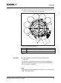
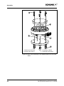
1
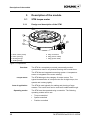
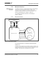
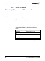
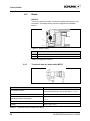
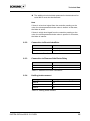
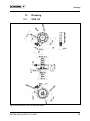
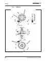
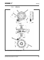
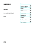
Electrical Rotary Module SCHUNK Torque Motor Type STM 560V Assembly and Operating manual 04/STM-560V/en/2010-12-10/SW Document last updated: 2010-12-03 2 04/STM-560V/en/2010-12-10/SW Dear Customer, Congratulations on choosing a SCHUNK product. By choosing SCHUNK, you have opted for the highest precision, top quality and best service. You are going to increase the process reliability of your production and achieve best machining results – to the customer’s complete satisfaction. SCHUNK products are inspiring. Our detailed assembly and operation manual will support you. Do you have further questions? You may contact us at any time – even after purchase. You can reach us directly at the mentioned addresses in the last chapter of these instructions. Kindest Regards, Your SCHUNK GmbH & Co. KG Precision Workholding Systems Bahnhofstr. 106 – 134 D-74348 Lauffen/Neckar, Germany Tel. +49-7133-103-2503 Fax +49-7133-103-2189 [email protected] www.schunk.com 04/STM-560V/en/2010-12-10/SW 3 Table of contents Table of contents 1 2 About this manual................................................................................................. 7 1.1 Purpose/validity .......................................................................................... 7 1.2 Target groups ............................................................................................. 7 1.3 Applicable documents ................................................................................ 7 1.4 Symbols in this manual .............................................................................. 8 1.5 Terms used in this manual ......................................................................... 8 Basic safety notes ................................................................................................ 9 2.1 Intended use .............................................................................................. 9 2.2 Environmental and operating conditions .................................................... 9 2.3 Controlled production ............................................................................... 10 2.4 2.5 2.3.1 Protective equipment ................................................................... 10 2.3.2 Constructional changes, attachments, or modifications ............... 10 2.3.3 After-sales service ....................................................................... 10 Obligations of the manufacturer/operator ................................................. 11 2.4.1 Choice of personnel and personnel qualifications ....................... 11 2.4.2 Organizational measures ............................................................. 11 2.4.3 Disposal ....................................................................................... 11 Personnel qualification ............................................................................. 12 2.5.1 Safety-conscious working ............................................................ 12 2.5.2 Safety measures during transport................................................ 12 2.5.3 Safety measures during operation ............................................... 12 2.5.4 Behaviour in the event of faults or emergencies .......................... 12 2.5.5 Notes on particular risks .............................................................. 13 3 Warranty .............................................................................................................. 15 4 Scope of delivery ................................................................................................ 15 5 Description of the module .................................................................................. 16 5.1 4 STM torque motor .................................................................................... 16 5.1.1 Design and description of the STM.............................................. 16 5.1.2 Mechanical interfaces .................................................................. 17 5.1.3 Electrical interface ....................................................................... 17 5.1.4 Type key and nameplate ............................................................. 18 04/STM-560V/en/2010-12-10/SW Table of contents 6 Technical Data .................................................................................................... 19 6.1 7 8 9 10 Technical Data des STM .......................................................................... 19 6.1.1 Technical Data STM135 .............................................................. 19 6.1.2 Technical Data STM170 .............................................................. 20 6.1.3 Technical Data STM210 .............................................................. 22 6.2 Requirements for the power and sensor cables ....................................... 23 6.3 Brake ........................................................................................................ 24 6.3.1 Technical data for brake valve MV15 .......................................... 24 6.3.2 Connection to Bosch IndraDrive .................................................. 25 6.3.3 Connection to Siemens Safe Brake Relay ................................... 25 6.3.4 Holding brake moment ................................................................ 25 Assembly ............................................................................................................. 26 7.1 Mechanical connection ............................................................................. 26 7.2 Electrical connection ................................................................................ 29 Start-up ................................................................................................................ 32 8.1 Start-up of the Bosch IndraDrive C .......................................................... 33 8.2 Start-up of the Siemens Sinamics S120 ................................................... 43 Control parameters ............................................................................................. 56 9.1 Bosch IndraDrive C - HCS02 series ......................................................... 56 9.2 Siemens Sinamics S120 series ................................................................ 57 Troubleshooting.................................................................................................. 60 10.1 SCHUNK torque motor STM .................................................................... 60 10.1.1 STM is not turning ....................................................................... 60 10.1.2 STM overspeed ........................................................................... 61 10.1.3 STM oscillates ............................................................................. 61 10.1.4 Bearing noise............................................................................... 61 10.1.5 Error message for the winding temperature ................................ 62 11 12 Maintenance and care ........................................................................................ 63 11.1 Maintenance and lubrication intervals ...................................................... 63 11.2 Disassembly of the module ...................................................................... 63 11.3 Module Servicing ...................................................................................... 64 Transport, storage and disposal ....................................................................... 65 12.1 Transport .................................................................................................. 65 04/STM-560V/en/2010-12-10/SW 5 Table of contents 13 12.2 Packaging ................................................................................................ 65 12.3 Storage..................................................................................................... 66 12.4 Disposal ................................................................................................... 66 Drawing................................................................................................................ 67 13.1 STM 135................................................................................................... 67 13.2 STM 170................................................................................................... 68 13.3 STM 210................................................................................................... 69 14 Translation of the EC declaration of conformity .............................................. 70 15 Contact ................................................................................................................ 71 6 04/STM-560V/en/2010-12-10/SW About this manual 1 1.1 About this manual Purpose/validity This manual is part of the module and describes the safe and proper use during all phases of operation. This manual is valid only for the module specified on the front page. 1.2 Target groups Target group Task Manufacturer, operator Keep this manual available for the personnel at all times. Require personnel to read and observe this manual and the applicable documents, especially the safety notes and warnings. Skilled personnel, fitter Read, observe and follow this manual and the applicable documents, especially the safety notes and warnings. Table 1 1.3 Applicable documents Document Purpose Catalog Technical data or application parameters of the module and information on accessories. The last version is always valid. (see www.schunk.com ) User manual pertaining to the utilized converter Contains further information on the converter firmware. This information is required for the control and parameterization of the STM torque motor. (Consult the homepage of the respective manufacturer) General terms of business Including notes on the warranty. (see www.schunk.com) Table 2 04/STM-560V/en/2010-12-10/SW 7 About this manual 1.4 Symbols in this manual To give you quick access to information, the following symbols will be used in this guide: Symbol DANGER Meaning Dangers for persons. Nonobservance causes death or serious injuries. WARNING Dangers for persons. Nonobservance can cause death or serious injuries. NOTICE Information on avoiding material damage. Prerequisite for a handling instruction. Handling instruction, also measures in a warning or note. 1. Step-by-step handling instruction. 2. Observe the order. 3. ... Component/spare part represented in a graphic. (10) Reference in the text or in a handling instruction to a part that is represented in a graphic. Table 3 1.5 Terms used in this manual Term Meaning Controller Frequency converter, controller, AC converter, servo converter, control system Table 4 8 04/STM-560V/en/2010-12-10/SW Basic safety notes 2 2.1 Basic safety notes Intended use The STM was designed to rotate loads, workpieces and objects. The STM may only be operated in combination with a controller. The module is intended for installation in a machine. The requirements of the applicable guidelines must be observed and complied with. The module may be used only in the context of its defined application parameters. To use this module as intended, it is also essential to comply with the manufacturer's specifications regarding commissioning, assembly, operation and ambient conditions. Any other use or use exceeding that specified is an infringement of use for intended purpose. The manufacturer bears no liability for damage resulting from such use. 2.2 Environmental and operating conditions The module may be used only in the context of its defined application parameters (see chapter 5, page 16 and catalog). Make sure that the module's range of application is outside the explosive area. Make sure that the environment is clean and the ambient temperature corresponds to the specifications per the catalog. Make sure that the environment is free from splash water and vapors as well as from abrasion or processing dust. Excepted are modules that are designed specially for contaminated environments. 04/STM-560V/en/2010-12-10/SW 9 Basic safety notes 2.3 Controlled production The module represents the state of the art and the recognized safety rules at the time of delivery. However, it can present risks if, for example: • The module is not used in accordance with its intended purpose. 2.3.1 • The module is not installed or maintained properly. • The EC Machinery Directive, the VDE directives, the safety and accident-prevention regulations valid at the usage site, or the safety and installation notes are not observed. Protective equipment When the module is in use, protective equipment must be used to catch flying parts or to switch the drive into a safe mode should the module or part of the module fail. The protective equipment must comply with the requirements of the EC Machinery Directive and IEC/EN 60204-1. The STM housing must be grounded via the converter by means of the protective conductor in the power cable. 2.3.2 Constructional changes, attachments, or modifications Additional drill holes, threads, or attachments that are not offered as accessories by SCHUNK may be attached only with permission of SCHUNK. Non-authorized modifications results in the exclusion from product liability. 2.3.3 After-sales service SCHUNK's after-sales service is available for technical information and questions concerning SCHUNK products. Call the contact. (see chapter 15 page 71) State the ID of the module. (see chapter 6.1, page 19 10 04/STM-560V/en/2010-12-10/SW Basic safety notes 2.4 2.4.1 Obligations of the manufacturer/operator Choice of personnel and personnel qualifications Work on the module may be carried out by authorized personnel only. The legal minimum age must be observed. The assembly, commissioning and repair of the module may be performed only by trained specialist personnel who have been instructed how to perform the said work activities. The manufacturer/operator must ensure that the personnel are adequately and appropriately trained to perform work on the module assigned to them. 2.4.2 Organizational measures Make sure that at least one copy of this manual is kept in the direct vicinity of the machine/system where the module is installed, and that it is accessible for the relevant persons. Ensure that personnel have read and understood this manual, especially chapter 2 "Basic safety notes". Provide instructions about and observe the safety and accident-prevention regulations that apply at the site of use. Provide instructions about and observe the environmental protection regulations that apply at the site of use. Provide protective equipment. Check the personnel’s conduct regarding the awareness of safety and hazards from time to time. 2.4.3 Disposal Send components of the module for recycling or properly dispose of them according to the local regulations. 04/STM-560V/en/2010-12-10/SW 11 Basic safety notes 2.5 2.5.1 Personnel qualification Safety-conscious working Avoid any manner of working that may interfere with the function and operational safety of the module. Observe the safety and accident-prevention regulations valid at the usage site. Wear protective equipment. 2.5.2 Safety measures during transport When transporting and handling very heavy modules, take the corresponding safety precautions. Make sure the cables have strain relief. 2.5.3 Safety measures during operation Only operate the module when all protective equipment has been fitted and is in full working order. Check the module at least once per shift for externally visible damage and faults. Report any changes including changes in operational behaviour to the responsible place/persons immediately. If necessary immediately shut down and lock out the machine/system. 2.5.4 Behaviour in the event of faults or emergencies If faults on the module occur which could impair safety or if the operational performance indicates the occurrence of a fault: Shut down the machine/system immediately, lock it and report the fault to the responsible place/persons. Faults may be eliminated by trained and authorized personnel only. Only restart the machine/system when the cause of the fault has been eliminated. 12 04/STM-560V/en/2010-12-10/SW Basic safety notes 2.5.5 Notes on particular risks Risk of injury from objects falling and being ejected! Provide protective equipment to prevent objects from falling or being ejected, such as processed workpieces, tools, chips, fragments, rejects. Adapt the operating conditions, e.g. reduce the velocity. Risk of injury when the machine/system moves unexpectedly! Do not move parts by hand when the energy supply is connected. Do not reach into the open mechanism or the movement area of the module. Remove the energy supplies before installation, modification, maintenance, or adjustment work. Perform maintenance, modifications, and additions outside the danger zone. For all work, secure the module against accidental operation. Risk of injury due to moving parts if these are controlled incorrectly! Possible causes for control errors: • • • • • • Incorrect cabling or wiring Removal of safety devices Software errors Sensor and signal transmitter errors Entry of incorrect parameters prior to start-up Defective module 04/STM-560V/en/2010-12-10/SW 13 Basic safety notes WARNING Risk of burns due to contact with hot surfaces! During operation, the surface temperature of the STM may exceed 85°C (185°F). Allow the module to cool down to at least 40°C (104°F) before working on the module. Measure the surface temperature before touching the module. Wear protective gloves, if necessary. Risk of electric shock due to contact with live parts! Before conducting work on the machine and the auxiliary equipment, disconnect them from the power supply and make sure they cannot be accidentally switched back on again. Wait until the intermediate circuit voltage of the converter has discharged completely (see the manufacturer's manual pertaining to the converter). 14 04/STM-560V/en/2010-12-10/SW Warranty 3 Warranty The warranty is valid for 24 months from the delivery date to the production facility under the following conditions: • Intended use in 1-shift operation • Observation of the maintenance intervals (see chapter 11, page 63) • Observation of the ambient conditions and operating conditions (see chapter 2.2, page 9) Also observe our general terms of business. The warranty does not cover the following: • Damage occurring as a result of incorrect operation. • Claims under warranty are excluded when repair or intervention is carried out by persons not authorized to do so. • If accessories are used which are not designed for the module. 4 Scope of delivery The scope of delivery includes: • Electrical Rotary Module Type STM in the version ordered • an exemplar of the Assembly and Operating manual incl. a translation of the EC declaration of conformity in accordance with the low voltage directive The following accessories are required for the module: • Cable set (power/sensor cables) The following accessories are available for the module: • Converter (Bosch IndraDrive C - HSC02 or Siemens Sinamics S120 CU310-DP) Order accessories separately. For additional accessories, see catalog or www.schunk.com. 04/STM-560V/en/2010-12-10/SW 15 Description of the module 5 5.1 5.1.1 1 2 3 4 Description of the module STM torque motor Design and description of the STM Basic carrier (fixed) Rotor (moving) Bearing flange Sealing flange 5 Plug connection 6 Plug (sensor cable) 7 Plug (power cable) Figure 1 Components Overview The STM is a completely mounted, permanently excited synchronous motor in a cylindrical housing with a center bore. The STM has an integrated measuring system. A temperature sensor is integrated in the motor winding. Torque motor Area of application Operating modes The STM belongs to the category of torque motors. The typical characteristics of a torque motor are its high torque, low speeds and a strong rigidity. The STM is used typically for rotating and pivoting of large masses. The center bore can be used as a media feed-through. The STM must be operated using a controller. The following operating modes can be set: • • • 16 Torque-controlled Speed-controlled Position-controlled 04/STM-560V/en/2010-12-10/SW Description of the module 5.1.2 Maintenance-free lubrication Mechanical interfaces The STM is mounted on a single Franke bearing. This bearing is lubricated via one-time grease lubrication. Under normal operating conditions lubrication for 20.000 operating hours is sufficient (see Maintenance in chapter 11 page 63). The mechanical interfaces are shown on the drawing in chapter 13 page 67. 5.1.3 Electrical interface Controller UVW + PE Supply voltage Encoder + Temp. Encoder values 8 Encoder system Encoder PE STM plug connection STM basic carrier U V 2 W Winding Temperature sensor KTY84 Figure 2 STM schematic diagram An incremental encoder (TTL signals) is installed as position feedback unit. In order to protect against impermissible operating conditions, the temperature sensor can be used to control the temperature in the windings. This data can be evaluated by the converter. 04/STM-560V/en/2010-12-10/SW 17 Description of the module 5.1.4 Type key and nameplate Order designation STMxxx - xxx - S - x - xx Size STM210 = d 210 mm STM170 = d 170 mm STM135 = d 135 mm voltage 560 = 560 V rated motor voltage cable version S = with plug connection for power component and encoder cable brake N = without brake B = with brake IP protection class 40 = IP40 protection class The nameplate is attached to one of the broad sides of the module. Designation Specification manufacturer SCHUNK GmbH & Co. KG type / model - protection class STM210-560-S-N-40 ID 03068xx rated torque (MN) 10 Nm voltage (UN) 560 V current (IN) 1,44 A Table 5 18 Data on the nameplate (example STM210) 04/STM-560V/en/2010-12-10/SW Technical Data 6 6.1 Technical Data Technical Data des STM Further technical data can be found in our catalog. The most recent version applies. 6.1.1 Technical Data STM135 Note All the technical data shown in the chart refer to the indicated heat conducting surface. Type STM135 560V ID 03068xx Heat conducting surface [mm²] 57686 Mechanical operating data deadweight [kg] 2,7 dimension (Ø x L) [mm] 135x 63 center bore (Ø) [mm] 15 ambient temperature [°C(°F)] min. +5(+41) max. +55(+131) mass moment of inertia of rotating parts [kg m²] 0,001431 max. mass moment of inertia [kg m²] 0,05 rotation range [°] >360 (turning endlessly) 1 positioning accuracy * [°] 0,02 1 * Distribution of the end positions of 100 successive motions. When approaching from the same direction. measuring system Incremental IP rating 40 permissible operating mode S1 - continuous operation* 2 *2 Applies only if the preconditions in chapter7.1, page 26 are fulfilled. Otherwise, S6 - continuous mode with intermittent load is the permitted operating mode. Electrical connection - required cable cross-sections and number of wire strands power [mm²] 3x1 grounding [mm²] 1x1 shaft encoder [mm²] 8 x 0,25 temperature sensor [mm²] 2 x 0,25 specifications for the integrated motor motor type synchronous switching star 04/STM-560V/en/2010-12-10/SW 19 Technical Data Type STM135 560V temperature sensor (type) KTY84 max. permissible operating temperature [°C(°F)] +85(+185) insulation class class F DIN 57530 output shaft power Pn [kw] 0,14 intermediate circuit voltage UZK [V] 560 rated torque Mn [Nm] 2,5 rated current In [A] 1,1 peak current Imax [A] 3,8 torque constant K [Nm/A] 1,9 rated speed nn [rpm] 600 max. speed nmax [rpm] 2300 winding resistance (phase-phase) R20 [Ohm] 26,5 winding inductivity (phase-phase) L20 [mH] 42,68 electrical time constant T [ms] 1,61 numbers of pole pairings N 15 Specifications for the integrated measuring system Type 1V Sin-Cos-Signal (analog), magnetic measuring system with reference track power supply [V] 5 ± 10 % mean current input [mA] 65 Number of poles 144 Table 6 6.1.2 Technical Data STM170 Note All the technical data shown in the chart refer to the indicated heat conducting surface. Type STM170 560V ID 03068xx Heat conducting surface [mm²] 49302 Mechanical operating data deadweight [kg] 4,7 dimension (Ø x L) [mm] 170 x 66 center bore (Ø) [mm] 32 ambient temperature [°C(°F)] min. +5(+41) max. +55(+131) 20 04/STM-560V/en/2010-12-10/SW Technical Data Type STM170 560V mass moment of inertia of rotating parts [kg m²] 0,003859 max. mass moment of inertia [kg m²] 0,14 rotation range [°] >360 (turning endlessly) 1 positioning accuracy * [°] 0,02 *1 Distribution of the end positions of 100 successive motions. When approaching from the same direction. measuring system Incremental IP rating 40 permissible operating mode S1 - continuous operation*2 *2 Applies only if the preconditions in chapter 7.1, page 26 are fulfilled. Otherwise, S6 - continuous mode with intermittent load is the permitted operating mode. Electrical connection - required cable cross-sections and number of wire strands power [mm²] 3x1 grounding [mm²] 1x1 shaft encoder [mm²] 8 x 0,25 temperature sensor [mm²] 2 x 0,25 specifications for the integrated motor motor type synchronous switching star temperature sensor (type) KTY84 max. permissible operating temperature [°C(°F)] +85(+185) insulation class class F DIN 57530 output shaft power Pn [kw] 0,74 intermediate circuit voltage UZK [V] 560 rated torque Mn [Nm] 5,0 rated current In [A] 1,6 peak current Imax [A] 5,65 torque constant K [Nm/A] 3,1 rated speed nn [rpm] 500 max. speed nmax [rpm] 1618 winding resistance (phase-phase) R20 [Ohm] 17,1 winding inductivity (phase-phase) L20 [mH] 24,9 electrical time constant T [ms] 1,46 numbers of pole pairings N 15 Specifications for the integrated measuring system type 1V Sin-Cos-Signal (analog), magnetic measuring system with reference track power supply [V] 5 ± 10 % mean current input [mA] 65 Number of poles 200 Table 7 04/STM-560V/en/2010-12-10/SW 21 Technical Data 6.1.3 Technical Data STM210 Note All the technical data shown in the chart refer to the indicated heat conducting surface. Type STM210 560V ID 03068xx Heat conducting surface [mm²] 37363 Mechanical operating data deadweight [kg] 7,8 dimension (Ø x L) [mm] 210 x 77 center bore (Ø) [mm] 40 ambient temperature [°C(°F)] min. +5(+41) max. +55(+131) mass moment of inertia of rotating parts [kg m²] 0,011278 max. mass moment of inertia [kg m²] 0,39472 rotation range [°] >360 (turning endlessly) 1 positioning accuracy * [°] 0,02 1 * Distribution of the end positions of 100 successive motions. When approaching from the same direction. measuring system Incremental IP rating 40 permissible operating mode S1 - continuous operation* 2 *2 Applies only if the preconditions in chapter 7.1, page 26 are fulfilled. Otherwise, S6 - continuous mode with intermittent load is the permitted operating mode. Electrical connection - required cable cross-sections and number of wire strands power [mm²] 3x1 grounding [mm²] 1x1 shaft encoder [mm²] 8 x 0,25 temperature sensor [mm²] 2 x 0,25 specifications for the integrated motor motor type synchronous switching star temperature sensor (type) KTY84 max. permissible operating temperature [°C(°F)] +85(+185) insulation class class F DIN 57530 output shaft power Pn [kw] 0,92 intermediate circuit voltage UZK [V] 560 22 04/STM-560V/en/2010-12-10/SW Technical Data Type STM210 560V rated torque Mn [Nm] 10 rated current In [A] 1,8 peak current Imax [A] 5,7 torque constant K [Nm/A] 5,6 rated speed nn [rpm] 400 max. speed nmax [rpm] 1000 winding resistance (phase-phase) R20 [Ohm] 16,6 winding inductivity (phase-phase) L20 [mH] 58,12 electrical time constant T [ms] 3,5 numbers of pole pairings N 16 Specifications for the integrated measuring system type 1V Sin-Cos-Signal (analog), magnetic measuring system with reference track power supply [V] 5 ± 10 % mean current input [mA] 65 Number of poles 200 Table 8 6.2 Requirements for the power and sensor cables cable type power sensor number of wires 4x1mm², 2x0,25mm² 8x0,25m² min. cross-section of the wires [mm²] 1 0,25 max. cable diameter [mm] 10 6 max. voltage [V] 600 24 shielded yes yes twisted no yes cable track compatible yes yes temperature application range [°C(°F)] max. cable length [m] (between STM and Controller) +5 to +55 (+41 to +131) +5 to +55 (+41 to +131) 20 20 Table 9 04/STM-560V/en/2010-12-10/SW 23 Technical Data 6.3 Brake NOTICE This is not a service brake. Its use as a safety component is not permitted. The brake merely serves to support the standstill torque. Figure 3 Brake design Pos. /1/ Contact surface between brake pad and rotor /2/ Pre-loaded brake piston with brake pad Table 10 Legend to Figure 4 6.3.1 Technical data for brake valve MV15 Figure 4 Valve assembly Reference value Permissible medium Nominal flow rate at 6 bar Operating pressure range [bar] Values Filtered compressed air, oiled or dry Compressed air purity classes ISO 8573 - 1 7 4 4 45 Nl/min P -1…1 Power consumption 2.8W Voltage 24V (+10% / -5%) Table 11 Technical data for brake valve MV15 24 04/STM-560V/en/2010-12-10/SW Technical Data The additional technical data presented in the data sheet for valve MV15 must also be observed. Note If there is a low level signal from the controller pending on the valve, the electropneumatic brake valve is closed. In this state, the brake is active. If there is a high level signal from the controller pending on the valve, the electropneumatic brake valve is opened. In this state, the brake is inactive. 6.3.2 Connection to Bosch IndraDrive Terminal Cable color, brake valve X6-3 +24V (red) X6-4 0V (black) Table 12 IndraDrive C connection 6.3.3 Connection to Siemens Safe Brake Relay Terminal Cable color, brake valve BR+ +24V (red) BR- 0V (black) Table 13 Sinamics CU310DP connection 6.3.4 Holding brake moment Motor type Holding brake moment [Nm] STM135 2.5 STM170 5 STM210 10 Table 14 Holding brake moment 04/STM-560V/en/2010-12-10/SW 25 Assembly 7 7.1 Assembly Mechanical connection WARNING Risk of injury when the machine/system moves unexpectedly! Switch off power supply. NOTICE Malfunctions due to mechanical stress in the housing possible Observe the requirements for the evenness of the mounting surface. Check the evenness of the bolting surface The values relate to the entire bolting surface. diameter [mm] Permissible unevenness [mm] < 100 < 0,02 > 100 < 0,05 Table 15 Requirements for levelness of the bolting surface Preconditions Depending on the load, the STM develops a very large heat quantity that needs to be dissipated: Mount the motor on heat-conducting materials. To achieve the IP protection class 40: Design the connection structure so that no chips, cooling water or dirt can enter the STM's connection area from the working area. Note If the unit has to be referenced via the measuring system's index track, and if the moving range is limited when the STM is installed, make sure that the basic carrier is aligned correctly in the machine. (see Figure 5, page 27) Align the zero point markings of the rotor and the base body so that they are at right angles on top of each other. 26 04/STM-560V/en/2010-12-10/SW Assembly Select the position of the STM in the machine so that the zero pulse is in the middle of the moving range. Figure 5 Zero pulse alignment Item Description /1/ Zero point markings on rotor and base body /2/ Maximum possible moving range Table 1 Assembly The interfaces to the attachments are clean and not damaged. The module is mounted to the machine via the corresponding interface. Six fastening screws are required for each fastening side. (see Figure 6, page 28) Note All dimensions of the drawings can be taken from our internet site under "CAD data service". 04/STM-560V/en/2010-12-10/SW 27 Assembly 1 - Fastening screws M10 2 - Centering pin D12/H7 3 - Centering pin D5/H7 4 - Fastening screws M12 Figure 6 View of the assembly of the adapter plates on rotor and basic 28 04/STM-560V/en/2010-12-10/SW Assembly 7.2 Electrical connection DANGER Risk of fatal injuries due to electric shock! Switch off power supply. Disconnect the controller from the power supply. The intermediate circuit capacitors must be discharged. Observe the sequence when connecting the cables (grounding cable first, then conductors) Only have the electrical connection established by the corresponding specialist personnel. Note Cables are electrical components which can receive and transfer interfering signals due to high-frequency interference or electromagnetic fields. Check that the cable is correctly connected and installed. There must be a sufficient distance between sources of interference and their supply cable. Preconditions for installing the connection cables: The cables are without tensile and torsion loads. Use cable guide chains. The minimum bending radius (7.5 times the cable diameter) is complied with (see chapter 6.1, page 19) The motor's range of rotation and functions are not impaired. Note More information on the parameters of the controller can be found in the separate operating manual for the controller. Electrical connection STM The STM is supplied with prefabricated cables (red power cable, white encoder cable), which need to be connected via the corresponding plug-in connections. The STM must be connected to a controller. The STM must be connected to a controller. 04/STM-560V/en/2010-12-10/SW 29 Assembly The cable colors and designations in the following tables apply to the SCHUNK connection cable. Observe the cable assignment. Function Power Temperature sensor Signal Cable designation U black U V black V W black W PE green/yellow T1 red T2 blue Table 16 Connection pin assignment of the red power cable for Bosch Function Encoder Signal Pin assignment - 15-pin D-Sub connector UB Pin 12 GND Pin 10 A Pin 7 /A Pin 8 B Pin 6 /B Pin 5 C Pin 4 /C Pin 3 Table 17 Connection pin assignment of the white signal cable for Bosch Indramat Function Power Signal Pin allocation - Siemens circular plug U U2 V V2 W W2 PE Table 18 Connection assignment of the power cable for Sinamics (connection to converter) 30 04/STM-560V/en/2010-12-10/SW Assembly Function Encoder Signal Pin allocation - Siemens 12-pin circular plug UB Pin 12 GND Pin 10/11 A Pin 5 /A Pin 6 B Pin 8 /B Pin 1 C Pin 3 /C Pin 4 Pin allocation - Siemens 6+1-pin circular plug Temperature sensor 1 -Temp 2 +Temp Table 19 Connection assignment of the encoder cable for Siemens SME120 04/STM-560V/en/2010-12-10/SW 31 Start-up 8 Start-up NOTICE Malfunction in the event of an overload! Avoid impact loads. Do not exceed the bearing load limits. NOTICE Malfunction in the event of overheating! Observe the motor’s technical data. (see chapter 6.1, page 19) WARNING Risk of injury and material damage when the machine/system moves unexpectedly Only allow configuration work to be carried out by authorized specialist personnel. Observe the information in the operating manual for the controller. WARNING Collisions in setup mode when the machine/system moves unexpectedly Keep the motor's moving range (360°) free. Starting up the STM with an arbitrary converter Connect the electrical connections (power cable, signal cable) to the converter. Check that the rotor can be turned freely. In doing so, pay attention to any grinding noise. Check that all required contact protection measures were taken for moving and live parts. 1. Switch on the converter and start the commissioning software. 32 04/STM-560V/en/2010-12-10/SW Start-up 2. Select the communication interface, establish communication with the module and configure the converter. 3. Check the encoder signal and the signal of the temperature sensor. 4. Control the STM and optimize the parameters. 5. Check the bearing noise at regular intervals. (see chapter 11.3, page 64) Note If the unit is referenced via the encoder's zero pulse, free motion must be ensured within the range of ± 360°. If the STM is used in a multiple axis system, it is recommended to put the axes into operation individually. To avoid collisions, prior to the first movement, check the alignment of the STM, the set direction of counting of the measuring system and the motor's direction of rotation. Note This brief instruction is solely relevant for the simple start-up of the STM with either the Bosch IndraDrive C or Siemens Sinamics. Please read the manuals for both converters thoroughly before putting the motor into operation. 8.1 Start-up of the Bosch IndraDrive C This description is valid for the firmware version MPH-05V12-D5 and the IndraWorks Version 8.6.172.0: Connection of the converter to the STM 1. Connect the converter to the three-phrase power network via terminal X1. 2. Connect the red power cable and the white sensor cable to the STM. 3. Connect the 15-pin D-Sub plug of the sensor cable to terminal X4. 4. Connect the free ends of the power cable to terminal X3. 04/STM-560V/en/2010-12-10/SW 33 Start-up Trafo necessary if the mains voltage > 240 V Mains necessary contactor Inductor optional GND Figure 7 connection des STM an IndraDrive C Setting up the converter 1. Connect the RS232 interface of the computer to the serial interface X2 of the converter using the serial cable. 2. Switch on the converter and power unit. 3. Start IndraWorks on the PC. Figure 8 Starting IndraWorks 34 04/STM-560V/en/2010-12-10/SW Start-up 4. Search for a new device: Figure 9 "Search devices“ 5. Select the interface on the converter. Figure 10 Selecting the interface 6. Select the interface on the computer. 04/STM-560V/en/2010-12-10/SW 35 Start-up Figure 11 7. When the desired device has been found, click on "Finish". Figure 12 8. A new project is created automatically in the project explorer: 36 04/STM-560V/en/2010-12-10/SW Start-up Figure 13 9. Import the parameter file supplied on the SCHUNK DVD: Figure 14 10. Open and start the Easy Start Up mode: Figure 15 04/STM-560V/en/2010-12-10/SW 37 Start-up 11. Enable the drive (STM) (this is only possible when the power unit is switched on). Figure 16 12. Read the warning attentively and acknowledge it by clicking "OK": Note In the case of the Bosch IndraDrive C converter, it can occur that the commutation current is too low or too high following enablement. If one of these errors occurs, simply delete it. Then go to the following location: "Drive control" "Motor control" "Commutation settings": 38 04/STM-560V/en/2010-12-10/SW Start-up Figure 17 13. Establish the new commutation offset: Figure 18 Note When the drive is enabled, a field appears in the foreground of the screen that can be used to switch off the drive (STM) in an emergency: Figure 19 04/STM-560V/en/2010-12-10/SW 39 Start-up 14. It is now possible to choose between the various options: Referencing – Referencing – Velocity movement – Positioning movement 1. Go to the following location: "Motor" "Motor encoder" "Motor encoder dimensional reference": Figure 20 2. Select the referencing type. Select the "Drive-guided referencing" field to start the reference movement: 40 04/STM-560V/en/2010-12-10/SW Start-up Figure 21 Velocity movement 1. Select the "Reference value box" under the "Optimization/Start-up" folder: Figure 22 2. Select the velocity movement type under "Operating mode". To start the movement, click on "Start": 04/STM-560V/en/2010-12-10/SW 41 Start-up Figure 23 Positioning movement 1. Select a "position-controlled" positioning movement under "Operating mode": Figure 24 Note With respect to the use of other functions: Refer to the manual pertaining to the IndraDrive C or contact the Bosch support team. 42 04/STM-560V/en/2010-12-10/SW Start-up 8.2 Start-up of the Siemens Sinamics S120 This description is valid for the firmware version MPH-05V12-D5 and the Drive ES - Starter version V4.1.2.0. Note With the Siemens Sinamics, it is possible to change the voltage supply on the encoder interface from 5V to 24V using a parameter. Ensure that the voltage supply on the encoder interface is set to 5V. Establishing the connection 1. Connect the motor with the converter: Figure 25 2. Connect the PC to the converter via a Profibus adapter. 3. Switch on the converter and power unit. 4. Initiate the Siemens Starter software: Figure 26 5. Search for available participants: 04/STM-560V/en/2010-12-10/SW 43 Start-up Figure 27 6. Select the checkbox (see black arrow) and adopt the settings by clicking on "Accept". Creating a new project 1. Start a new project using the wizard Figure 28 2. Assemble the drive control unit offline: 44 04/STM-560V/en/2010-12-10/SW Start-up Figure 29 3. Assign the project a name, e.g. "Start-up" Figure 30 4. The PG/PC interface has already been set to the Profibus adapter: 04/STM-560V/en/2010-12-10/SW 45 Start-up Figure 31 5. Select and integrate the drive unit. The bus address is dependent on the converter. Figure 32 6. Finish project: Figure 33 46 04/STM-560V/en/2010-12-10/SW Start-up Parameterizing the drive 1. Configure the drive unit (double click on "Configure drive unit") Figure 34 2. Select the control mode (simple positioner and speed control with encoder) Figure 35 3. Select the power unit (6SL3210-1SE14-1Uxx) 04/STM-560V/en/2010-12-10/SW 47 Start-up Figure 36 4. Select the drive (CU310DP): Figure 37 5. Enter the motor name, e.g. STM135 and select the DRIVECLiQ interface: 48 04/STM-560V/en/2010-12-10/SW Start-up Figure 38 6. Do not set up a motor holding brake: Figure 39 04/STM-560V/en/2010-12-10/SW 49 Start-up 7. Encoder 1 is preset: Figure 40 8. Adopt free telegram configuration with BICO: Figure 41 50 04/STM-560V/en/2010-12-10/SW Start-up 9. Finish: click Figure 42 10. Using the mouse, right-click on the drive and select the experts list. Figure 43 11. Important: Set parameter P340 to "no calculation". 12. Select "Open user-defined value list". Figure 44 13. Load the parameter file (e.g. STM135) from the relevant drive. 04/STM-560V/en/2010-12-10/SW 51 Start-up Figure 45 14. Adopt the values and then close the window. click Figure 46 15. Double click on the drive and select "Configure DDS". Figure 47 16. Perform the settings described in steps 2 and 3 again. 17. At step 4, select "Enter motor data". Proceed by confirming each window without making any adjustments. 52 04/STM-560V/en/2010-12-10/SW Start-up Figure 48 Connecting with the controller (going online) 1. Copy the data from the PC (PG) to the converter (target device): Figure 49 2. Copy the data from RAM to ROM (see arrows): 04/STM-560V/en/2010-12-10/SW 53 Start-up 1. 2. Figure 50 3. Following the copy procedure, select "Control panel" under "Start-up": Figure 51 4. Accept the safety note: click Figure 52 54 04/STM-560V/en/2010-12-10/SW Start-up 5. Enable the drive (STM): Select the checkbox next to "Enable". 6. The speed movement (n-reference setting) can be carried out: Figure 53 Note With respect to the use of other functions: Refer to the manual pertaining to the Siemens Sinamics S120 series or contact the Siemens support team. 04/STM-560V/en/2010-12-10/SW 55 Control parameters 9 9.1 Basic setting Control parameters Bosch IndraDrive C - HCS02 series 1. Set position controller to Kp = 0.5 2. Set velocity controller to Kp = 1; Tn = 0 3. Set current control to Kp = 30; Tn = 3 4. Set filter for speed control circuit Speed controller smoothing time constant = 0 Setting the velocity controller 1. In velocity mode, run the motor at a constant velocity of 15 rpm. 2. Increase the Kp incrementally by 0.5 until the motor begins to vibrate. 3. Reduce the vibrations by increasing the speed controller smoothing time constant. If this is not possible: Set the speed controller smoothing time constant to 0 and reduce the Kp until the vibrations cease. 4. Select the value that is half of the exact limit for Kp. 5. Select a high Tn value depending on the load 6. Reduce the Tn until the motor begins to vibrate. 7. Select the value that is double the exact limit for Tn. Setting the position controller Setting the current control 56 Increase the Kp until the desired positioning time is achieved. Be aware of overshooting! Increase the Kp until the current curve is as smooth as desired. (Make the current curve visible using the oscilloscope function) Be aware of noise emissions or vibrations! 04/STM-560V/en/2010-12-10/SW Control parameters 9.2 Siemens Sinamics S120 series Siemens provides the "Automatic controller settings" function for the purpose of establishing the control parameters. Figure 54 Select this function by clicking on the icon shown below... Figure 55 ...and accept the safety note: Figure 56 04/STM-560V/en/2010-12-10/SW 57 Control parameters Enable the drive: Figure 57 The individual steps required for determining the parameters can now be carried out. Parameter determination Figure 58 1. Ensure that no-one is positioned in the danger zone and that there is no potential for material damage. 2. Acknowledge the warning: Figure 59 The control parameters are now determined automatically. In the first two steps, the mechanism is measured in the upper and lower frequency ranges. 3. Acknowledge the subsequent warning: Figure 60 58 04/STM-560V/en/2010-12-10/SW Control parameters 4. Click on "Accept". Figure 61 5. Finally, acknowledge this acceptance so that the new parameters can be transmitted to the converter: Figure 62 The motor can now be operated with the new parameters. Note The Siemens auto tuning process selects a fairly hard converter setting, which can result in high noise emissions. To reduce the noise emission, it is recommended that the gain KP of the speed controller to reduce by 30-50%. 04/STM-560V/en/2010-12-10/SW 59 Troubleshooting 10 10.1 10.1.1 Troubleshooting SCHUNK torque motor STM STM is not turning Possible cause Corrective action Check the supply lines for defects Interruption in the supply lines No motion release Check the electrical connections (see chapter 7.2, page 29) Check the converter settings (see manual pertaining to the converter) Check whether there is voltage at the converter's output. If there is no voltage: Converter is defective a) Check the connection pin assignment (see chapter 7.2, page 29) b) see manual pertaining to the converter Target value line or communication between master and controller is interrupted Check the target value line and communication. Check the mechanical components. Rotor is blocked mechanically Shaft encoder defective Short-circuit between turns in the motor Check the evenness at the mounting surface (see chapter 7.1, page 26) Check shaft encoder and its connection. If a defect is detected, the STM must be sent to SCHUNK with a repair order. Check the difference of the winding resistance values. Do not exceed the difference. If the difference between the individual motor phases exceeds 0.1 Ohm, the STM must be sent to SCHUNK with a repair order. Check the protective conductor. Short-circuit to ground due to moisture short-circuit to ground due to electrical defect Check the electrical connection and connectors for ground leakage. If the STM has a ground leak while the power cable is disconnected, the STM must be sent to SCHUNK with a repair order. Incorrect phase connections Check the electrical connections (see chapter 7.2, page 29) Incorrect controller settings Check the parameters and setting values (see operating manual for the controller) 60 04/STM-560V/en/2010-12-10/SW Troubleshooting Possible cause Corrective action Motor phases or encoder signals confused Check the electrical connections (see chapter 7.2, page 29) Check the encoder signals and the shielding of the encoder cable. Table 20 10.1.2 STM overspeed Possible cause Corrective action Controller settings not ideal Check the controller settings (direction of rotation of motor and encoder direction of counting). Insufficient power supply for the controller's power component Check the stability of the supply voltage. Use transformers instead of a switching power supply component. Table 21 10.1.3 STM oscillates Possible cause Corrective action Motor overload Check the dimensioning Reduce the load Check the converter settings Converter settings not ideal Check the converter settings Table 22 10.1.4 Bearing noise Possible cause Corrective action Incorrect assembly Check the evenness at the mounting surface (see chapter 7.1, page 26) Configuration incorrect Check the parameters and setting values (see manual pertaining to the converter) Bearing defective due to overload Send the module to SCHUNK with a repair order. Table 23 04/STM-560V/en/2010-12-10/SW 61 Troubleshooting 10.1.5 Error message for the winding temperature Possible cause Corrective action The electrical connection to the temperature sensor is faulty Check resistance between the converter and the temperature sensor in the STM and replace the electrical connection, if necessary. Temperature sensor defective Check the resistance of the temperature sensor. If the resistance exceeds 630 Ohms at room temperature, the STM must be sent to SCHUNK with a repair order. Thermal motor overload Reduce the load. Mount the motor on heat-conducting materials to dissipate excess motor heat. Check the mechanical components. Rotor is blocked mechanically Check the evenness at the mounting surface (see chapter 7.1, page 26) Encoder signals are faulty; Check the encoder's power supply. encoder line shielding is not corrected. Check the encoder signals and the shielding of the encoder cable. Motor overload; Check the dimensioning. overvoltage or undervoltage Reduce the load. Check the converter settings. Check the output power supply. Table 24 62 04/STM-560V/en/2010-12-10/SW Maintenance and care 11 11.1 Maintenance and care Maintenance and lubrication intervals DANGER Risk of fatal injuries due to electric shock If the electrical connections are released from the live module, arcing may be the result. Switch off the energy supply. Only have work on the module performed by appropriately trained specialist personnel. NOTICE If the operating temperature in the motor's winding exceeds 60° C, the lubricants will harden faster. Lubrication and maintenance works have to be carried out more often. We recommend that maintenance and seal replacement is done by SCHUNK because the rotor must be aligned and assembled with an assembly device. Maintenance intervals Type STM 560V Bearing lubrication Interval [h] 20.000 Visual inspection [h] 2.500 Table 25 This information refers to the use of the STM under normal operating and ambient conditions: • • • 11.2 Clean workshop atmosphere No splashing water Small amounts of abrasive and process dust Disassembly of the module The module may only be disassembled and repaired by SCHUNK. Non-compliance will invalidate the warranty. 04/STM-560V/en/2010-12-10/SW 63 Maintenance and care 11.3 Module Servicing For maintenance work or repairs, send the complete module along with a repair order to SCHUNK. Visual inspection The regular visual inspection of all supply lines is the prerequisite for the perfect operation of the STM. If supply lines are defective, put the machine out of operation immediately. Replace damaged connection cables. Check the STM every 2500 operating hours or once a year for bearing noise: Acoustic bearing inspection Bearing noise Further procedure Smooth noise (typical bearing noise) Everything okay, STM can continue to be operated. Uneven grinding noise The motor is not set up correctly: check the evenness of the mounting surfaces (see chapter 7.1, page 26) Loud and uneven noise / motor not running smoothly The motor is not set up correctly: check the evenness of the mounting surfaces (see chapter 7.1, page 26) or bearings defective: Consult your SCHUNK contact and send the STM to SCHUNK along with a repair order. Table 26 Cleaning Clean the STM dry at regular intervals to remove all dirt. If the housing is soiled, please only rub it dry, e.g. with a cloth. Do not immerse or spray. When all maintenance work has been completed: Refit the safety devices provided, such as covers and safety switches. 64 04/STM-560V/en/2010-12-10/SW Transport, storage and disposal 12 12.1 Transport, storage and disposal Transport • • • • • • • • 12.2 The packaging must protect the drive from all external effects (such as mechanical shocks and humidity). Protect the module from shocks. Package the module in such a way that the electrical supply lines do not obstruct transport and are not damaged themselves. Comply with climatic category 2K3 in accordance with EN50178. Transport temperature -5°C (+23°F) to +60°C (+140°F), with maximum fluctuations of 20 K/hour. Transport air humidity: relative humidity of 5%-95%, noncondensing. During transport and handling, make sure that none of the components are bent or insulation space is changed. The STM contains components that are sensitive to electrostatic charge. Avoid any electrostatic charging of the STM. Packaging • • Cardboard packaging with paper foaming The maximum stacking height is three modules. 04/STM-560V/en/2010-12-10/SW 65 Transport, storage and disposal 12.3 12.4 Storage • Protect the drive (STM) against the effects of humidity. • The storage temperature should be between +5°C (+41°F) and +60°C (+140°F). • The storage location must be clean, dry and well ventilated. • No outdoor storage permitted. • No condensation permitted! • Comply with climatic category 1K4 in accordance with EN50178. • Observe the maximum stacking height of three packaged modules. Disposal • • • 66 Observe the locally valid legal disposal regulations. Environmentally sound disposal via the corresponding recycling or workshop centers. SCHUNK GmbH & Co. KG accepts no liability for the consequences of incorrect disposal by the customer. 04/STM-560V/en/2010-12-10/SW Drawing 13 13.1 Drawing STM 135 Figure 63 Dimensions of the STM torque motor 04/STM-560V/en/2010-12-10/SW 67 Drawing 13.2 STM 170 Figure 64 Dimensions of the STM torque motor 68 04/STM-560V/en/2010-12-10/SW Drawing 13.3 STM 210 Figure 65 Dimensions of the STM torque motor 04/STM-560V/en/2010-12-10/SW 69 Translation of the EC declaration of conformity 14 Translation of the EC declaration of conformity In terms of the EC Low Voltage Directive 2006/95/EC, annex III B Manufacturer/ distributor SCHUNK GmbH & Co. KG. Spann- und Greiftechnik Bahnhofstr. 106 – 134 D-74348 Lauffen/Neckar, Germany We hereby declare that the following product: Product designation: Electrical Rotary Module Type STM 560V Type designation: STM 135 / STM 170 / STM 210 Serial numbers: 0306830…0306838 / 0306840…0306848 / 0306850…0306858 , in its supplied condition, complies with the following relevant provisions: EC Low Voltage Directive 2006/95/EC, annex I EC Directive on Electromagnetic Compatibility (2004/108/EC, in this version 89/336/EEC) Applied harmonized standards, especially: EN ISO 12100-1 Safety of machinery - Basic concepts, general principles for design - Part 1: Basic terminology, methodology (ISO 12100-1:2003) EN ISO 12100-2 Safety of machinery - Basic concepts, general principles for design - Part 2: Technical principles (ISO 12100-2:2003) EN 60204-1:2006 Safety of machinery - Electrical equipment of machines - Part 1: General requirements (IEC 61000-6-2:2005 (modified)) EN 61000-6-2:2005 Electromagnetic compatibility (EMC) - Part 6-2: Generic standards Immunity for industrial environments (IEC 61000-6-2:2005) EN 61000-6-4:2007 Electromagnetic compatibility (EMC) - Part 6-4: Generic standards Emission standard for industrial environments (IEC 61000-6-4:2006) EN ISO 9409-1:2004 Manipulating industrial robots - Mechanical interfaces - Part 1: Plates (ISO 9409-1:2004); German version EN ISO 9409-1:2004 The following national or international standards (or parts/clauses contained therein) and specifications were applied: The last two digits of the year in which the CE marking was attached are: 10 Location, date/signature: Lauffen, October 2010 Title of the signatory Director for Development 70 p.p. 04/STM-560V/en/2010-12-10/SW Contact 15 Contact GERMANY – HEAD OFFICE CANADA DENMARK HUNGARY SCHUNK GmbH & Co. KG Spann- und Greiftechnik Bahnhofstrasse 106 – 134 D-Lauffen/Neckar Tel. +49-7133-103-0 Fax +49-7133-103-2399 [email protected] www.schunk.com SCHUNK Intec Corp. 190 Britannia Road East, Units 23-24 Mississauga, ON L4Z 1W6 Tel. +1-905-712-2200 Fax +1-905-712-2210 [email protected] www.ca.schunk.com SCHUNK Intec A/S Storhaven 7 7100 Vejle Tel. +45-43601339 Fax +45-43601492 [email protected] www.dk.schunk.com SCHUNK Intec Kft. Széchenyi út. 70. 3530 Miskolc Tel. +36-46-50900-7 Fax +36-46-50900-6 [email protected] www.hu.schunk.com AUSTRIA CHINA FRANCE INDIA SCHUNK Intec GmbH Holzbauernstr. 20 4050 Traun Tel. +43-7229-65770-0 Fax +43-7229-65770-14 [email protected] www.at.schunk.com SCHUNK Intec Precision Machinery Trading (Shanghai) Co., Ltd. Xinzhuang Industrial Park 479 Chundong Road Minhang District Shanghai 201108 Tel. +86-21-51760266 Fax +86-21-51760267 [email protected] www.cn.schunk.com SCHUNK Intec SARL Parc d´Activités des Trois Noyers 15, Avenue James de Rothschild Ferrières-en-Brie 77614 Marne-la-Vallée Cedex 3 Tel. +33-1-64 66 38 24 Fax +33-1-64 66 38 23 [email protected] www.fr.schunk.com SCHUNK Intec India Private Ltd. # 80 B, Yeswanthpur Industrial Suburbs, Bangalore 560 022 Tel. +91-80-40538999 Fax +91-80-41277363 [email protected] www.in.schunk.com BELGIUM, LUXEMBOURG CZECH REPUBLIC GREAT BRITAIN, IRELAND ITALY SCHUNK Intec N.V./S.A. Bedrijvencentrum Regio Aalst Industrielaan 4, Zuid III 9320 Aalst-Erembodegem Tel. +32-53-853504 Fax +32-53-836022 [email protected] www.be.schunk.com SCHUNK Intec s.r.o. Drážni 7 627 00 Brno Tel. +420-545 229 095 Fax +420-545 220 508 [email protected] www.cz.schunk.com SCHUNK Intec Ltd. Cromwell Business Centre 10 Howard Way, Interchange Park Newport Pagnell MK16 9QS Tel. +44-1908-611127 Fax +44-1908-615525 [email protected] www.gb.schunk.com SCHUNK Intec S.r.l. Via Barozzo 22075 Lurate Caccivio (CO) Tel. +39-031-4951311 Fax +39-031-4951301 [email protected] www.it.schunk.com 04/STM-560V/en/2010-12-10/SW 71 Contact JAPAN POLAND SOUTH KOREA SCHUNK Intec K.K. 45-28 3-Chome Sanno Ohta-Ku Tokyo 143-0023 Tel. +81-33-7743731 Fax +81-33-7766500 [email protected] www.tbk-hand.co.jp SCHUNK Intec Sp.z o.o. ul. Słoneczna 116 A Stara Iwiczna 05-500 Piaseczno Tel. +48-22-7262500 Fax +48-22-7262525 [email protected] www.pl.schunk.com SCHUNK Intec Korea Ltd. # 907 Joongang Induspia 2 Bldg., 144-5 Sangdaewon-dong Jungwon-gu, Seongnam-si Kyunggi-do, 462-722 Tel. +82-31-7376141 Fax +82-31-7376142 [email protected] www.kr.schunk.com MEXICO, VENEZUELA RUSSIA SPAIN, PORTUGAL TURKEY SCHUNK Intec S.A. de C.V. Calle Pirineos # 513 Nave 6 Zona Industrial Benito Juárez Santiago de Querétaro, Qro. 76120 Tel. +52-442-211-7800 Fax +52-442-211-7829 [email protected] www.mx.schunk.com OOO SCHUNK Intec ul. Samojlovoj, 5, lit. C St. Petersburg 192102 Tel. +7-812-326-78-35 Fax +7-812-326-78-38 [email protected] www.ru.schunk.com SCHUNK Intec S.L.U. Foneria, 27 08304 Mataró (Barcelona) Tel. +34-937 556 020 Fax +34-937 908 692 [email protected] www.es.schunk.com SCHUNK Intec Bağlama Sistemleri ve Otomasyon San. ve Tic. Ltd. Şti. Küçükyali Iş Merkezi Girne Mahallesi Irmak Sodak, A Blok, No: 9 34852 Maltepe, Istanbul Tel. +90-216-366-2111 Fax +90-216-366-2277 [email protected] www.tr.schunk.com NETHERLANDS SLOVAKIA SWEDEN USA SCHUNK Intec B.V. Speldenmakerstraat 3d 5232 BH ‘s-Hertogenbosch Tel. +31-73-6441779 Fax +31-73-6448025 [email protected] www.nl.schunk.com SCHUNK Intec s.r.o. Mostná 62 949 01 Nitra Tel. +421-37-3260610 Fax +421-37-6421906 [email protected] www.sk.schunk.com SCHUNK Intec AB Morabergsvägen 28 152 42 Södertälje Tel. +46-8 554 421 00 Fax +46-8 554 421 01 [email protected] www.se.schunk.com SCHUNK Intec Inc. 211 Kitty Hawk Drive Morrisville, NC 27560 Tel. +1-919-572-2705 Fax +1-919-572-2818 [email protected] www.us.schunk.com 72 SWITZERLAND, LIECHTENSTEIN SCHUNK Intec AG Im Ifang 12 8307 Effretikon Tel. +41-523543131 Fax +41-523543130 [email protected] www.ch.schunk.com 04/STM-560V/en/2010-12-10/SW


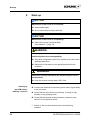

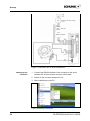

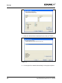
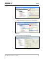
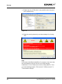
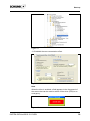
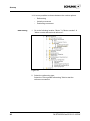
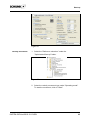
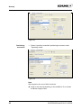
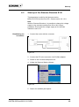
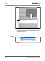
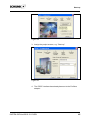
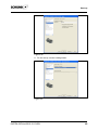
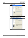
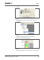
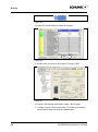
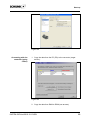


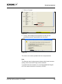


![[Download] azionamenti-hcs01](http://vs1.manualzilla.com/store/data/006141009_1-1242967de3765f3b826dc0b688197751-150x150.png)