1
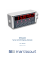
SERIALDIS
Serial ASCII Display Module
User Manual
mantracourt.com
Contents
SERIALDIS Overview .............................................................................................................2
Overview ...........................................................................................................................2
Requirements ................................................................................................................... 2
Configuration.................................................................................................................... 2
Operation ..........................................................................................................................2
Physical Connections ............................................................................................................2
Single PC Connection ....................................................................................................... 2
Multidrop RS232.............................................................................................................. 3
Multidrop RS485.............................................................................................................. 3
Configuration......................................................................................................................4
Error Reporting ...................................................................................................................4
Control Codes .....................................................................................................................4
Addressing .........................................................................................................................5
Display Examples .................................................................................................................5
Character Representations ....................................................................................................6
Specification ......................................................................................................................7
Environmental ....................................................................................................................7
CE Approvals ......................................................................................................................7
Warranty ...........................................................................................................................7
1
Mantracourt Electronics Limited SerialDis User Manual
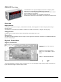
SERIALDIS Overview
The SERIALDIS is a 6 digit LED display module which displays ASCII
data sent to it via an RS232 or RS485 serial connection.
The device has addressing support so multiple devices can be driven
whilst residing on a serial bus.
Being a 7 segment display it is not possible to display all
alphanumeric characters so this display is primarily for numeric data.
Overview
Requirements
The module requires a serial input, either RS232 or RS485, which supplies the data to display followed by a
carriage return.
The baudrate is selectable from 9600 to 115200 but is fixed at 8 data bits, 1 stop bit and no parity.
Configuration
Configuration is by DIP switches where the baudrate and address can be set.
Operation
The display accepts ASCII data and on receipt of a carriage return character (decimal 13, hexadecimal 0D) the
data will be displayed.
Physical Connections
Single PC Connection
Connect power to The ‘Power In’
connector.
9
5
ON
Connect to the serial bus using
either J1 or J4 for RS232 or J2 for
RS485.
OFF
6
1
9 Way ‘D’ Socket RS232 Pinouts
View from inside case.
Pin
3
5
Function
RX (In)
GND
J4 has been designed to enable a quick connection to a PC for testing by using a 9 way D cable extension (pin
to pin) and connecting to the PC 9 way D socket.
Mantracourt Electronics Limited SerialDis User Manual
2
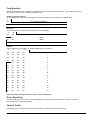
Multidrop RS232
ON
OFF
SW1 set for b aud rat e of 19200 and an ad d ress of 1 (left ) and 2 (right )
R S232 Serial D evice
TX
GND
GND
+V
Multidrop RS485
ON
OFF
SW1 set for b aud rat e of 38400 and an ad d ress of 8 (left ) and 9 (right )
R S485 Serial D evice
B
GND
A
+V
GND
+V
3
Mantracourt Electronics Limited SerialDis User Manual
Swit ch p osit ion 1 must b e on t o t erminat e RS485 b us. (Last d evice on b us)
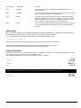
Configuration
RS485 Terminating resistor, baudrate and address can be selected by DIP switch SW1. The numbers at the top
of each table refer to the individual switches in SW1.
RS485 Terminator Resistor
On an RS485 bus the first and last modules on the bus should be terminated with a 120R resistor.
1
Off
No Terminating Resistor
On
120R Terminating Resistor Applied
Baudrate
Set the baudrate to match the data that will drive the display.
3
4
Off
Off
9600
Off
On
19200
On
Off
38400
On
On
115200
Address
Set the address of the display. To disable addressing set to all Off.
5
6
7
8
Off
Off
Off
Off
0
Off
Off
Off
On
1
Off
Off
On
Off
2
Off
Off
On
On
3
Off
On
Off
Off
4
Off
On
Off
On
5
Off
On
On
Off
6
Off
On
On
On
7
On
Off
Off
Off
8
On
Off
Off
On
9
On
Off
On
Off
10
On
Off
On
On
11
On
On
Off
Off
12
On
On
Off
On
13
On
On
On
Off
14
On
On
On
On
15
NOTE: DIP switch changes require a power cycle to implement.
Error Reporting
If no serial data arrives for within 10 seconds (default) the display will show NoData. As soon as new data
arrives this will be displayed instead.
Control Codes
Embedding control codes in the ASCII data can control certain functions of the display.
Mantracourt Electronics Limited SerialDis User Manual
4
Control Byte
Value Byte
Function
0x01
Address
The value byte contains the address of the display device to
send the data to.
0x02
Timeout
The value byte contains the new timeout period in seconds. This
can be between 0 and 30. The default is 10.
0x03
LEDs
The value byte contains value whose binary bit values indicate
whether to turn on or off the row of 4 LEDs. A value of 1 would
light the rightmost LED. A value of 8 would light the left most
LED. A value of 3 would light the two right hand LEDs.
0x04
Flash
The value byte indicates whether to flash the display. A value of
1 will cause the display to flash and a value of zero will stop it
flashing.
Addressing
Up to 15 display modules can be uniquely addressed on an RS232 or RS485 bus. To address a particular module
send the special control character 0x01 followed by a byte indicating the address.
i.e. To send data to display module addressed as 7 the following would be sent:
[0x01][0x07]123.456[0x0D]
Where the square brackets indicate a single byte whose value is shown in hexadecimal.
If data is sent with no addressing control bytes then all displays will show the data.
If a module is addressed as zero via SW1 then it will display all data.
Display Examples
Each piece of data sent to the display must end in a carriage return (decimal 13, hexadecimal 0x0D). For clarity
the carriage returns are not shown in the following table.
The following examples show the resulting display for data received:
123.4
123.4
-123.456
-123.456
-00123.4
-00123.4
Hello
Hello
WARNING: if more data is sent than will fit in the 6 digit display the right most portion will be shown. Take
care when sending numeric data that it is not too long otherwise integer digits will be lost.
-123.4567
23.4567
1234.56789
4.56789
5
Mantracourt Electronics Limited SerialDis User Manual
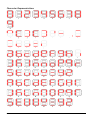
Character Representations
0
1
2
3
4
5
6
7
8
^
[
]
(
)
‘
-
.
:
;
<
>
=
,
a
b
c
d
e
f
g
h
i
j
k
l
m
n
o
p
q
r
s
t
u
v
w
x
y
z
A
B
C
D
E
F
G
H
I
J
K
L
M
N
O
P
Q
R
S
T
U
V
W
X
Y
Z
9
Mantracourt Electronics Limited SerialDis User Manual
6
Specification
Supply Voltage:
Nominal Voltage
Current Consumption:
Max
Communications:
RS232 and RS485
8 to 18V dc
200mA
8 data bits, 1 stop bit, no parity.
Environmental
Storage temperature
Operating temperature
Relative humidity
- 20 to +70ºC
-10 to 50ºC
95% maximum non condensing
CE Approvals
European EMC Directive
2004/108/EC
BS EN 61326-1:2006
BS EN 61326-2-3:2006
Warranty
All Wireless Telemetry products from Mantracourt Electronics Ltd., ('Mantracourt') are warranted against defective material and
workmanship for a period of (1) one year from the date of dispatch.
If the 'Mantracourt' product you purchase appears to have a defect in material or workmanship or fails during normal use within the period,
please contact your Distributor, who will assist you in resolving the problem. If it is necessary to return the product to 'Mantracourt' please
include a note stating name, company, address, phone number and a detailed description of the problem. Also, please indicate if it is a
warranty repair.
The sender is responsible for shipping charges, freight insurance and proper packaging to prevent breakage in transit.
'Mantracourt' warranty does not apply to defects resulting from action of the buyer such as mishandling, improper interfacing, operation
outside of design limits, improper repair or unauthorised modification.
No other warranties are expressed or implied. 'Mantracourt' specifically disclaims any implied warranties of merchantability or fitness for a
specific purpose. The remedies outlined above are the buyer’s only remedies. 'Mantracourt' will not be liable for direct, indirect, special,
incidental or consequential damages whether based on the contract, tort or other legal theory.
Any corrective maintenance required after the warranty period should be performed by 'Mantracourt' approved personnel only.
In the interests of continued product development, Mantracourt Electronics Limited reserves the right to alter product
specifications without prior notice.
Code No. 517-913
7
Mantracourt Electronics Limited SerialDis User Manual
Issue 1.2
11.04.14
Distribuidor
Brasil e América do Sul
C O N TA T O
Ender eço
Rua Sete de Setembro, 2671 - C entro
13560-181 - São C arlos - SP - Brasil
Telefone
+ 55 (16) 3371-0112
Metrolog Controles de Medição
Fax
+ 55 (16) 3372-7800
Inter net
www.metrolog.net
metrolog @metrolog.net
www.metrolog.net / mantracourt.com
[email protected]
tel +55 (16) 3371-0112