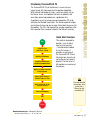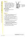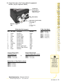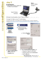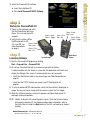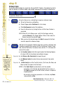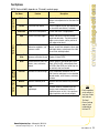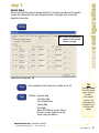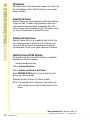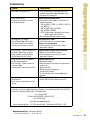
1
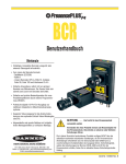
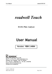
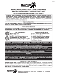
Models included:
•
GEO/GEO 1.3
GEO
• EDGE/EDGE
EDGE
1.3
• BCR/BCR 1.3
• AREA/AREA 1.3
• OMNI/OMNI 1.3
Printed in USA
12/04
02/06
P/N 118000 rev. D
A
WARNING . . .
Not To Be Used for Personnel Protection
Never use this product as a sensing device for personnel protection. Doing so could
lead to serious injury or death.
This product does NOT include the self-checking redundant circuitry necessary to allow its use in
personnel safety applications. A sensor failure or malfunction can cause either an energized or deenergized sensor output condition. Consult your current Banner Safety Products catalog for safety
products which meet OSHA, ANSI and IEC standards for personnel protection.
CAUTION . . . Electrostatic Discharge
Avoid the damage that electrostatic discharge (ESD) can cause to the Sensor.
Always use a proven method for preventing electrostatic discharge when installing a lens or attaching
a cable.
Banner Engineering Corp. • Minneapolis, MN U.S.A.
www.bannerengineering.com • Tel: 763.544.3164
P/N 118000 rev. D
sensorintroduction
Introducing PresencePLUS P4
The PresencePLUS P4 (or the Sensor) is an easy-to-use
vision sensor with advanced visual inspection capabilities.
With minimal knowledge of vision, a user can quickly set up
the Sensor to run an inspection that tests all products and
accurately rejects bad products on a production line.
Inspections are set up using a personal computer (PC) or by
activating the Remote Teach input. The Sensor captures images
and analyzes them using one or more Vision tools to pass or fail
the product. The PC is not required for running inspections after
the inspection files have been stored in the Sensor’s memory.
Quick Start Overview
Start
Install the Lens
(and Filters, if used)
Hook Up the Hardware
Install the Software and
Establish Communications
This guide is designed to
provide – even to those
new to vision sensing
– the information needed
to use this sensor. It
provides an overview of
the PresencePLUS P4 and
illustrates how to easily set
up the Sensor to inspect a
product. The flow chart at
left provides an overview of
the process.
Acquire an Image of the Part
Being Inspected
Choose Vision Tool(s) to
Find the Feature or Flaw
Add a Test Tool To Set Up
Pass/Fail Criteria
Teach Good Examples
TIPS
For more detailed
instructions, refer
to the User’s
Manual on the
installation CD.
Run
Finish
Banner Engineering Corp. • Minneapolis, MN U.S.A.
www.bannerengineering.com • Tel: 763.544.3164
P/N 118000 rev. D
components/connections
step 1
1. Install the lens (and filters, if used).
For EDGE, GEO, BCR, AREA, and OMNI any
lens may be used. For EDGE 1.3, GEO 1.3,
AREA 1.3, BCR 1.3, and OMNI 1.3 use only
Megapixel lenses. For non-Banner lenses,
follow the lens manufacturer’s unpacking
and installation instructions.
Aperture Lock
Screw
Focusing
Ring
NOTE: If the lens has a focus
lock screw, loosen the
screw before focusing
the lens. Some lenses
also have an aperture
lock screw.
Focus
Lock Ring
Cable Connections
1.If a light will be powered by the Sensor,
connect it to the
Light connector.
step 2
a. Caution: If the light is powered by the Sensor, the
Sensor power source must be 24V dc.
b. Caution: This connection is for Banner lights only!
2.If an NTSC monitor is used, connect it to the Sensor via a
BNC-to-BNC cable to the NTSC Video connector.
3.Connect the Ethernet cable from your PC to the Sensor at
the RJ-45 connector.
a. If connecting directly from the PC, use a crossover
cable (such as Banner Model No. STPX07).
b. If connecting the Sensor to a hub or router, use
straight cables (such as Banner Model No. STP07) to
the Sensor as well as to the PC.
4.Push the connector end of the supplied 12-wire cable
onto the 12-pin connector on the Sensor.
Banner Engineering Corp. • Minneapolis, MN U.S.A.
www.bannerengineering.com • Tel: 763.544.3164
P/N 118000 rev. D
components/connections
5.Connect the leads on the 12-wire cable to the appropriate
locations (see pin assignments below).
12-pin Discrete
I/O Power/Ground
RS-232 Serial (see pin
assignments below)
Ethernet (RJ-45)
Light Connector (3-pin Pico Style)
(Banner lights only)
1 = Brown 24V
2 = n/a
3 = Blue (ground)
4 = Strobe
NTSC Video
(BNC)
12-Wire Cable Pin Assignments
12-Wire Cable Models
Pin # Wire Color
Description
Direction
1
2
3
4
5
6
7
8
9
10
11
12
RS-232 TX
Remote Teach
Product Change
External Trigger
Discrete I/O #1
Discrete I/O #2
Discrete I/O #3
Discrete I/O #4
RS-232 RX
RS-232 Signal Ground
Common (Signal Ground)
10-30V dc
Output
Input
Input
Input
In/Out
In/Out
In/Out
In/Out
Input
Output
Input
Input
Yellow
Gray
Orange
Pink
Black
Red
White
Light Blue
Violet
Green
Blue
Brown
Crossover Ethernet Cable
(to PC Ethernet Port)
STPX07 — 2.1 m (7')
STPX25 — 7.6 m (25')
or
P4C06 — 2 m (6')
P4C23 — 7 m (23')
P4C32 — 10 m (32')
P4C50 — 16 m (50')
P4C75 — 23 m (75')
Standard Ethernet Cable
(to PC via Network Hub or Switch)
STP07 — 2.1 m (7')
STP25 — 7.6 m (25')
Monitor Cable (to Video Monitor, optional)
BNC06 — 2 m (6')
BNC15 — 5 m (15')
BNC30 — 9 m (30')
TIPS
The trigger device
can be any
10-30V dc
photoelectric
sensor, or a
device with a
similar output.
Banner Engineering Corp. • Minneapolis, MN U.S.A.
www.bannerengineering.com • Tel: 763.544.3164
P/N 118000 rev. D
sensorconfiguration
step 3
Sensor
Default IP Address
192.168.0.1
PC Configuration
1. E thernet communication, configure the
IP address of your computer.
Typical IP Address:
192.168.0.2
Write down the existing address of your PC before changing it: _ _ _ • _ _ _ • _ _ _ • _ _ _
To change the IP address of your PC, do the following:
The following screen captures are from Windows XP. For earlier Windows versions, see Banner’s Supplemental
Information at http://info.bannersalesforce.com/xpedio/groups/public/documents/trainingjobaid/vr_01_00_e.pdf.pdf
a.Select Start
> Settings
> Network
Connections.
b.Double-click the Local
Area Connection used by
PresencePLUS.
d.Highlight Internet Protocol
TCP/IP, and click the
Properties button.
c. Click the Properties
button.
e.Choose Use the following IP address, and:
• Change the IP address to 192.168.0.2
• Change the Subnet mask to 255.255.255.0
• Click the OK button.
Banner Engineering Corp. • Minneapolis, MN U.S.A.
www.bannerengineering.com • Tel: 763.544.3164
P/N 118000 rev. D
a. Insert the Installation CD.
b. Click Install PresencePLUS PC Software.
step 4
Starting the PresencePLUS P4
1. P
ower up the hardware and verify
that the Power/Error light turns
Green. This may take up to 20
seconds.
Green = Ready
Yellow = Trigger
2. Verify that the yellow LED on
the Ethernet port is ON.
Green = Power
If it is not ON, see
Red = Error
Cable Connections
on page 4.
Green = Pass
Green = Pass
Red = Fail
Green = Power
Red = Error
Green = Ready
Yellow = Trigger
sensorstartup
2. Install the PresencePLUS software.
Red = Fail
step 5
Launching Software
In-Line Sensor
Right-Angle
Sensor
1. S
tart the PresencePLUS program by clicking
Start > Program Files > PresencePLUS.
2. At start-up, PresencePLUS will try to communicate with the Sensor.
If communication with the Sensor is successful, the application will launch and
display the Setup or Run screen. If communication was not successful:
• V
erify that the Ethernet cable is the correct type (see Cable Connections on
page 4).
• V
erify that the TCP/IP settings are correct (see PC Configuration on
page 6).
3. If using an optional NTSC video monitor, verify that the monitor is displaying an
image. You may not see an image until the camera is given the first trigger.
4. When the software launches, create an inspection, configure the discrete I/O,
and begin running inspections.
NOTE: Initially, all discrete I/O are configured as inputs. Go to the System window
to change the discrete I/O. For detailed configuration information, refer to
the User’s Manual (under the Help button in the GUI; see back cover for part
number).
Banner Engineering Corp. • Minneapolis, MN U.S.A.
www.bannerengineering.com • Tel: 763.544.3164
P/N 118000 rev. D
creatinginspections
step 6
Software Setup
Use the Main Menu toolbar to navigate the PresencePLUS P4 options. Proceeding from left to
right, the buttons in the Menu toolbar step through the process of creating an inspection file.
Inspection Work Flow
1.
Set up the Sensor, lens, and lighting, to acquire a reference image.
a. Set up the Sensor lens and lighting.
b. Choose Trigger option Continuous for a live image.
c. Click Auto Exposure to adjust the brightness.
d.Focus the Sensor lens by turning the lens until the Focus Number is
maximized.
NOTE: While still in the Setup screen, verify that the trigger works by
selecting External in the Trigger Options. When in Run mode, the
Sensor uses only the external trigger.
e.When you have the desired image, click Next to proceed to the Tools
screen to acquire the reference image.
2.
Add tools to the inspection. Build the tools from scratch or add tools from
a previous inspection file saved on the PC or the Sensor. To add a Vision
tool, click the Tool button. To remove a tool, click the “X” in the lower left
corner of the screen.
a.Add Location tool(s) to find the target to adjust the following Regions
of Interest (ROI) for transitional and rotational changes.
TIPS
Before creating an
inspection file, set
up the electrical
configuration
of the external
trigger. (Click
System button,
select
Trigger tab.)
Required b. Add Vision or Bar Code tool(s) to inspect the part.
c. Add Measure tool(s) to create distance measurements from points
found.
Required d.Add Test tool(s) to set the Pass/Fail criteria. (The Vision, Bar Code, and
Measure tools are inputs to the Test tool.)
NOTES: • C
lick Quick Teach to automatically set all the selected
parameters in the Test tool and proceed to the Run screen, or
click Next to proceed to the Teach screen, to teach a sample set
of good products.
•T o manually set min/max parameters in a Test tool, skip Teach
and go directly to Run.
Banner Engineering Corp. • Minneapolis, MN U.S.A.
www.bannerengineering.com • Tel: 763.544.3164
P/N 118000 rev. D
creatinginspections
Tool Options
NOTE: Tool availability depends on P4 model; see back page.
Location Tools
Tool Name
Translation and rotation
Locates the target by searching for a taught
pattern and compensates for translation and
rotation.
Locate
Translation and rotation
Finds the edge of the part and compensates
for translation and rotation (if selected).
Finds one or more patterns
Locates and counts a taught pattern.
Counts and locates edges
Detects and counts transitions between
bright and dark pixels. The total number of
edges can be counted, and the position of
each edge can be found.
Object
Locates and counts objects,
determines midpoints, and
measures widths
Detects the edges of dark and bright
objects, locates their midpoints, counts dark
and bright objects, and measures the width
of each dark and bright object.
Average Gray
Scale
Determines presence,
absence, and shades of gray
Determines average gray scale value in the
Region of Interest (ROI)
BLOB
Counts/measures areas and
counts, sizes, and locates
objects
Detects groups of connected light or dark
pixels within the ROI and designates them
as BLOBs. After BLOBs are found, they can
be counted, sized, and located.
Bar Code
Decodes bar code markings
Finds and decodes DataMatrix, PDF-417,
and Linear bar code types in user-selectable
decoder modes, color schemes, and viewer
schemes.
Measure
Measures between points
Measures distance between two prescribed
points.
Logic input/output
Evaluates results of selected Vision and
Analysis tools to determine whether an
inspection passes or fails. It also performs
logical operations and activates outputs.
Vision Tools
Edge
Bar Code
Reader
Description
GEO Find
GEO Count
Analysis Tools
Function
Test
TIPS
• Each inspection
must contain at
least one Vision
tool and one
Test tool.
• Save a backup
copy of your
inspection to
the host PC.
Banner Engineering Corp. • Minneapolis, MN U.S.A.
www.bannerengineering.com • Tel: 763.544.3164
P/N 118000 rev. D
runninginspections
3.
This screen automatically configures the parameters chosen in the
Tools screen.
a. Choose the sample size
b. Click Start
c. Trigger the controller with the external trigger device
d. Click Stop
e. Click Next to proceed to Run
Before entering Run, save the inspection file to one of the 12 memory
locations on the Sensor.
4.
Select an inspection to run, and view the results of the inspection.
To select an inspection, (in the Select tab) enable Software Override and
select the inspection file from the list of stored inspections.
Alternate method: Use Hardware Input to select an inspection via Product
Change and Product Select lines.
Viewing Results
Display Options
Next Pass
Display only the next passing inspection.
Next Fail
Display only the next failing inspection.
Next RT
Display the next remote teach.
Next RT Fail
Display the next unsuccessful remote teach.
Next
Continuously display inspections.
None
Don’t display any inspections.
TIPS
When using the
Hardware input,
pulse the Product
Change and
Product Select
inputs to initiate
an inspection
change. See the
User’s Manual in
the Help menu
for complete
information.
Click + to
expand and
– to contract
category
Click on
tool name
to show
the ROI
Passing
Tool
Failing
Tool
To begin inspecting, click the Start button in the Run screen.
Banner Engineering Corp. • Minneapolis, MN U.S.A.
10
www.bannerengineering.com • Tel: 763.544.3164
P/N 118000 rev. D
System Setup
Use the System Setup screen to change discrete I/O, the communication port, the product
change, the strobe output (for external lighting control), the trigger input, and to view
diagnostic information.
NOTE: To select the polarity of the
outputs, set one of the four
I/O pins to an output.
sensorconfiguration
step 7
InputOutput Configuration Tab
Save inspections to the Sensor or to a folder on the PC.
Provides:
Operation Help
Installation Help
Lens Selection Help
Lighting Help
Error Codes
About (GUI Software version, Sensor
Firmware version, Hardware version,
Sensor’s physical address)
TIPS
Use Help > About
in the GUI to look
up the software,
firmware,
and hardware
versions. The
information will
be helpful if you
call Banner for
support.
Banner Engineering Corp. • Minneapolis, MN U.S.A.
www.bannerengineering.com • Tel: 763.544.3164
P/N 118000 rev. D
11
sensormaintenance
Maintenance
Maintenance tasks include keeping the hardware free of dust and
dirt and updating the PresencePLUS software as new versions
become available.
Cleaning the Sensor
Regularly remove any accumulated dust or dirt from the Sensor
using a soft cloth. If needed, slightly dampen the cloth with a
weak solution of neutral detergent. Avoid getting dirt on the
Sensor’s imager (the area behind the lens). If the imager is dirty,
use anti-static compressed air to blow off the dust.
Cleaning the Sensor Lens
Regularly remove dust, dirt, or fingerprints from the lens. Use
anti-static compressed air to blow off dust. If necessary, use
a lens cloth and lens cleaner or window cleaner to wipe off
remaining debris. Do not use any other chemicals for cleaning.
Updating PresencePLUS Software
The current version of PresencePLUS software is available for
download from the Banner website:
www.bannerengineering.com
Click on Literature/Resources.
Click on Software and Electronic Data Sheets.
Select PRESENCEPLUSP4 from the Vision Product Line pulldown menu, and click on Go!
Download the latest Firmware, PC software, or both.
NOTE: If you upgrade the PC software only, new features may
not be available until you load the latest firmware to the
Sensor.
Banner Engineering Corp. • Minneapolis, MN U.S.A.
12
www.bannerengineering.com • Tel: 763.544.3164
P/N 118000 rev. D
Problem
Cause/Solution
• Error Code is displayed on PC.
• A list of error codes and potential causes and
solutions are available under Help/About on the
PresencePLUS software CD.
• Power light is not ON.
• Interface cannot connect to Sensor.
• No image on monitor.
Sensor not getting enough power
• Verify that the power supply is 10–30V dc with
maximum current of
550 mA (GEO 1.3, EDGE 1.3, AREA 1.3, BCR 1.3,
and OMNI 1.3)
500 mA (GEO, EDGE, and AREA)
650 mA (BCR and OMNI)
NOTE: If light source is powered by the Sensor,
power supply must be 24V dc.
• Check the connection to the power supply.
• No image on PC or monitor.
• Sensor Ready/Trigger LED is Green.
• The software seems to be working
correctly, but the image is missing.
Run display set to “None”
• Verify that the Sensor is receiving triggers.
Sensor not receiving triggers
• If the connections are secure, call a Banner
Applications Engineer.*
• Error message, “Failed to capture a fullresolution image. Please try again.”
• Image is frozen on PC and monitor.
• Sensor Power/Error LED is Red.
Software restart needed or loose connections
• Restart the PresencePLUS software.
• If the connections are secure, call a Banner
Applications Engineer.*
• Image is frozen on PC, but image on
monitor properly updates.
• Error message, “Failed to capture fullresolution image.”
• Indicator lights on RJ-45 port are OFF.
Ethernet connection lost
• Reconnect the cable.
• Check the cable for any breaks, then power down
and back up.
• Replace the cable.
• Attempt to close and reopen the
PresencePLUS software.
• If still not resolved, call a Banner Applications
Engineer.*
• Focus number does not update.
• QuickStart fails.
• Errors when saving inspections to the
Sensor.
FTP communications blocked
• Disable TCP/IP Firewall software on the PC.
sensortroubleshooting
Troubleshooting
*Support is available from your local Banner representative or a Banner Applications Engineer. Call,
e-mail, fax, or write for support. Applications Engineers are available from 8:00 A.M. to 5:00 P.M.
Central Time, Monday through Friday, excluding holidays.
Local: 763.544.3164
Toll free: 1.888.3.SENSOR (1.888.373.6767)
Fax: 763.544.3213
[email protected]
Banner Engineering Corp. • 9714 10th Avenue North • Minneapolis, MN 55441 • USA
Banner Engineering Corp. • Minneapolis, MN U.S.A.
www.bannerengineering.com • Tel: 763.544.3164
P/N 118000 rev. D
13
sensorspecifications
Specifications
Right-Angle Housing
Models
Dimensions
*Measured length does not
include connectors or cables
GEO:
GEO 1.3:
EDGE:
EDGE 1.3:
BCR:
BCR 1.3:
AREA:
AREA 1.3:
OMNI:
OMNI 1.3:
In-Line Housing
GEO:
GEO 1.3:
EDGE:
EDGE 1.3:
BCR:
BCR 1.3:
AREA:
AREA 1.3:
OMNI:
OMNI 1.3:
P4GR
P4G1.3R
P4ER
P4E1.3R
P4BCR
P4BC1.3R
P4AR
P4A1.3R
P4OR
P4O1.3R
H x W x L:
55.6 x 66.8 x 124.5* mm
(4.9" x 2.63" x 2.2")
P4GI
P4G1.3I
P4EI
P4E1.3I
P4BCI
P4BC1.3I
P4AI
P4A1.3I
P4OI
P4O1.3I
H x W x L:
34.3 x 66.8 x 147.3* mm
(1.35" x 2.63" x 5.8")
Construction: Black anodized aluminum
Weight: Approximately 0.29 kg (0.642 lb.)
Mechanical
Environmental Rating: IEC IP20; NEMA 1
Operating Temperature: 0˚ C to +50˚ C (+32˚ F to +122˚ F)
Maximum Relative Humidity: 90%, non-condensing
Display Options
Discrete I/O
PC or NTSC video (9 m [30'] max. cable length)
1 Remote Teach IN (pin 2)
4 Programmable I/O (pin 5-8)
1 Product Change IN (pin 3)
1 Strobe OUT (light connector pin 4)
1 Trigger IN (pin 4)
Output Configuration
NPN or PNP software selectable
150 mA (each)
ON-State Saturation Voltage: < 1V at 150 mA max. NPN
> V+ - 2 volts
OFF-State Leakage Current: <100 microamps NPN or PNP
Output Rating
NPN Hookup
PNP Hookup
–
10-30V dc
+
Load
Communication
+
10-30V dc
–
Load
• 1 RJ-45 Ethernet
• RS-232 flying leads
Banner Engineering Corp. • Minneapolis, MN U.S.A.
14
www.bannerengineering.com • Tel: 763.544.3164
P/N 118000 rev. D
Memory
Stores up to 12 inspection files, depending on the P4 model
Voltage:10-30V dc
Current:
Power
GEO, EDGE, AREA:
500 mA max.
BCR, OMNI:
650 mA max.
GEO 1.3, EDGE 1.3, AREA 1.3, BCR 1.3, OMNI 1.3: 550 mA max.
Frames Per Second:
GEO, EDGE, AREA:
500 max.
BCR, OMNI:
48 max.
GEO 1.3, EDGE 1.3, AREA 1.3, BCR 1.3, OMNI 1.3: 26.8 max.
Acquisition
Image Size:
GEO, EDGE, AREA:
128 x 100 pixels
BCR, OMNI:
640 x 480 pixels
GEO 1.3, EDGE 1.3, AREA 1.3, BCR 1.3, OMNI 1.3: 1280 x 1024 pixels
Levels of Gray Scale: 256
Exposure Time
GEO, EDGE, AREA:
0.01 ms to 20.47 ms
BCR, OMNI:
0.1 to 2830 ms
GEO 1.3, EDGE 1.3, AREA 1.3, BCR 1.3, OMNI 1.3: 0.1 ms to 1670 ms
GEO, EDGE, AREA:
2.56 x 2.00 mm, 3.2486 mm diagonal CMOS; 128 x 100 pixels
Imager
BCR, OMNI:
4.736 x 3.552 mm, 5.9200 mm diagonal CCD; 640 x 480 pixels
sensorspecifications
Specifications, continued
GEO 1.3, EDGE 1.3, AREA 1.3, BCR 1.3, OMNI 1.3:
8.576 x 6.861 mm, 10.9829 mm diaganol CMOS; 1280 x 1024 pixels
Pixel Size
GEO, EDGE, AREA:
20 x 20 micrometers
BCR, OMNI:
7.4 x 7.4 microns
GEO 1.3, EDGE 1.3, AREA 1.3, BCR 1.3, OMNI 1.3: 6.7 x 6.7 micrometers
Lens Mount
GEO, EDGE, BCR, AREA, OMNI:
C-mount
GEO 1.3, EDGE 1.3, AREA 1.3, BCR 1.3, OMNI 1.3: Megapixel C-mount
Certifications
Banner Engineering Corp. • Minneapolis, MN U.S.A.
www.bannerengineering.com • Tel: 763.544.3164
P/N 118000 rev. D
15
Models/Tools
User’s
Manual
Part
Number*
Locate
GEO/GEO 1.3
117020
X
EDGE/EDGE 1.3
120413
X
BCR/BCR 1.3
122800
X
AREA/AREA 1.3
125439
X
X
X
OMNI/OMNI 1.3
125808
X
X
X
PresencePLUS
P4 Models
Tools
Avg.
Gray
BLOB
GEO
Find
GEO
Count
X
X
EDGE
X
Object
Bar Code
Reader
X
X
X
X
X
X
X
(optional)
Measure
Test
Comm.
X
X
X
X
X
X
X
X
X
X
X
X
X
X
X
*Available on enclosed CD or online at www.bannerengineering.com.
Banner Engineering Corp.,
9714 Tenth Ave. No.
Minneapolis, MN 55441
Phone: 763.544.3164
www.bannerengineering.com
Email: [email protected]
P/N 118000 rev. D