1
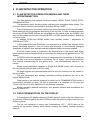
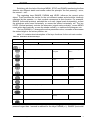
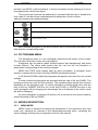
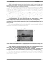
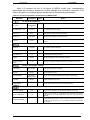
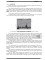
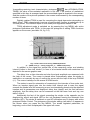
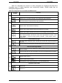
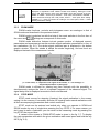
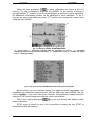
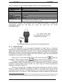
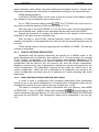
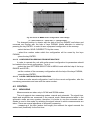
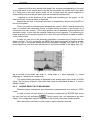
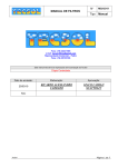
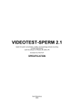
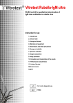
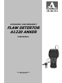
ULTRASONIC LOW-FREQUENCY
FLAW DETERTOR
A1220 ANKER
USER MANUAL
Acoustic control systems
Moscow 2006
User manual
A1220 ANKER
CONTENTS
1
2
3
MAIN DATA ..................................................... Ошибка! Закладка не определена.
1.1
List of abbreviations .......................................... Ошибка! Закладка не определена.
1.2
Purpose ............................................................... Ошибка! Закладка не определена.
1.3
Scope .................................................................. Ошибка! Закладка не определена.
UNIT AND KITTING ................................................................................................. 5
2.1
Electronic block.........................................................................................................5
2.2
Transducer .......................................................... Ошибка! Закладка не определена.
FLAW DETECTOR OPERATION .................... Ошибка! Закладка не определена.
3.1
Flaw detector operation modes and their interconnection ....................................7
3.2
Data presentation on the display .............................................................................7
3.3
Keyboard ............................................................. Ошибка! Закладка не определена.
3.4
Pictograms menu .................................................................................................... 10
3.5
Modes description ................................................................................................... 10
3.5.1
3.5.2
3.5.3
3.5.4
3.5.5
4
FLAW DETECTOR OPERATION .......................................................................... 19
4.1
4.1.1
4.1.2
4.1.3
4.1.4
4.1.5
4.1.6
4.2
4.2.1
4.2.2
4.2.3
5
6
MENU mode ..........................................................................................................................10
SCAN mode ................................................................. Ошибка! Закладка не определена.
ZOOM mode ..........................................................................................................................16
STOP mode ...........................................................................................................................16
Computer communication mode............................................................................................17
Preparation to operation ......................................................................................... 19
UUT surface preparation .......................................................................................................19
Flaw detector switching on ....................................................................................................19
Flaw detector general parameters setting .............................................................................19
Transducer connection ..........................................................................................................19
TDSA setting ..........................................................................................................................20
Use of settings depository .....................................................................................................21
Control ..................................................................................................................... 22
Measuirng. .............................................................................................................................22
Saving results of measuring ..................................................................................................23
Results view and correction ...................................................................................................24
MAINTANANCE .................................................................................................... 25
5.1
Unit first switching on ............................................................................................. 25
5.2
Functioning restoration. ......................................................................................... 25
5.3
Possible troubles .................................................................................................... 25
5.4
Periodic maintanance ............................................................................................. 25
SPECIFICATION ................................................................................................... 26
Ultrasonic control systems
Version 23.06.2006
3
User manual
A1220 ANKER
1 MAIN DATA
1.1 LIST OF ABBREVIATIONS
AFI
– automatic flaw indicator;
ADC
– analog-to-digital transducer;
TDSA
– time-dependent sensitivity adjustment;
HF
– high-frequency;
LC
– liquid-crystal;
NDT
– nondestructive test;
LW
– low-frequency;
UUT
– unit under test;
PC
– personal computer;
SW
– software;
DS
– directly superimposed (transducer);
PT
– piezoelectric transducer;
SS
– separately superimposed (transducer);
DPC
– dry point contact;
US
– ultrasound, ultrasonic;
USB
– universal serial bus port.
1.2 PURPOSE
Ultrasonic low-frequency flaw detector A1220 ANKER is intended for testing
lengthy products (bars, anchor bolts) by way of the wave method.
The flaw detector tests units by way of the back-scatter methods (echo-methods)
and transmission methods (through-transition methods).
A1220 ANKER flaw detector is an US LF flaw detector of general purpose for
manual testing.
1.3 SCOPE
The flaw detector main application is testing lengthy products (bars, anchor bolts)
in order to measure their length, detect flaws comparable to UUT cross section area
and to estimate the quality of an anchor bolt side face contact with surrounding
concrete.
4
Ultrasonic control systems
Version 23.06.2006
User manual
A1220 ANKER
2 UNIT AND KITTING
A1220 ANKER flaw detector consists of an electronic block and US transducer
S0205.
The flaw detector delivery set includes accessories making the work with the unit
more convenient.
2.1 ELECTRONIC BLOCK
The flaw detector electronic block provides formation of electric impulses for PT
actuation, sensed signals increase, processing, displaying, formation and
measurements results presentation, keeping the data in volatile memory and data
transfer to an external computer. The electronic block design is shown on fig. 2.1. The
unit is controlled with the help of the membrane keyboard. Signals, measurement
results, flaw detector state, etc. are shown in the LC graphic display and LEDs.
Slot for the recharger and USB
connector
Slot “Generator output”
for SS PT
Slot “Receiver input” for SS PT
and transceiver for
superimposed PT
LC indicator
LEDs
Keyboard
Fig. 2.1. Flaw detector electronic block
Ultrasonic control systems
Version 23.06.2006
5
User manual
A1220 ANKER
Fig. 2.2 Usage of flexible stand for installing
on the table.
Fig. 2.3 Usage of blend for avoiding glares on
the protection glass.
Fig. 2.4 Unit fastening on the belt.
Fig. 2.5 Unit fastening on the hand.
PT is connected to the electronic block with the help of coaxial cables with LEMO
connectors. On the electronic block the corresponding slots are on the body upper end.
A1220 ANKER unit is powered by АА type elements.
The unit delivery set also includes a case for accessories (blend, flexible stand
and belts) which in addition to electronic block protection provides additional ergonomic
possibilities for the unit exploitation (fig. 2.2-fig. 2.5).
2.2 TRANSDUCER
S0205 type transducer is directly superimposed broad band (relative band pass is
up to 100%). The operating frequency makes 25 kHz.
This PT distinctive features include low level of own reverberation acoustic noise,
short (1.5–2 periods) emitted acoustic impulse and electro-acoustic efficiency.
PT S0205 in coupled mode is used for testing embedded anchor bolts and other
lengthy UUT (bars, rods, etc.) by means of the wave method.
6
Ultrasonic control systems
Version 23.06.2006
User manual
A1220 ANKER
3 FLAW DETECTOR OPERATION
3.1 FLAW DETECTOR OPERATION MODES AND THEIR
INTERCONNECTION
The flaw detector has several functional modes: MENU, SCAN, ZOOM, STOP,
COMMUNICATION.
The pictogram menu allows promptly adjusting and managing these modes. The
pictogram menu is entered and exited by pressing the key PANEL.
The left pictogram in the screen bottom line allows switching the functional modes.
Each mode has its own pictogram and writing in the top line. In order to switch between
the modes SCAN-ZOOM, activate the left pictogram (by means of the key PANEL) and
sort out the modes with the help of keys ENTER or LEVEL (vertical pointers). Switching
is fixed in circle.
In addition SCAN and ZOOM modes have auxiliary modes – adjustment of
STROB and TDSA.
In the mode SCAN and ZOOM the unit operates as a classic flaw detector which
allows visualizing signals in form of A-scan and manually or automatically changing
amplitudes of signals, time intervals and also distance taking into account speed.
In SCAN mode A-scan is depicted in the maximal size in the screen and digital
measurements are minimized which is convenient for analyzing the general form of US
signals.
In ZOOM mode the maximal number of measurements is presented in the screen
and the size in the area of signals is minimized. Two A-scans - general and extended
time interval corresponding to the strobe area – are simultaneously shown in the
screen.
Single signal realizations obtained in SCAN and ZOOM modes can be saved to
the unit memory with the help of STOP mode.
All single signals and cross-sections saved to the unit memory can be viewed in
the unit screen.
The unit parameters and settings, necessary auxiliary quantities, are set in the
special MENU mode.
Data transfer to an external computer is carried out in COMMUNICATION mode. It
automatically switches on when the unit is connected to a computer. In this case the
control over the unit is fully transferred to the external computer.
Modes operation detailed description, their specific features and possibilities are
given in section 3.5.
3.2 DATA PRESENTATION ON THE DISPLAY
A monochrome LC display showing 320х240 pixels is used in the flaw detector as
an indicator. Efficient lighting by white LEDs provides the pictures high contrast in any
outdoor lighting.
For the unit operation in below zero temperatures (0ºС - –20ºС) there is the
function of the screen heating which allows keeping the display contrast dynamic
features.
Ultrasonic control systems
Version 23.06.2006
7
User manual
A1220 ANKER
The screen working space is divided into several functional areas.
fig. 3.1 illustrates the screen in SCAN mode.
Fig. 3.1 Information presentation in the unit screen (1 – mode name; 2 – signal depiction area; 3 –
pictogram area)
The top line indicates the operation information and the current mode name. This
area shows the temperature inside the unit, unit equivalent run time (timer) since the
moment of the accumulator last recharge, power source state. Measurements can be
depicted in the top line in functional modes.
The pictogram menu is at the screen bottom. Pictograms allow choosing operation
modes, setting signal presentation forms, adjusting the unit and threshold devices
settings, etc.
3.3 KEYBOARD
The flaw detector keyboard is shown on fig. 3.2. It contains the unit switching
on/off key ON/OFF, 12 multifunctional keys and windows of three LED indicators.
Green and yellow LEDs indicate the unit switched on state, accumulator discharge
and an external power source connection. Red LED signals about the threshold device
activation.
Keys contain symbols of their main functions with the corresponding writings under
the keys. The English language is chosen for the purpose of the unit construction and
exploitation documents unification at the unit usage in different national regions.
Fig. 3.2 A1220 unit keyboard
8
Ultrasonic control systems
Version 23.06.2006
User manual
A1220 ANKER
Switching with the help of the keys MENU, STOP and PANEL transferring the flaw
detector into different states and modes realize the principle “the first pressing – enter,
the second – exit”.
The regulating keys RANGE, PARAM and LEVEL influence the current active
object. Their functions are similar for the unit different modes and should be intuitively
mastered by the operator, i.e. their symbols correspond to their function. For example,
RANGE (horizontal pointers) switches the unit scan (signal scale horizontally), moves
the pictogram active area horizontally, or moves the strobe horizontally, etc. The key
LEVEL (vertical pointers) controls the attenuator (signal scale vertically), moves MENU
mode active bars vertically, moves the strobe vertically, or switches the pictogram, etc.
The key PARAM (+/-) changes the active parameter value, increases or decreases
the strobe length or the cursor position, etc.
table 3.1 contains short description of the keys functions for the unit main modes.
Table 3.1 Functions of the main keys
KEY FUNCTION IN THE MODES
KEY
SCAN
ZOOM
STOP
MENU
Unit switching on/off. Keep the key pressed for at least 0.5 s.
Switches the scan diapason. Single time pressing
only.
Moves
the
pictogram.
Moves the measuring cursor.
Moves
cursor.
Controls the attenuator.
A-scans memory list.
Chooses the settings menu
active bar.
Goes to MENU.
No
Returns to MENU.
Goes to STOP mode.
Return from STOP.
No
the
active
measuring
Chooses the settings menu
section.
Measures
parameter.
the
active
Switches on/off the display backlight.
Activates pictograms. Switches pictograms on.
Confirms the operation of deleting from the memory.
No
Saves A-scan
memory.
to
the
Activates functions.
Brings the reference list of parameters to the screen. Cancels the operation of deleting from the memory.
The mode with automatic repetition with speeding up in case you hold keys
pressed longer than 1 second is realized for the keys PARAM (+/-), RANGE (horizontal
Ultrasonic control systems
Version 23.06.2006
9
User manual
A1220 ANKER
pointers) and LEVEL (vertical pointers). If sound is switched on the pressing of a key is
accompanied by a short tone signal.
The unit several functions are performed or repeated with the help of double-click
keys. table 3.2 contains these combinations with description of their function.
Table 3.2 Functions of the double-click keys
Switches the unit on and sets all parameters and setting on default (emergency switching on).
Increases the picture contrast. Holding the key LIGHT press the key (+). Functions in all modes.
Decreases the picture contrast. Holding the key LIGHT press the key (–). Functions in all modes.
Directly chooses the unit setting configurations from the settings depository. Functions only in
SCAN and ZOOM modes.
More detailed description of the keys functions see in the sections dedicated to the
flaw detector corresponding mode.
3.4 PICTOGRAMS MENU
The pictograms menu is in six rectangular windows at the bottom of the screen.
The unit each mode has its own set of pictograms.
Pictograms can be passive (black symbols against light background) and active
(inverse picture). The active state means that you can use the unit functions or
parameters corresponding to the current pictogram.
MENU and STOP mode always have an active pictogram. A pictogram active
window is chosen with the help of the key RANGE (horizontal pointers).
In SCAN and ZOOM modes the pictograms are passive and show the unit current
settings.
In these modes the pictograms are activated with the help of the key PANEL. The
pictogram which was used the last activates. The regulating keys change their function
depending on the pictogram type. An active pictogram is moved along menu with the
help of the key RANGE. With the use of the keys LEVEL or ENTER the type of the
active pictogram will be changing and accordingly the unit features in the current mode
will also be changing.
An active pictogram is switched off and the unit is returned to the current mode by
second pressing of the key PANEL.
3.5 MODES DESCRIPTION
3.5.1
MENU MODE
MENU mode is intended for setting the parameters of the transducer and units
under test, selecting the features of the transmitting-receiving chain, controlling the
service settings and carrying out operations with the unit memory.
10 Ultrasonic control systems
Version 23.06.2006
User manual
A1220 ANKER
MENU mode can be accessed only form functional modes by way of single time
pressing of the key MENU. The mode is exited by the second pressing of the same key.
Upon exit the previous mode of operation is restored.
The total number of the unit parameters and setting sections determined in MENU
mode is over twenty. Combination of all sets of parameters constitutes the unit
configuration. 20 different configurations can be created and saved to the unit volatile
memory. For the purpose of their identification an individual name and the possibility to
sort by name are realized in the unit.
fig. 3.3 illustrates an example of the screen in MENU mode. The screen top line
contains the name of the active configuration and the bottom line – pictograms menu.
The area for parameters setting (up to 5 items) is over the pictograms menu and over it
- the signal updated realization which observation helps to control correctness of the
unit chosen parameters during the unit adjusting.
An active pictogram and active parameters bar are always present in MENU
mode. The active bar is chosen with the help of the key LEVEL (vertical pointers).
Keys “+” and “–“ affect the parameter value in the active bar. If an active bar
corresponds to a certain function carried out by the unit it is activated with the help of
the key ENTER.
The function of deleting data from the unit volatile memory demands additional
confirmation (key PANEL) or cancelation (key INFO).
Fig. 3.3 The unit screen in MENU mode (1 – configuration name; 2 –oscillogram presentation area;
3 – edited menu items; 4 – chosen menu section; 5 – temperature inside the unit; 6 – charge level
indicator)
All set parameters and used functions are divided into six groups (sections). Each
section has its own corresponding pictogram at the bottom of the screen.
The active group is depicted in form of inverse pictogram. Pictograms and
accordingly the active section are switched by the keys RANGE (horizontal pointers).
The unit all main parameters are operatively viewed with the help of the key INFO,
their list is shown when you press and hold this key and when you release this key the
current screen is restored.
Ultrasonic control systems
Version 23.06.2006
11
User manual
A1220 ANKER
table 3.3 contains the list of all items of MENU mode, their corresponding
parameters and functions, diapasons of their settings and necessary comments. The
table is divided into functional groups entitles by the corresponding pictograms.
Table 3.3 The list of parameters and functions of MENU mode
Menu bar
Parameters
Index
Notes
PT and UUT parameters
SUPERIMPOS
ED/SEPARATE
D
PT TYPE
PT FREQUENCY, kHz
PT type setting
25.0÷250
PT operating frequency setting
DELAY, ms
0 140
1
Scan delay in relation to the sound impulse
SPEED, m/s
1000÷9999
1
Speed of the used type of US waves in UUT
ms/mm
1
Units of marking the horizontal axle of the screen in SCAN and ZOOM
modes
SCALE, x
Characteristics of the unit transmitting-receiving chain
IMPULSE, V
10/50/200
NUMBER OF PERIODS
SOUNDING, Hz
FILTER
PT actuation impulse amplitude
0.5÷5.0
0.5
1÷20
1
ON/OFF
ACCUMULATION,
TIME
1÷16
PT actuation impulse periods number
Sounding signal passing frequency
Band-pass digital filter at PT operating frequency
1
Number of averaged realizations before their depiction in the screen
Service and auxiliary settings
LANGUAGE
Russian/English
SOUND
Language switching for all writings
ON/OFF
Sound indication control
signal/depth/
time/attenuator
IN SCAN MODE
HEATING
Choice of the parameter depicted in the screen in SCAN mode
ON/OFF
Display heating turning on/off
TIMER RESET
Forced reset of the timer of the unit total operating time
Operations with the unit memory
SETTING CHOICE
1÷20
1
Choice of a configuration out of previously saved to the memory.
SAVE CURRENT TO
1÷20
1
Setting of the number of configurations into which the unit settings
parameters for the current state will be saved by pressing the key
ENTER.
CHANGE OF NAME
12 Ultrasonic control systems
By pressing the key ENTER you enter the name correction mode.
Horizontal pointers provide movement through the symbols. A symbol is
set with the help of the keys (+/–). The editing is finished by pressing the
key ENTER.
Version 23.06.2006
User manual
3.5.2
A1220 ANKER
SCAN MODE
SCAN mode serves for forming and viewing impulse US signal time realization in
real time mode and with averaging of realizations.
The following measures can be taken from registered signals: time intervals of the
signal delay in respect to the beginning of the sounding signal or between two signals;
distance to the reflectors (for the echo-method) in case of known US waves propagation
speed; signal amplitude. Measurements can be taken in both automatic and manual
mode.
fig. 3.4 shows a variant of the unit screen in this mode.
In SCAN mode the screen is divided into the top information area, pictograms
menu at the bottom and the central graphic area for depicting signals.
Fig. 3.4 The unit screen in SCAN mode
(1 – mode name; 2 – depth measured value; 3 – measuring cursor; 4 – strobe)
The top line along side with the overhead information and the current mode name
on the right contains a place for indicating one numerical value (delay time, distance,
signal amplitude or the unit receiving tract attenuator value. The displayed parameter is
chosen in MENU mode, section “Service and auxiliary settings” (pictogram
), bar
IN SCAN MODE (clause 3.5.1). Operative viewing of other measurement results and
setting parameters is carried out with the help of the key INFO, press and hold the key
to see the list and release the key to return to the current screen.
In SCAN mode the area of the signal time realization graphic depiction is 320
pixels long and 180 pixels high. The unit allows depicting the signals in non-demodulate
(oscillographic) form and demodulate form (A-scan) as a contour skirting the signal or
filled-in contour.
The horizontal axle of the depiction graphic area corresponds to the time or
distance and has the corresponding marking in microseconds or millimeters. The scan
diapason switching in SCAN mode is carried out by the keys RANGE (horizontal
pointers).
The vertical axle corresponds to the signal amplitude in linear scale and marked in
percents of the screen full size. The flaw detector attenuator is controlled by the keys
LEVEL (vertical pointers).
The unit allows using averaged time realizations of the signal which allows
decreasing the level of signal-independent noise. It is important for analyzing weak
signals, when thermal noise becomes noticeable. When in MENU mode (section
Ultrasonic control systems
Version 23.06.2006
13
User manual
A1220 ANKER
“transmitting-receiving tract characteristics, pictogram
, bar ACCUMULATION,
TIMES) the value of accumulated realization is set over 1 the number of realizations
specified in this item is averaged and the accumulated signal is depicted in the screen.
And the number of the picture updates in the screen is decreased by the corresponding
number of times.
Digitally realized TDSA is used for correcting the signal depression depending on
depth (time). TDSA characteristic is set as a linear-broken function at scales with up to
32 node points. The maximal depth of each node point regulation makes 30 dB.
TDSA adjustment mode is switched on by pressing the key MENU with active
pictogram Operations with TDSA. In this case the pictogram of editing TDSA functions
appears on the screen (see table 3.4, fig. 3.5).
Fig. 3.5 The unit screen during TDSA adjustment.
(1 – TDSA curve; 2 – active pictogram; 3 – TDSA node points)
In addition to the signal the vertical line of the measuring cursor and strobing
interval (further in then text “strobe”) in form of a horizontal stretch with restrictors are
depicted in the screen graphic area.
The delay time or time intervals and also the signal amplitude are measured with
the help of the cursor. The cursor is placed either automatically when the strobe is
switched on or manually by way of moving the cursor with the help of the keys PARAM
(+/-). The cursor is always on the screen in SCAN mode.
The strobe is used for automation of measuring in the intervals of time under test.
When an impulse signal gets into the strobe time interval and in case the signal
exceeds the strobe level the measuring cursor is automatically placed onto the detected
impulse and its parameters are displayed: delay time (depth) and the first half-wave
amplitude. And the delay time can be measured at the half-wave front and top, see
table 3.4 No 3.
Additionally the fact of the signal exceeding the strobe or the opposite can be
displayed by sound and signal LED on the unit keyboard forming the automatic flaw
indicator (AFI). The strobe is switched on and AFI activation way is chosen with active
pictogram Strobe Control. The pictogram of the strobe editing (see table 3.4) appears in
the screen when you press the key MENU. The strobe regulated parameter, its
beginning, end or level is displayed in the upper left corner.
14 Ultrasonic control systems
Version 23.06.2006
User manual
A1220 ANKER
table 3.4 describes the function of other pictograms for SCAN mode that allow
changing ways of signal depiction and measuring modes. ZOOM mode has an
analogue pictograms menu.
Table 3.4 Pictograms menu for SCAN and ZOOM modes
No
Pictogram
variants
Function
Mode switch
1
SCAN mode. The maximal length of the displayed signal realization.
ZOOM mode. Decreased length of the displayed signal realization. Several
numerical results of measurements and parameters.
Strobe control
Strobe is OFF. No automatic measuring.
2
Strobe is ON. TDSA actuates when the threshold is exceeded.
Strobe is ON. TDSA actuates when there is no exceeding of the threshold.
STROBE adjustment. Setting the strobe position, level and length. Enter with the
help of the key MENU. Exit with the help of the keys MENU or PANEL. Active
keys: RANGE – strobe left edge position; PARAM – strobe length; LEVEL –
strobe level.
Threshold device type
3
The time meter threshold device actuates the moment the signal exceeds the
threshold.
The time meter threshold device actuates at the pick of the half-wave signal.
Interval measuring methods
4
Interval measuring from the beginning of the sounding impulse to the threshold
device actuation.
Interval measuring from the immovable cursor to the threshold device actuation.
Signal depiction method control
Signal module contour.
5
Filled in signal module contour.
Oscillographic mode. Signal depiction in non-demodulated form.
Operations with TDSA
6
TDSA is off.
TDSA is on.
Ultrasonic control systems
Version 23.06.2006
15
User manual
A1220 ANKER
TDSA characteristics setting. The signal and characteristic of TDSA are
displayed in logarithmic scale. Nodes creation and deleting. Setting the node
level in dB. Enter with the help of the key MENU. Exit with the help of the key
MENU or PANEL. Active keys: ENTER – node enter and deletion; RANGE –
cursor movement through the node points; LEVEL – node point level setting;
PARAM (+/-) – cursor movement for setting a new node point; STOP – TDSA
default parameters setting.
3.5.3
ZOOM MODE
ZOOM mode functions, controls and pictograms menu are analogue to that of
SCAN mode and described in the previous section.
ZOOM mode is switched on with the help of the mode switcher in the first item of
the menu and
pictogram corresponds to this mode.
ZOOM mode distinctive features include greater number of displayed numeric
parameters and measurement results and also signal realization presentation in form of
two realizations (fig. 3.6). The strobe signal stretched part is displayed in the bottom
graphic window. When the strobe is edited the strobe beginning, end and level are
displayed instead of the measurement results.
Fig. 3.6 The unit screen in ZOOM mode
(1 – mode name; 2 – depiction of the signal in the strobe; 3 – unit settings; 4 –
measured parameters of the signal)
ZOOM mode is efficient for viewing long time intervals with the possibility to
simultaneously analyze the form of a separate fragment of the observed signal. The
signal delay time is displayed accurate to tenth microsecond.
3.5.4
STOP MODE
STOP mode serves for stopping (freezing) the signal realization in the screen,
saving it to the memory if necessary and also for viewing earlier saved realizations with
all their accompanying parameters and control conditions.
STOP mode can be entered and exited only when you operate in SCAN and
ZOOM modes by way of single-time pressing the key STOP. If for some reason you
don’t need to save a realization you can return to the measuring mode by pressing the
key STOP the second time.
A variant of the screen in ZOOM-STOP mode is given in the fig. 3.7. To display
the main parameters with which the given realization was saved press and hold the key
INFO (fig. 3.8).
16 Ultrasonic control systems
Version 23.06.2006
User manual
A1220 ANKER
When the save pictogram
is active realizations are saved to the unit
memory. To save a realization, press the key ENTER. At the moment of saving a
through number (6th position in the line of pictograms) is attributed to each realization.
An additional incremented number can be attributed to each realization. To do it,
activate the area of the additional number (5th position) and change the current value
using the keys PARAM.
Fig. 3.7 The unit screen in ZOOM-STOP mode
(1 – mode name; 2 – pictogram indicating that the realization is “frozen”; 3 – pictogram
indicating viewing of earlier saved realizations; 4 – configuration name; 5 – number set by the
user; 6 – through number)
Fig. 3.8 The unit screen in ZOOM-STOP mode with pressed key INFO
Before saving you can manually change the signal horizontal coordinates and
amplitudes by moving the measuring cursor with the help of the keys PARAM. Use the
cursor carefully. If you move the cursor manually the parameters measured before
entering STOP mode change and reflect the cursor new position.
With active reading pictogram
saved realizations.
you can sort through and display earlier
STOP mode is exited by way of the second-time pressing the key STOP or
automatically after data saving.
Ultrasonic control systems
Version 23.06.2006
17
User manual
3.5.5
A1220 ANKER
COMPUTER COMMUNICATION MODE
The computer communication mode is used for:
- saved data transfer to PC;
- viewing the signal from the unit on PC screen in the unit real time;
- saving configurations from PC to the unit and vice versa;
- volatile memory areas relabeling.
Switch the unit on before connecting it to PC. When you connect the unit to PC the
unit automatically switches onto the computer control mode and the unit screen reads
“COMPUTER COMMUNICATION MODE”.
For operating the unit with the help of PC, install the program Introvisor 2.0 from
CD included into the unit delivery set. The program operation detailed description is
given in Introvisor 2.0 Program User Manual which you will also find on CD.
18 Ultrasonic control systems
Version 23.06.2006
User manual
A1220 ANKER
4 FLAW DETECTOR OPERATION
4.1 PREPARATION TO OPERATION
The flaw detector protective glass is covered with polyethylene film preventing it
from scratches in process of production and transportation. Before using the flaw
detector it is recommended to remove the protective film which will increase the contrast
and brightness of the picture in the screen.
4.1.1
UTT SURFACE PREPARATION
The surface preparation for PT with liquid contact consists of cleaning the
presupposed place of contact with PT from dirt and dust and also in application of
contact liquid.
4.1.2
FLAW DETECTOR SWITCHING ON
The flaw detector is switched on with the help of the key ON/OFF which is
accompanied by a melodic signal (if SOUND is ON in the corresponding menu item)
and green LED lighting on the unit body. Simultaneously the flash screen with the unit
name and software version number appears in the display for 1.5-2 s.
After switching on the unit has the same settings it had at the moment of its last
switching off.
The unit is switched off either manually by pressing the key ON/OFF, or
automatically 30 min after the last pressing of a key in case of no AFI activation.
4.1.3
FLAW DETECTOR GENERAL PARAMETERS SETTING
The general parameters are valid for all modes of the unit. They include:
- contrast (picture in the screen);
- sound;
- display backlight;
- display heating;
- total operating time timer reset;
- language switching.
All parameters (but display backlight) are set in the current configuration of MENU
mode.
The display backlight can be switched on/off in the unit any mode with the help of
the key LIGHT.
The display contrast can be regulated in the current mode with the help of the
combination of keys LIGHT and PARAM (+/-).
The remaining parameters are regulated in MENU mode (clause 3.5.1).
4.1.4
TRANSDUCER CONNECTION
S0205 transducer uses one and the same piezoelectric crystal plate for signal
emission and receiving. An example of parameter setting for S0205 transducer used for
anchor bolts control is given in table 4.1.
Ultrasonic control systems
Version 23.06.2006
19
User manual
A1220 ANKER
Table 4.1 Example of the unit setting for S0205 transducer in the superimposed mode.
PT TYPE
SUPERIMPOSED
PT FREQUENCY, kHz
25
DELAY, ms
Specified in the transducer passport
SPEED, m/s
Set for the unit under test
SCALE X
ms/mm
IMPULSE, V
20, 100, 200
NUMBER OF PERIODS
0.5
SOUNDING, Hz
Up to 50
ACCUMULATION, TIMES
1 16. The higher the accumulation, the higher the signal-noise correlation,
but information processing takes more time.
1
Only one unary cable is necessary for connecting this type of transducer (fig. 4.1).
Communication between the generator and the head-end amplifier is carried out
automatically inside the unit after you chose the menu item PT TYPE:
SUPERIMPOSED.
The unary cable shall
be connected to the slot not
marked by the red spot.
Fig. 4.1 S0205 transducer connection in the superimposed mode
4.1.5
TDSA SETTING
As the amplitude of an echo-signal decreases by depth due to ultrasound
attenuation in material and physics of the sound field it is very inconvenient to estimate
signals with equal amplification. Therefore, the unit allows equalizing the amplitudes of
signals with the help of time-dependent sensitivity adjustment (TDSA). The amplification
is changed so that in the screen signals from same reflectors have the same amplitude
irrespective of the depth of their position.
TDSA is set in SCAN and ZOOM modes. With active pictogram
key MENU. TDSA setting pictogram
press the
appears and the screen changes.
The screen shows the echo-signal time realization and characteristics of TDSA as
a linear-broken function at scales with up to 32 node points (fig. 3.5). Each node point
regulation maximal depth makes 30 dB. The active keys for TDSA characteristics
editing are described in table 3.4.
The screen vertical axle is graded with decibels showing the number of dB by
which the signal amplification coefficient is higher in the given point of the screen
comparing with the unit tract. The amplification for the corrected unit is displayed in the
right upper corner of the screen. TDSA characteristics editing is applied to the depicted
1
If you use the delay form PT passport the anchor bolt length should be measured with switched on reset
of the threshold device of the flaw detector the moment the signal exceeds the threshold, see table 3.4.
20 Ultrasonic control systems
Version 23.06.2006
User manual
A1220 ANKER
signal realization which allows operatively finding the necessary function. Transfer ratio
dependence between the node points is interpolated according to the exponential law.
NDSA setting procedure:
In SCAN or ZOOM modes set the scan so that the screen could display signals
from all flaws in the presupposed zone under control.
Go to TDSA functions editing mode
. Put PT S0205 onto oiled end of a
free steel rod with the diameter 20-40 mm and length of 1-2 m.
With the help of the keys PARAM (+/-) put the time cursor onto the first impulse
from the rod bottom end. Create a new node point with the help of the key ENTER.
Repeat the procedure of creating the node point for the impulse of the second
reflection of US wave from the rod bottom end.
With the help of keys LEVEL (vertical pointers) correct the positions of newly
created node points so that amplitudes from the first and the second impulses were at
one level.
TDSA setting mode is exited by pressing the key MENU or PANEL. The last set
function is memorized.
4.1.6
USE OF SETTINGS DEPOSITORY
Operations with the settings depository are carried out in MENU mode, in the
group Operations with Unit Memory” (see section 3.5.1). The unit employs the concept
of the “current” configuration. It is the configuration with editable parameters. The
current configuration parameters are used for operation in SCAN and ZOOM modes. A
configuration can be saved to the unit memory only from the current configuration.
Reading is carried out by way of parameters copying from saved configuration into the
current configuration. The parameters common for all modes are saved only in the
current configuration. When the unit is switched off all parameters are saved in the
current configuration and when the unit is switched on it starts operating with these
parameters.
4.1.6.1 NEW CONFIGURATIONS CREATION AND SAVING
In order to save a configuration with necessary parameters these parameters
should be set in the current configuration. If necessary the configuration name can be
changed and saved to the unit memory with any number from 1 to 20.
The name is changed in the section Operations with Unit Memory, item NAME
ALTERATION. To do it in MENU mode select pictogram
corresponding to the
section Operations with Unit Memory. Put the cursor onto the item NAME ALTERATION
and press the key ENTER. The configuration name will be highlighted in the top (fig.
4.2)
Ultrasonic control systems
Version 23.06.2006
21
User manual
A1220 ANKER
Fig. 4.2 Screen in MENU mode. Configuration name change
(1 – active section; 2 – active item; 3 – changed letter).
The changed position is chosen with the help of the key RANGE and letters and
numerals are chosen with the help of keys PARAM. Name alteration is exited by
pressing the key ENTER. In order to save a prepared configuration to the memory:
- select the item SAVE CURRENT TO by the cursor;
- select the number under which the configuration will be saved by the keys
PARAM;
- press the key ENTER.
4.1.6.2 CONFIGURATION READING FROM DEPOSIOTORY
In order to operate the unit with earlier saved configuration its parameters should
be loaded to the current configuration. To do it:
- select the item SETTINGS SELECTION in MENU mode with the help of the keys
RANGE and LEVEL;
- set the number of the necessary configuration with the help of the keys PARAM;
- press the key ENTER.
4.1.6.3 SAVED CONFIGURATION ALTERATION
To alter an earlier saved configuration, load it to the current configuration, alter the
necessary parameters and save with the same number.
4.2 CONTROL
4.2.1
MEASURING
Measurements are taken only in SCAN and ZOOM modes.
The unit supports two measuring modes: manual and automatic. The signal time,
depth and amplitude are measured in the manual mode. Measurements taken in the
automatic mode are more precise, therefore it is better to use the automatic mode.
Strobe is used in this mode for selecting the signal interval in which measurements are
taken. There are several algorithms of automatic measuring:
- measuring of the time (anchor bolt length) the moment the signal exceeds the
strobe level (threshold) for the first time.
22 Ultrasonic control systems
Version 23.06.2006
User manual
A1220 ANKER
- measuring of the time (anchor bolt length) the moment corresponding to the pick
of the half-wave of the signal which has the first exceeded the strobe level (see table
4.1). Delay set in the menu should make 10 ms. In both cases the signal amplitude is
measured the moment the half-wave pick first exceeds the strobe level.
- registration of the absence of the strobe level exceeding by the signal. In this
case the cursor current position is displayed.
Additionally the fact of automatic actuation is displayed by sound and red LED on
the unit front panel.
There is a mode for changing time between two cursors. When “interval measuring
way” is switched the measuring cursor is frozen which is shown in the screen by a
continuous line with “braces”. This cursor position can be obtained in both manual and
automatic mode. In this case the second measuring cursor appears. The measuring is
made analogue to the measuring with one cursor, but the calculation is made in relation
to the frozen cursor.
In case you use one of the automatic algorithms of measuring you should set the
strobe position. To do it, press the key MENU with active pictogram of the first strobe.
When you go to the strobe setting mode the pictogram changes (see table 3.4). The
strobe beginning, end and level are depicted in this mode instead of the signal (fig. 4.3)
Fig. 4.3 Screen in the strobe edit mode (1 – mode name; 2 – active pictogram; 3 – strobe
beginning; 4 – strobe end; 5 – strobe level).
The strobe edited parameter is displayed in the screen upper right corner in SCAN
mode. The functions of keys in the strobe edit mode are described in table 3.4, section
Strobe Control.
4.2.2
SAVING RESULTS OF MEASURING
Obtained signal realizations and parameters measurements are saved in STOP
mode.
In order to save a frozen picture it is enough to press the key ENTER with active
the last from the left pictogram
. During saving the unit parameters are also
saved. The configuration name is displayed in the screen lower part middle window.
After saving the unit returns to the mode in which freezing occurred.
Ultrasonic control systems
Version 23.06.2006
23
User manual
4.2.3
A1220 ANKER
RESULTS VIEW AND CORRECTION
Viewing and re-saving are also carried out in STOP mode. To view earlier saved
realizations, enter STOP mode from SCAN or ZOOM mode. Select the last from the left
pictogram
symbolizing reading from memory. Insert the number of necessary
realization with the help of the keys PARAM. When you press the key INFO the screen
shows the units settings with which the realization was saved.
24 Ultrasonic control systems
Version 23.06.2006
User manual
A1220 ANKER
5 MAINTANANCE
5.1 UNIT FIRST SWITCHING ON
If when you switch the unit on for the first time there is no picture in the screen or
the screen is “filled”, adjust the picture contrast.
5.2 FUNCTIONING RESTORATION
If when you switch the flaw detector on for the first time there is no information in
the screen and it does not react to pressing of keys, its functioning can be restored the
following way:
Switch the flaw detector on and wait for 5-10 s.
Holding the key ENTER pressed press the key ON/OFF.
In this variant of switching on with double sound signal the unit parameters will be
set as standard.
Set the parameters and necessary speed of ultrasound. The flaw detector is ready
for operation.
5.3 POSSIBLE TROUBLES
table 5.1 contains possible troubles which can be eliminated by the unit users.
Table 5.1 Possible troubles
Trouble signs
Possible causes
Troubleshooting
After switching the unit on the
screen is filled. No picture.
Incorrect contrast
Switch the unit off and perform the
actions specified in clause 5.2.
After that adjust the contrast.
No symbols in the screen after
switching the unit on.
AA batteries are discharged
Charge the batteries.
If these actions yield no results, contact the firm-manufacturer.
5.4 PERIODIC MAINTANANCE
In process of exploitation it is recommended to periodically clean the flaw detector
body of dirt and dust with plastic product cleaner. In case of the flaw detector protection
glass contamination it is recommended to clean it with a soft tissues wetted with a
household cleaner for plastic glasses. In case of the keyboard contamination it can be
cleaned with alcohol. In case you have no special cleaners you can clean the flaw
detector with soapy water.
In case dirt and foreign particles get into connectors they should be cleaned with a
soft brush.
Dismantle of the flaw detector electric block is forbidden as it may result in the loss
of guarantee.
Ultrasonic control systems
Version 23.06.2006
25
User manual
A1220 ANKER
6 SPECIFICATION
Feature
Value
Diapason of measuring of the distance to flaws for US wave speed of 5,500 m/s
(steel), mm
700÷3000
Limits of allowable main absolute error of measurements of the distance to
flaws not over, mm
where Х – the measured distance value, mm.
±(0.05 X+1)
Number of saved single non-demodulated A-scans
59
Diapason of set ultrasound speed, m/s
1000÷9999
with step 1
Generator impulse amplitude (half-swing), B
20, 100, 200
Generator impulse shape
Rectangular
meander
1÷5 periods
US transducer set operating frequency, kHz
15, 20, 25, 30, 35,
40, 45, 50, 55, 60,
70, 85, 100, 125,
170, 250
Diapason of the attenuator reconstruction, dB
0÷100 with step 1
Number of averaged received signals
1,2,4,8,16
Number of programmed points of the characteristic of time-dependant
sensitivity adjustment (TDSA)
32
TDSA depth, dB
30
Scan set duration, ms
300, 450, 800, 1100,
1600
Scan delay regulation limits, ms
0÷140
Electric block overall dimensions, mm
250 122 42
Weight of the electric block with battery sets, g
750
º
–10 ÷ +45
Diapason of operating temperature, C
º
Allowable diapason of temperature for storing and transportation, C
26 Ultrasonic control systems
–20 ÷ +50
Version 23.06.2006
or