1
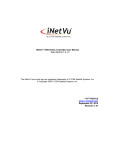
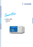
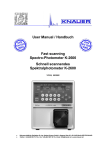
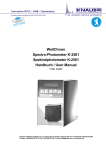
Detector UVD 2.1L User Manual V6831 HPLC 3 Table of Contents Table of Contents Note For your own safety, read the manual and always observe the warnings and safety information on the device and in the manual! Intended Use . . . . . . . . . . . . . . . . . . . . . . . . . . . . . . . . . . . . . . . . . . . . . . . 6 Device Overview . . . . . . . . . . . . . . . . . . . . . . . . . . . . . . . . . . . . . . . . . . . . . . . . 6 Operating Range . . . . . . . . . . . . . . . . . . . . . . . . . . . . . . . . . . . . . . . . . . . . . . . . 7 Features . . . . . . . . . . . . . . . . . . . . . . . . . . . . . . . . . . . . . . . . . . . . . . . . . . . . . . 7 Meaning of the LEDs . . . . . . . . . . . . . . . . . . . . . . . . . . . . . . . . . . . . . . . . . . . . . 8 Eluents . . . . . . . . . . . . . . . . . . . . . . . . . . . . . . . . . . . . . . . . . . . . . . . . . . . . . . . 9 Scope of Delivery . . . . . . . . . . . . . . . . . . . . . . . . . . . . . . . . . . . . . . . . . . . 10 Safety . . . . . . . . . . . . . . . . . . . . . . . . . . . . . . . . . . . . . . . . . . . . . . . . . . . . 11 Signal Words . . . . . . . . . . . . . . . . . . . . . . . . . . . . . . . . . . . . . . . . . . . . . . . . . . 12 Decontamination . . . . . . . . . . . . . . . . . . . . . . . . . . . . . . . . . . . . . . . . . . . . . . 12 Symbols and Signs . . . . . . . . . . . . . . . . . . . . . . . . . . . . . . . . . . . . . . . . . . 13 Unpacking and Setup . . . . . . . . . . . . . . . . . . . . . . . . . . . . . . . . . . . . . . . 14 Contacting the Technical Support . . . . . . . . . . . . . . . . . . . . . . . . . . . . . . . . . . 14 Location Requirements . . . . . . . . . . . . . . . . . . . . . . . . . . . . . . . . . . . . . . . . . . 14 Ventilation . . . . . . . . . . . . . . . . . . . . . . . . . . . . . . . . . . . . . . . . . . . . . . . . . 14 Space Requirements . . . . . . . . . . . . . . . . . . . . . . . . . . . . . . . . . . . . . . . . . . 14 Unpacking . . . . . . . . . . . . . . . . . . . . . . . . . . . . . . . . . . . . . . . . . . . . . . . . . . . . 15 Power Supply and Connection . . . . . . . . . . . . . . . . . . . . . . . . . . . . . . . . . . . . 15 Power Cable . . . . . . . . . . . . . . . . . . . . . . . . . . . . . . . . . . . . . . . . . . . . . . . . 15 Power Plug . . . . . . . . . . . . . . . . . . . . . . . . . . . . . . . . . . . . . . . . . . . . . . . . . 16 Connectors on the Rear Side . . . . . . . . . . . . . . . . . . . . . . . . . . . . . . . . . . . . . . 16 Controlling with the Pin Header . . . . . . . . . . . . . . . . . . . . . . . . . . . . . . . . . 17 Pin header Assignments . . . . . . . . . . . . . . . . . . . . . . . . . . . . . . . . . . . . . . . 17 Analog Control . . . . . . . . . . . . . . . . . . . . . . . . . . . . . . . . . . . . . . . . . . . . . . 18 Integrator Connector . . . . . . . . . . . . . . . . . . . . . . . . . . . . . . . . . . . . . . . . . 18 Initial Startup . . . . . . . . . . . . . . . . . . . . . . . . . . . . . . . . . . . . . . . . . . . . . . 19 Checklist before Initial Operation . . . . . . . . . . . . . . . . . . . . . . . . . . . . . . . . . . 19 Inserting the Flow Cell . . . . . . . . . . . . . . . . . . . . . . . . . . . . . . . . . . . . . . . . . . . 19 Setting the Optical Path Length of a Preparative Flow Cell . . . . . . . . . . . . . 20 Connecting the Capillaries . . . . . . . . . . . . . . . . . . . . . . . . . . . . . . . . . . . . . . . 20 Connecting the Leak Management . . . . . . . . . . . . . . . . . . . . . . . . . . . . . . . . . 21 Connecting a Device in a Local Area Network (LAN) to a Computer . . . . . . . . 23 Configuring the LAN Settings . . . . . . . . . . . . . . . . . . . . . . . . . . . . . . . . . . . 23 Connecting the Cables . . . . . . . . . . . . . . . . . . . . . . . . . . . . . . . . . . . . . . . . 23 Configuring the Router . . . . . . . . . . . . . . . . . . . . . . . . . . . . . . . . . . . . . . . . 24 Integrating the LAN into a Company Network . . . . . . . . . . . . . . . . . . . . . . 24 Controlling Several Systems Separately in a LAN . . . . . . . . . . . . . . . . . . . . . 25 KNAUER UVD 2.1L User Manual V6831, Version 2.1 4 Table of Contents Switching the Detector On . . . . . . . . . . . . . . . . . . . . . . . . . . . . . . . . . . . . . . . 25 Operation . . . . . . . . . . . . . . . . . . . . . . . . . . . . . . . . . . . . . . . . . . . . . . . . . 26 Control with Chromatography Software . . . . . . . . . . . . . . . . . . . . . . . . . . . . . 26 Control with Mobile Control . . . . . . . . . . . . . . . . . . . . . . . . . . . . . . . . . . . . . . 26 Control with Control Unit . . . . . . . . . . . . . . . . . . . . . . . . . . . . . . . . . . . . . . . . 26 Setting the Wavelength . . . . . . . . . . . . . . . . . . . . . . . . . . . . . . . . . . . . . . . . . . 26 Resetting the Device . . . . . . . . . . . . . . . . . . . . . . . . . . . . . . . . . . . . . . . . . . . . 27 Functionality Tests . . . . . . . . . . . . . . . . . . . . . . . . . . . . . . . . . . . . . . . . . . 27 Troubleshooting . . . . . . . . . . . . . . . . . . . . . . . . . . . . . . . . . . . . . . . . . . . 28 Possible Problems and Rectifications . . . . . . . . . . . . . . . . . . . . . . . . . . . . . . . . 28 Possible LAN Connection Problems . . . . . . . . . . . . . . . . . . . . . . . . . . . . . . . . . 30 System Messages . . . . . . . . . . . . . . . . . . . . . . . . . . . . . . . . . . . . . . . . . . . . . . 30 Maintenance and Care. . . . . . . . . . . . . . . . . . . . . . . . . . . . . . . . . . . . . . . 34 Contacting the Technical Support . . . . . . . . . . . . . . . . . . . . . . . . . . . . . . . . . . 34 Maintenance Contract . . . . . . . . . . . . . . . . . . . . . . . . . . . . . . . . . . . . . . . . . . . 35 Cleaning and Caring for the Device . . . . . . . . . . . . . . . . . . . . . . . . . . . . . . . . . 35 Cleaning the Flow Cell . . . . . . . . . . . . . . . . . . . . . . . . . . . . . . . . . . . . . . . . . . 35 Rinsing the Flow Cell . . . . . . . . . . . . . . . . . . . . . . . . . . . . . . . . . . . . . . . . . 35 Cleaning the Lens of an Analytical Flow Cell . . . . . . . . . . . . . . . . . . . . . . . . 36 Cleaning the Light Guide of a Preparative Flow Cell . . . . . . . . . . . . . . . . . . 37 Replacing the Flow Cell . . . . . . . . . . . . . . . . . . . . . . . . . . . . . . . . . . . . . . . . . . 38 Replacing the Fiber Optics . . . . . . . . . . . . . . . . . . . . . . . . . . . . . . . . . . . . . . . . 38 Removing the Fiber Optics . . . . . . . . . . . . . . . . . . . . . . . . . . . . . . . . . . . . . 38 Storage. . . . . . . . . . . . . . . . . . . . . . . . . . . . . . . . . . . . . . . . . . . . . . . . . . . 39 Technical Data . . . . . . . . . . . . . . . . . . . . . . . . . . . . . . . . . . . . . . . . . . . . . 39 Accessories and Spare Parts. . . . . . . . . . . . . . . . . . . . . . . . . . . . . . . . . . . 41 Devices and Accessories . . . . . . . . . . . . . . . . . . . . . . . . . . . . . . . . . . . . . . . . . 41 Fiber Optic Connectors . . . . . . . . . . . . . . . . . . . . . . . . . . . . . . . . . . . . . . . . 41 Available Flow Cells . . . . . . . . . . . . . . . . . . . . . . . . . . . . . . . . . . . . . . . . . . . . . 41 Preparative Flow Cells . . . . . . . . . . . . . . . . . . . . . . . . . . . . . . . . . . . . . . . . . 42 Fiber Optics Preparative Flow Cells . . . . . . . . . . . . . . . . . . . . . . . . . . . . . . . 43 Test Cells . . . . . . . . . . . . . . . . . . . . . . . . . . . . . . . . . . . . . . . . . . . . . . . . . . 44 Disposal . . . . . . . . . . . . . . . . . . . . . . . . . . . . . . . . . . . . . . . . . . . . . . . . . . 45 Legal Information . . . . . . . . . . . . . . . . . . . . . . . . . . . . . . . . . . . . . . . . . . 45 Warranty Conditions . . . . . . . . . . . . . . . . . . . . . . . . . . . . . . . . . . . . . . . . . . . . 45 Transport Damage . . . . . . . . . . . . . . . . . . . . . . . . . . . . . . . . . . . . . . . . . . . . . 46 Abbreviations and Terminology . . . . . . . . . . . . . . . . . . . . . . . . . . . . . . . 46 Index . . . . . . . . . . . . . . . . . . . . . . . . . . . . . . . . . . . . . . . . . . . . . . . . . . . . 47 Declaration of Conformity. . . . . . . . . . . . . . . . . . . . . . . . . . . . . . . . . . . . 49 KNAUER UVD 2.1L User Manual V6831, Version 2.1 5 To whom it may concern Table of Contents In case you prefer a French language user manual for this product, submit your request including the corresponding serial number via email or fax to KNAUER: [email protected] +49 30 8015010 Thank you. A qui que ce soit Si jamais vous préfériez un manuel en francais pour ce poduit contacter KNAUER par email ou par fax avec le no. de série: [email protected] +49 30 8015010 Merci beaucoup. KNAUER UVD 2.1L User Manual V6831, Version 2.1 6 Intended Use Intended Use Note: Only use the device for applications that fall within the range of the intended use. Otherwise, the protective and safety equipment of the device could fail. Device Overview Detector UVD 2.1L The UV/VIS detector is a variable single wavelength detector, designed for measuring quickly and precisely in the ultraviolet and visual spectral range. Legend 1 Status LED 1 2 Flow cell 2 3 3 Capillary guide Fig. 1 Detector UVD 2.1L front view Legend 1 Serial number 2 Integrator Output 3 LAN port 4 RS-232 port, only for servicing 5 Pin header 6 Fan 1 2 7 Connection and power switch Fig. 2 6 3 4 5 7 Detector UVD 2.1L rear view Legend 1 Left LED 2 Center LED 3 Right LED 4 Standby 1 2 3 Fig. 3 KNAUER 4 LEDs and standby on the front of the device UVD 2.1L User Manual V6831, Version 2.1 7 Intended Use Legend 1 USB port for 1 Control Unit Fig. 4 USB port for Control Unit Legend 1 Mobile Control Unit 1 Fig. 5 Optional accessory: Control Unit Operating Range The detector can be used in analytical and preparative HPLC systems. It is used in laboratories to analyze substance mixtures. In an HPLC system, the detector serves to detect substances in liquids and show their concentration. The device can be used in the following areas: Biochemistry analysis Chemical analysis Food analysis Pharmaceutical analysis Environmental analysis The detector is, e. g., used at universities, research institutions and routine laboratories. Features The deuterium lamp measures spectra from 190 nm to 750 nm Flexible use in the entire range of HPLC applications: Analytical flow cells with flow rates of 100 μl/min to preparative flow cells with 10 l/min Automatic recording and storage of the device-specific characteristics that are important for GLP (Good Laboratory Practice) the comprehensive function test (OQ: Operation Qualification) or for repairing the device KNAUER UVD 2.1L User Manual V6831, Version 2.1 8 Intended Use Automatic and current diagnosis of the device Control with chromatography software or optional Control Unit Easy integration of the detector into complex chromatography systems Integrated leak management drains liquids from leaks. Options Various types of flow cells are available to the user. Pay attention to the compatibility of the flow cells. Note: A test cell is preassembled to the detector. Before the detector can be used for measurements the test cell has to be replaced by a flow cell. The UVD 2.1L Fiber Optics Version is delivered without a test cell. Meaning of the LEDs There are three LEDs and a standby key on the front of the device. Legend 1 Left LED 2 Center LED 3 Right LED 4 Standby key 1 2 3 Fig. 6 4 LEDs and standby key on the front of the device The LEDs can have different colors depending on the operating conditions. Standby To activate the standby, keep the standby key pressed for 5 seconds. Note: Malfunctioning system after repeated standby possible. After repeatedly using the standby, switch off the power switch and back on again, to reset the data storage. Left LED Color Operating condition Operation Red Error message Check the system Shortly press the standby key to deactivate the error message Center LED KNAUER Does not light Device is switched off Switch on the device UVD 2.1L User Manual V6831, Version 2.1 9 Right LED Intended Use Color Operating condition Operation Flashes green Device not yet ready for measuring Wait until the device is ready Green Device is switched on Green Device active or ready for measuring Blue Device in standby Press the standby key to end the standby Eluents Even small quantities of other substances, such as additives, modifiers, or salts can influence the durability of the materials. If there is any doubt, contact the Technical Support of the manufacturer. Suitable solvents Acetone at 4 °C–25 °C (39.2 °F–77.0 °F)1 Acetonitrile2 Benzene Carbon dioxide (liquid 99.999 % CO2) Chloroform Dilute acetic acid (e.g. 0.1–1 %) at 25 °C/77.0 °F Dilute ammonia solution Dilute sodium hydroxide (1 M) Ethyl acetate Ethanol Formiate buffer solution Hexane/heptane Isopropanol Methanol Phosphate buffer solutions (0.5 M) Toluol Water 1. valid for the specified temperature range 2. not recommended in combination with PEEK small parts and PEEK capillary KNAUER UVD 2.1L User Manual V6831, Version 2.1 10 Scope of Delivery Less suitable solvents Dilute phosphoric acid Dimethyl sulfoxide (DMSO) Methylene chloride1 Slightly volatile solvents Tetrahydrofuran (THF)1 1. not recommended in combination with PEEK small parts and PEEK capillaries Not suitable solvents Concentrated mineral and organic acids Concentrated bases Halogenated hydrocarbons, e.g. Freon® Perfluorinated solvents, e.g. Fluorinert® FC-75, FC-40 Perfluorinated polyether, e.g. Fomblin® Solvents containing particles Scope of Delivery Note: Only use original parts and accessories made by KNAUER or a company authorized by KNAUER. Delivery Detector with test cell1 Power cord Ship kit UVD 2.1L Accessory Kit AZURA User Manual (EN/DE) Installation Qualification Documents (EN/DE) Transport securing device (standard detector only) 1. Test cell not supplied with Fiber Optics Version KNAUER UVD 2.1L User Manual V6831, Version 2.1 11 Safety Safety Professional Group The user manual addresses persons who are qualified as chemical laboratory technicians or have completed comparable vocational training. The following knowledge is required: Fundamental knowledge of liquid chromatography Knowledge regarding substances that are suitable only to a limited extent for use in liquid chromatography Knowledge regarding the health risks of chemicals Participation during an installation of a device or a training by the company KNAUER or an authorized company. If you do not belong to this or a comparable professional group, you may not perform the work described in this user manual under any circumstances. In this case, please contact your superior. Safety Equipment When working with the device, take measures according to lab regulations and wear protective clothing: Safety glasses with side protection Protective gloves Lab coat What must be taken into account? All safety instructions in the user manual The environmental, installation, and connection specifications in the user manual National and international regulations pertaining to laboratory work Original spare parts, tools, and solvents made or recommended by KNAUER Good Laboratory Practice (GLP) Accident prevention regulations published by the accident insurance companies for laboratory work Filtration of substances under analysis Use of inline filters Once they have been used, never re-use capillaries in other areas of the HPLC system. Only use a given PEEK fitting for one specific port and never re-use it for other ports. Always install new PEEK fittings on each separate port. Follow KNAUER or manufacturer's instructions on caring for the columns More safety-relevant information is listed below: flammability: Organic solvents are highly flammable. Since capillaries can detach from their screw fittings and allow solvent to escape, it is prohibited to have any open flames near the analytical system. KNAUER UVD 2.1L User Manual V6831, Version 2.1 12 Safety solvent tray: Risk of electrical shock or short circuit if liquids get into the device's interior. For this reason, place all bottles in a solvent tray. solvent lines: Install capillaries and tubing in such a way that liquids cannot get into the interior in case of a leak. leaks: Regularly check if any system components are leaking. power cable: Defective power cables are not to be used to connect the device and the power supply system. self-ignition point: Only use eluents that have a self-ignition point higher than 150 °C under normal ambient conditions. power strip: If several devices are connected to one power strip, always consider the maximum power consumption of each device. power supply: Only connect devices to voltage sources, whose voltage equals the device's voltage. toxicity: Organic eluents are toxic above a certain concentration. Ensure that work areas are always well-ventilated! Wear protective gloves and safety glasses when working on the device! Where is use of the device prohibited? Decommissioning the Device Securely Opening the Device Never use the system in potentially explosive atmospheres without appropriate protective equipment. For further information, contact the Technical Support of KNAUER. At any time, take the device completely out of operation by either switching off the power switch or by pulling the power plug. The device may be opened by the KNAUER Technical Support or any company authorized by KNAUER only. Signal Words Possible dangers related to the device are divided into personal and material damage in this user manual. DANGER! Lethal or very serious injuries can occur. WARNING! Serious or moderate injuries can occur. CAUTION! Moderate injuries and/or device defects can occur. Decontamination Contamination of devices with toxic, infectious or radioactive substances poses a hazard for all persons during operation, repair, sale, and disposal of a device. DANGER! Health danger if getting in contact with toxic, infectious or radio-active substances. Before disposing of the device or sending it away for repair, you are required to decontaminate the device adequately. KNAUER UVD 2.1L User Manual V6831, Version 2.1 13 Symbols and Signs All contaminated devices must be properly decontaminated by a specialist company or the operating company before they can be recommissioned, repaired, sold, or disposed of. All materials or fluids used for decontamination must be collected separately and disposed of properly. Symbols and Signs The following symbols and signs can be found on the device, in the chromatography software or in the user manual: Symbol Meaning High-voltage hazard Electric shock hazard Electrostatic discharge hazard, damages to system, device, or components can occur. General warning sign, moderate injuries can occur and also damages to system, device, or components. UV-light hazard, eye injuries can occur. Leak hazard, damages to device can occur. Obey maximum load for leak tray during transportation, installation and operation. A device or system marked with CE fulfills the product specific requirements of European directives. This is confirmed in a Declaration of Conformity. Testing seals in Canada and the USA at nationally recognized testing centers (NRTL). The certified device or system has successfully passed the quality and security tests. KNAUER UVD 2.1L User Manual V6831, Version 2.1 14 Unpacking and Setup Unpacking and Setup Contacting the Technical Support You have various options to contact the Technical Support: Phone Fax E-mail +49 30 809727-111 +49 30 8015010 [email protected] You can make your requests in English and German. Location Requirements Requirements The location for the device must meet the following requirements: level surface for device or system Protect from heavy ventilation Weight 5.9 kg 6 kg (Fiber Optics Version) Dimension 361 × 158 × 523 mm (Width × Height × Depth) Power supply 100 – 240 V; 50 – 60 Hz; 75 W Humidity below 90 %, non condensing Temperature range 4 - 40 °C; 39.2 - 104 °F Ventilation CAUTION! Defect of the device due to overheating possible! Set up the device in such a way that it is protected against exposure to direct sunlight. Make sure the room is well-ventilated. Keep at least 15 cm clear at the rear and 5 – 10 cm at each side of the device for air circulation. Space Requirements Side clearance to other devices: At least 5 cm, if there is another device on one side. At least 10 cm, if there are devices set up on both sides. KNAUER UVD 2.1L User Manual V6831, Version 2.1 15 Unpacking and Setup At least 15 cm on the rear panel for the fan. Unpacking Store all packing materials. Included packing list should be kept for repeat orders. Tools Utility knife CAUTION! Damage to the device by carrying or lifting it on protruding housing parts. Lift the device on the side of the housing only. Procedure 1. Check for damages caused during transportation. In case you notice any damage, contact the Technical Support and the forwarder company. 2. Set up the delivery so the label is in the correct position. Using the utility knife, cut the adhesive tape. Open the delivery. 3. Remove the foam inserts. Take out the accessories kit and the manual. 4. Open the accessories kit and take out all accessories. Check the scope of delivery. In case any parts are missing, contact the Technical Support. 5. Grip the device at its side panels near the middle and lift it out of the packaging. 6. Remove the foam inserts from the device. 7. Check for damages caused during transportation. In case you notice any damage, contact the Technical Support. 8. Set up the device in its appropriate location. 9. Remove the protective foil and transportation securing device (standard detector only). Power Supply and Connection The device is intended for use with AC power networks of 100240 V. The supplied power cable is to be used to connect the device to the mains supply. Only use power units with a permission for use from your country. In case of queries contact the Technical Support Power Cable Only the supplied power cable is to be used to connect the device to the mains supply. Replace defective power cables only with original accessories from KNAUER. KNAUER UVD 2.1L User Manual V6831, Version 2.1 16 Unpacking and Setup Power Plug Note: Make sure that the power plug on the rear of the device is always accessible, so that the device can be disconnected from the power supply. CAUTION! Electric hazard if the device is turned on while connecting or interrupting the power connection. Switch off the device beforehand. Connectors on the Rear Side The connector for the Control Unit is on the right side and all other connectors are on the rear side of the detector. Legend 1 Serial number 2 Integrator Output 3 LAN port 4 RS-232 port (service only) 5 Pin header 6 Fan 1 2 7 Connection and power key Fig. 7 3 4 5 6 7 Detector UVD 2.1L rear view 8 USB port for Con8 trol Unit Fig. 8 USB port for Control Unit External devices like computers, fraction collectors, etc. can be connected in 2 different ways to the detector: Connected with the pin header Connected with LAN within a network KNAUER UVD 2.1L User Manual V6831, Version 2.1 17 Unpacking and Setup Controlling with the Pin Header CAUTION! Short-circuit hazard. - Turn off the device before connecting it to the multi-pin connector. - Pull the power plug. Pin header Assignments Connector Function EV 1 (Event 1) Relay contact The contact is on a floating basis. Its setting depends on the settings in the Control Unit or software. Steady-rate signal: passive = open relay contact active = closed relay contact Pulse: Closed relay contact for at least 1000 ms Permissible load of the relay contact: 1 A/ 24 V DC EV 2 (Event 2) TTL output Levels: passive 5 V active 0 V Pulse: 0 V for at least 1000 ms EV 3 (Event 3) TTL output Levels: passive 5 V active 0 V Pulse: 0 V for at least 1000 ms Error IN TTL input Low active Secure switching threshold at least 10 mA After receiving a signal (short circuit to ground) from an external device, an error message appears and the device stops. Start IN TTL input Low active Secure switching threshold at least 10 mA After receiving a signal (short circuit to ground) from an external device, the device starts. If controlled via software, an electronic trigger is sent via LAN. KNAUER UVD 2.1L User Manual V6831, Version 2.1 18 Unpacking and Setup Connector Function Autozero Low active Secure switching threshold at least 10 mA A signal (short circuit to ground) sets the measuring signal to zero. +5 V Provides a voltage of 5 V with respect to GND. This makes it possible to supply an appliance that is switched by an EVENT. Max. current: 50 mA GND Reference point of the voltage at the signal inputs. +24 V Valve Event controlled switching of 24 V against GND Max. current: 200 mA External Allows external analog control of the detector when the option ANALOG has been selected in the SETUP menu. The control voltage must be applied against AGND. Voltage range: 0-10 V The scaling can be changed by the user. AGND Reference point of the voltage at the input external l Analog Control Using the analog port, you can control the wavelength by changing the applied voltage. A Control Unit is required in order to select the option ANALOG in the SETUP menu. Example To use the analog port for controlling the detector, you have to set a zero point and enter a scaling value. Zero point at 0 V = 000 nm Scaling: 100 nm per Volt If 5 V voltage is applied, the wavelength is 500 nm. Integrator Connector The integrator connector sends measuring signals from the detector. non-bipolar 1 channel 0 to 5 V DAC 20 bit scalable adjustable to offset KNAUER UVD 2.1L User Manual V6831, Version 2.1 19 Initial Startup Initial Startup Note: Before the detector is ready to use for measurements, a flow cell must be installed. You can change the optical path length of a preparative flow cell before assembling the flow cell. The optimal path length depends on type and quantity of the sample. Checklist before Initial Operation Use this checklist to determine whether the detector is ready for initial startup: Device is in the correct location. Note: Observe the ambient conditions and space requirements! The power connection of the detector is plugged in. If the detector is part of a HPLC system, the following must be observed: The network connection to the router is established The KNAUER chromatography software OpenLAB®, ChromGate® or ClarityChrom® has been installed by KNAUER or a company authorized by KNAUER. Capillaries from the column to the UV detector and capillaries from the detector to the waste bottle are securely attached. Inserting the Flow Cell Note: The test cell is used during operation qualifications and must be stored. Prerequisite Detector has been switched off. Power plug has been pulled. Procedure Process Figure 1. Unscrew the 2 knurledhead screws 1. 2. Pull out the slide 2 as far as it needed to take out the test cell. 1 Fig. 9 Removing the slide 3. Remove the test cell. 4. Insert the flow cell 3 into the slide. 5. Push the slide 2 into the detector. 2 3 6. Insert the knurled-head screws and screw tight. Fig. 10 KNAUER Assembling the flow cell UVD 2.1L User Manual V6831, Version 2.1 20 Result Initial Startup Flow cell is assembled. The next step is connecting the capillaries. Setting the Optical Path Length of a Preparative Flow Cell Depending on type, the path length is factory set to 2 mm, 3 mm, or 10 mm. You can remove the spacers on one or both sides and hence change the path length to 1.25 mm or 0.5 mm. Legend 1 2 3 1 Threaded ring 2 Cover 3 Spacer 4 5 4 Seal holder (compression bushing) 5 Light guide with PTFE seal Fig. 11 Prerequisite Tools Preparative flow cell Flow cell has been disassembled. Allen screwdriver, size 3 WARNING! Irritation of retina through UV light! Concentrated UV light can leak out from the flow cell or the fiber optic connectors. Switch off the device and pull the power plug. Procedure 1. Using the allen screwdriver, unscrew and remove the threaded ring 1. 2. Remove the cover 2 and spacer 3. Put the spacer aside. 3. Insert the cover. 4. Using the allen screwdriver, tighten the threaded ring. Enlarging To enlarge the optical path length, put in one or both spacers. Connecting the Capillaries Capillaries connect the detector to other devices and lead liquids. Prerequisite KNAUER Flow cell has been assembled. UVD 2.1L User Manual V6831, Version 2.1 21 Initial Startup Tools Torque wrench CAUTION! Damage to the flow cell caused by strongly tightened fittings! Check the torque of screw fittings: - 5 Nm for stainless steel fittings - 0.5 Nm for PEEK fittings Note: PEEK fittings withstand a maximum pressure of 400 bar. Procedure Steps 1. Push the capillary 2 through the fitting 1. Figure 1 2 3 2. Push the clamping ring 3 onto capillary. Fig. 12 Capillary fitting 3. Manually, screw together the capillary and the flow cell 4. To avoid leaks, tighten the fitting 5 with a maximum torque of 5 Nm for stainless steel fittings or 0.5 Nm for PEEK fittings by using the open-end wrench. 4 5 Fig. 13 Result Capillary and flow cell Capillaries have been connected and the detector is ready for operation. Connecting the Leak Management The leak management consists of the leak sensor and the drainage system. The drainage system ensures that escaping liquids flow into a waste bottle. If there is too much liquid, the red LED starts flashing. Both the device and the data acquisition via chromatography software are stopped. Prerequisite KNAUER The front cover has been removed. UVD 2.1L User Manual V6831, Version 2.1 22 Procedure Initial Startup Process Figure 1. Carefully push the funnel 1 into the center opening of the capillary guide 2. 1 2 Abb. 14 Funnel and capillary guide 2. Push the long ending of the first nozzle 4 into the hose 3. 3 4 Abb. 15 Hose and nozzle 3. Connect the nozzle and the funnel. 4. Push the other end of the hose onto the nozzle 5 of the leak tray. 5 Abb. 16 Hose connected to device 5. For the bottom device, push the short end of the nozzle 6 into the opening in the collection point of the leak tray. 6. Connect the hose to the nozzle and lead the second ending to the waste bottle. 6 Abb. 17 Leak tray with nozzle 7. Place the waste bottle below the bottom device. Next steps KNAUER Attach the front cover. UVD 2.1L User Manual V6831, Version 2.1 23 Initial Startup Connecting a Device in a Local Area Network (LAN) to a Computer This section describes how to set up an HPLC system in a local area network (LAN) and how a network administrator can integrate this LAN into your company network. The description applies to the operating system Windows® and all conventional routers. Note: To set up a LAN, we recommend to use a router. That means the following steps are required: Process 1. On the computer, go to the control panel and check the LAN properties. 2. Hook up the router to the devices and the computer. 3. On the computer, configure the router to set up the network. 4. Install the chromatography software from the data storage device. 5. Switch on the device and run the chromatography software. Configuring the LAN Settings The LAN uses only one server (which is normally the router) from that the devices automatically receive their IP address. Prerequisite In Windows®, power saving, hibernation, standby, and screen saver must be deactived. In case you use an USB-to-COM box, the option "Allow the computer to turn off ths device to save power" in the devicemanager must be deactivated for all USB hosts. Only for Windows 7: For the network adapter, the option "Allow the computer to turn off this device to save power" in the Device Manager must be deactivated. Procedure 1. In Windows 7 choose Start Control Panel Network and Sharing Center. 2. Double-click on LAN Connection. 3. Click on the button Properties. 4. Select Internet Protocol version 4 (TCP/IPv4). 5. Click on the button Properties. 6. Check the settings in the tab General. The correct settings for the DHCP client are: a) Obtain IP address automatically b) Obtain DNS server address automatically 7. Click on the button OK. Connecting the Cables A router 3 has several LAN ports 2 and one WAN port 4 that can be used to integrate the LAN into a wide area network (WAN), e.g. a company network or the Internet. In contrast, the KNAUER UVD 2.1L User Manual V6831, Version 2.1 24 Initial Startup LAN ports serve to set up a network from devices 1 and a computer 5. To avoid interference, we recommend operating the HPLC system separately from the company network. 1 2 3 4 5 You will find patch cables for each device and the router in the accessories kit. To connect the router to a WAN, an additional patch cable is required, which is not supplied within the scope of delivery. Prerequisite The computer has been switched off. There is a patch cable for each device and the computer. Procedure 1. Use the patch cable to connect the router and the computer. Repeat this step to connect all devices. 2. Use the power supply to connect the router to the mains power system. Configuring the Router The router is preset at the factory. You will find a label at the bottom side of the router, on which IP address, user name, and password are printed. These information help to open the router configuration. Procedure 1. To open the router configuration, start your Internet browser and enter the IP address (not for all routers). 2. Enter user name and password. 3. Configure the router as DHCP server. 4. In the router configuration, check the IP address range and make changes if necessary. Result Once the router has assigned IP addresses to all devices, the chromatography software can be used to remotely control the system. Integrating the LAN into a Company Network A network administrator can integrate the LAN into your company network. In this case you use the WAN port of the router. Prerequisite Procedure KNAUER There is a patch cable for the connection. 1. Check that the IP address range of the router and of the company network do not overlap. UVD 2.1L User Manual V6831, Version 2.1 25 Initial Startup 2. In case of an overlap, change the IP address range of the router. 3. Use the patch cable to connect the router WAN port to the company network. 4. Restart all devices, including the computer. Controlling Several Systems Separately in a LAN Devices connected to a LAN communicate through ports, which are part of the IP address. If more than one HPLC system is connected to the same LAN and you plan on controlling them separately, you can use different ports to avoid interference. Therefore, the port number for each device must be changed and this same number must be entered into the device configuration of the chromatography software. We recommend to use the same port number for all devices in the same system. Note: The port is set to 10001 at the factory. You must use the same numbers in the device configuration of the chromatography software as in the device, otherwise the connection fails. Procedure 1. Find out port number and change it on the device. 2. Enter the port number in the chromatography software. Result The connection is established. Switching the Detector On The device is switched on by the power key on the back of the device. Prerequisite Installation has been completed. Flow cell has been assembled. CAUTION! Possible damage to the device caused by condensed water! Allow device to acclimate for 3 h, before it is connected to power supply and taken into operation. . Procedure Process Figure 1. Insert the plug into the female connector 2 at the rear panel. 1 2 2. Plug the other end into an electric socket. 3. Switch on the device at the power key 1 . KNAUER Fig. 18 Power key with female connector at the rear panel UVD 2.1L User Manual V6831, Version 2.1 26 Result Practical tip Operation The detector starts its self calibration. The display shows the progress that has been made. When the self calibration has finished, the status display appears. If the self calibration fails, switch the detector off and back on again. Regularly check the capillaries for leaks. Operation A device can be operated in several ways: with chromatography software with Control Unit with Mobile Control Note: It is not possible to use two operating methods simultaneously. If the device is connected to the software, it cannot be controlled via Control Unit or Mobile Control. The device status can however be monitored. Control with Chromatography Software To control the device with chromatography software, it must be connected to the computer through the LAN interface. AZURA Devices can be controlled with e. g. OpenLAB EZChrom edition version A.04.05 or higher, ChromGate version 3.3.2 or higher and ClarityChrom version 3.0.7 or higher and PurityChrom version 5.07.039 or higher. You will find a detailed description on the chromatography software in the software manual. Control with Mobile Control The Mobile Control is an app which can be installed on your computer or tablet. To control the device using the Mobile Control, connect the computer or tablet to a wireless LAN router. Data transfer between device and app is actualized through wireless LAN. You find a detailed description on the Mobile Control in its accompanying user manual. Control with Control Unit You can control the device using the touchscreen on the mobile Control Unit. The Control Unit is an optional accessory. You will find a detailed description on the Control Unit in its accompanying user manual. Setting the Wavelength You can set a wavelength between 190 – 750 nm. KNAUER UVD 2.1L User Manual V6831, Version 2.1 27 Functionality Tests Resetting the Device Using the Control Unit or Mobile Control, you can re-set the detector to its default settings. Parameter Setting Network LAN DHCP, port 10001 Lamps D2 ON Time constant 2s Channels Channel 1: WL = 254 nm Analog out Offset 1 = 10 mV, Scale 1 = 1 AU/V Event check All events deactivated (o) Date/Time Current date/time Fraction collector OFF Leak sensor ON, Sensitivity = low Functionality Tests Installation Qualification (IQ) The customer may request the Installation Qualification, which is free of charge. In case of a request, the Technical Support of KNAUER or from a provider authorized by KNAUER performs this functionality test during the installation. The Installation Qualification is a standardized document that comes as part of the delivery and includes the following: confirmation of flawless condition at delivery check if the delivery is complete certification on the functionality of the device Operation Qualification (OQ) The Operation Qualification includes an extensive functionality test and must be purchased from the manufacturer. Contact the KNAUER Sales Department to request an offer. The Operation Qualification is a standardized KNAUER document and includes the following: definition of customer requirements and acceptance terms documentation on device specifications device functionality check at installation site Test Intervals To make sure that the device operates within the specified range, you should test the device using the Operation Qualification at following intervals: Every 3 months: average useful life of more than 5 days/week or 24 hours/day; when operating with buffer solutions or other salt solutions: KNAUER UVD 2.1L User Manual V6831, Version 2.1 28 Troubleshooting Every 6 months: average useful life of 1 to 5 days/week Execution The test can be carried out either by the Technical Support of KNAUER or from a provider authorized by KNAUER. Troubleshooting First measures 1. Check all cabling. 2. Check all screw fittings. 3. Check whether air has entered into the supply lines. 4. Check device for leaks. 5. Check system messages in the Control Unit or software. Possible Problems and Rectifications Problem Solution Baseline drift Maintain constant temperature conditions during the measurement. Device will not turn on Inspect the power cable to ensure that it is plugged into the power supply. Device cannot be calibrated 1. Fasten the knurled-head screws on the slide to prevent incursion from interfering light or an electronics error. 2. Insert the test cell. 3. Inspect the calibration with a weak absorbing eluent. Baseline noise 1. Inspect the flow cell assembly. 2. Fasten the knurled-head screws on the slide to prevent incursion from interfering light or an electronics error. 3. Exchange the defective flow cell. 4. Inspect the service life of the lamp on the display. 5. Reduce the air in the flow cell by using a degasser. The relationship of the signal to the light path reference is very low Further measures 1. Flush the flow cell. 2. Clean the flow cell window. 3. Replace the lamps 1. Install the maintenance software (service tool). 2. Save device information and send to manufacturer. KNAUER UVD 2.1L User Manual V6831, Version 2.1 29 Troubleshooting 3. Inform the Technical Support of the manufacturer. KNAUER UVD 2.1L User Manual V6831, Version 2.1 30 Troubleshooting Possible LAN Connection Problems Go through the following steps, in case no connection between the computer and the devices can be established. Check after each step if the problem is solved. If the problem cannot be located, call the Technical Support. 1. Check the status of the LAN connection in the Windows task bar: Connected Connection not established If no connection was established, test the following: Is the router switched on? Is the patch cable connected correctly to the router and the computer? 2. Check the router settings: Is the router set to DCHP server? Is the IP address range sufficient for all the connected devices? 3. Check all connections: Are the patch cable connected to the LAN ports and not the WAN port? Are all cable connections between devices and router correct? Are the cables plugged in tightly? 4. If the router is integrated into a company network, pull out the patch cable from the WAN port. Can the devices communicate with the computer, even though the router is disconnected from the company network? 5. In case you own a Control Unit, check the settings in the menu Setup > Network. Is LAN-DHCP set for controlling? Did the device receive an IP address? 6. Turn off all devices, router, and computer. Firstly, turn on the router and secondly turn on the devices and the computer. Has this been successful? 7. Replace the patch cable to the device with that no connection could be established. Has this been successful? 8. Make sure that the IP port of the device matches the port in the chromatography software. System Messages If other system messages are displayed besides those listed below, please turn the device off and then on. Inform the Technical Support of the manufacturer in case the system message repeats itself. KNAUER UVD 2.1L User Manual V6831, Version 2.1 31 Troubleshooting The system messages are in alphabetical order: C KNAUER System message Solution Calibration failed Restart the device. Check whether lamps, motor and filter are functioning correctly. Inform the Technical Support of the manufacturer in case the system message repeats itself. Restart calibration on the device or in the chromatography software. Calibration failed Filter position error The filter wheel moves incorrectly. Restart the device. Inform the Technical Support of the manufacturer in case the system message repeats itself. Calibration failed Low light Both reference channel and signal channel do not have enough light for the calibration due to, for instance, a defective lamp. Restart the device. Inform the Technical Support of the manufacturer in case the system message repeats itself. Calibration failed: Signal path open Restart the device. Inform the Technical Support of the manufacturer in case the system message repeats itself. Calibration failed: Too much light Restart the device. Inform the Technical Support of the manufacturer in case the system message repeats itself. Cannot delete active program/link First pause link, then delete program. Cannot edit program from the running link First pause link, then edit data using chromatography software. Cannot initialize LAN Check cables and connections in local area network. Cannot operate an uncalibrated instrument Restart the device. Wait until calibration is completed. Cannot operate with an empty link Create a link. Cannot proceed: D2 lamp heating Restart the device. If the error occurs again, replace the lamp. Cannot proceed: D2 lamp is OFF! Switch the lamp on. If the error occurs again, restart the device. If the lamp is off after restarting, replace the lamp. UVD 2.1L User Manual V6831, Version 2.1 32 Troubleshooting System message Solution Cannot proceed: lamps are off. Switch the lamp on. If the error occurs again, restart the device. If the lamp is off after restarting, replace the lamp. Cannot read data from FRAM Restart the device. Inform the Technical Support of the manufacturer in case the system message repeats itself. Cannot read RTC Restart the device. Inform the Technical Support of the manufacturer in case the system message repeats itself. Cannot write data on FRAM Delete the programs. D2 lamp operation failed Restart the device. If the error occurs again, replace the lamp. D2 lamp does not start Restart the lamp. Inform the Technical Support of the manufacturer in case the system message repeats itself. The lamp unit has to be replaced. Data acquisition active No entries are possible. First stop acquiring measurement data, afterwards you can make a new entry. F Filter move error Restart the device. Inform the Technical Support of the manufacturer in case the system message repeats itself. G GUI communication failed Restart the device. Inform the Technical Support of the manufacturer in case the system message repeats itself. Instrument remote controlled This entry is not executable. Close and exit the software. Invalid command Check the cable connections. Change the entry. Invalid line number Change the entry in the program line. Invalid link Reconfigure the link. Invalid parameter(s) Check the validity of the parameters. Invalid time in time table Correct the time entry. Invalid index in time table Change the entry in the program line. D I KNAUER UVD 2.1L User Manual V6831, Version 2.1 33 Troubleshooting System message Solution Leak sensor not present Switch the device off and then on. If the leak sensor is still not present, contact the Technical Support of the manufacturer. Leak was detected Switch off the device. Remove the leak and start the device afterwards. Link does not exist Create a link. Link is running Wait until the link has been completed, then change the link or delete it. Motor end position reached Instrument will be recalibrated The motor that controls the wavelength reached its end position and stopped. Recalibrate the device. Inform the Technical Support of the manufacturer in case the system message repeats itself. Motor failure Restart the device. Inform the Technical Support of the manufacturer in case the system message repeats itself. No link available Create a link. Not enough space to store link Check the number of link lines. A maximum of 50 link lines are possible. Not enough space to store program Check the number of program lines. A maximum of 50 program lines are possible. O Operation time out Restart the device. Inform the Technical Support of the manufacturer in case the system message repeats itself. P Program does not exist Create a program. Program is running Quit program or wait until program has been completed. This link is used in WAKEUP First quit or delete wakeup program (wu = Wake Up), then edit or delete link. This program is used in a link First pause or delete the link, then edit or delete data by means of the chromatography software. This program is used in WAKEUP First quit or delete wakeup program (wu = Wake Up), then edit or delete data by means of the chromatography software. L M N T KNAUER UVD 2.1L User Manual V6831, Version 2.1 34 W Maintenance and Care System message Solution Time already exists Correct the time entry. Too many lines in program Check the number of program lines. A maximum of 50 program lines are possible. Wake up time already passed! Specify new time. Maintenance and Care Organic solvents are toxic above a certain concentration. Ensure that work areas are always well-ventilated! When performing maintenance tasks on the device, always wear safety glasses with side protection, protective gloves, and an overall. All wetter components of a device, e. g. flow cells of detectors or pump heads and pressure sensors for pumps, have to be flushed with isopropanol first and water afterwards before being maintained, disassembled or disposed. WARNING! Irritation of retina through UV light! Concentrated UV light can leak out from the flow cell or the fiber optic connectors. Switch off the device and pull the power plug. CAUTION! Performing maintenance tasks on a switched on device can cause damage to the device. Switch off the device and pull the power plug. Users may perform the following maintenance tasks themselves: Regularly check the light intensity of the D2 lamp (best before 2000 operating hours). Inspect the flow-cell assembly Clean the flow cell. Replace the flow cell. Proper maintenance of your HPLC device will ensure successful analyses and reproducible results. Contacting the Technical Support You have various options to contact the Technical Support: Phone Fax E-mail KNAUER +49 30 809727-111 +49 30 8015010 [email protected] UVD 2.1L User Manual V6831, Version 2.1 35 Maintenance and Care You can make your requests in English and German. Maintenance Contract The following maintenance work on the device may only be performed by the manufacturer or a company authorized by the manufacturer and is covered by a separate maintenance contract: Opening the device Removing the hood or the side panels. Cleaning and Caring for the Device CAUTION! Intruding liquids can cause damage to the device. - Place solvent bottles next to the device or in a solvent tray. - Moisten the cleaning cloth only slightly. All smooth surfaces of the device can be cleaned with a mild, commercially available cleaning solution, or with isopropanol. Cleaning the Flow Cell Increased baseline noise and reduced sensitivity can be a result of a dirty flow cell. Often it is sufficient to rinse the flow cell to restore optimal sensitivity. Note: Dirty lenses or fiber optic connectors could falsify the measurement. Do not touch the lens or the fiber optic connector lends with bare hands. Wear gloves. Rinsing the Flow Cell The following solvents are recommended for rinsing: diluted HCl (1 mol/L) 1 ml/L NaOH aq. Ethanol Acetone Tools Syringe CAUTION! Contamination of the flow cell caused by oil drops! - Do not use compressed air for drying. Procedure 1. Fill the syringe with eluent. 2. Inject it into the inlet of the flow cell and allow it to act for 5 minutes. 3. Fill the syringe with water and inject again. KNAUER UVD 2.1L User Manual V6831, Version 2.1 36 Maintenance and Care 4. Remove the flow cell from the detector and use a nitrogen stream to dry it. Result Next steps Flow cell is clean. Check if the baseline noise has improved. If the rinsing does not have the desired effect, all flow cells can be disassembled to clean the lens. Cleaning the Lens of an Analytical Flow Cell Legend 1 Seal ring 2 Lens 3 Compression part 4 Threaded ring 1 2 3 4 Fig. 19 Prerequisite Analytical flow cell Device has been switched off. Power plug has been pulled. Flow cell has been removed. Tools Tweezers Allen screwdriver, size 3 Procedure 1. Using the allen screwdriver, loosen the threaded ring 4. 2. Using tweezers or by gently tapping on a clean surface, remove the compression part 3. 3. The lens 2 is protected by a seal ring 1. This must be renewed every time the lens is disassembled. 4. Remove the lens and clean with a clean, soft cloth or with water in an ultrasonic bath. 5. Afterwards, assemble the flow cell and make sure that the new seal ring does not interrupt the light path. 6. Using the allen screwdriver, tighten the threaded ring. Result What to do when... KNAUER Flow cell can be assembled. If the cleaning of the lens does not have the desired effect, the lens has to be replaced. UVD 2.1L User Manual V6831, Version 2.1 37 Maintenance and Care Cleaning the Light Guide of a Preparative Flow Cell The preparative flow cells have a rod shaped light guide instead of the concave lens of the analytical cells. Legend 1 2 3 1 Threaded ring 2 Cover 3 Spacer 4 4 Compression bush- 5 ing 5 Light guide with seal ring Seal Fig. 20 Prerequisite Preparative flow cell Device has been switched off. Power plug has been pulled. Flow cell has been removed. Tools Tweezers Allen screwdriver, size 3 Procedure 1. Using the screwdriver, loosen the threaded ring 1. 2. Remove the cover 2 and the spacer 3 (not part of all flow cells). 3. Using the tweezers, pull out the compression bushing 4 and the light guide 5. 4. Carefully push the light guide out of the holder and strip off the seal. The seal ring needs to be renewed during every cleaning of the fiber optics. 5. Clean the light guide with a clean, soft cloth or with an appropriate solvent in an ultrasonic bath. Make sure that the clean light guide is not touched by fingers. 6. Afterwards, assemble the flow cell and make sure that the new seal ring does not interrupt the light path. 7. Using the screwdriver, tighten the threaded ring 1. Result What to do when... KNAUER Flow cell can be assembled. If the cleaning does not have the desired effect, the light guide has to be replaced. UVD 2.1L User Manual V6831, Version 2.1 38 Maintenance and Care Replacing the Flow Cell UV light will cause the flow cells to become blind with time (solarization), making them no longer suitable for use. Prerequisite Detector has been switched off. Power plug has been pulled. Capillaries are disconnected. Procedure Steps Figure 1. Unscrew the knurled-head screws 1. 1 2. Pull out the slide 2. 3. Remove the flow cell. Fig. 21 Removing the slide 4. Insert the flow cell 3 into the slide. 5. Push the slide into the detector 2. 6. Insert the knurledhead screws and screw tight. Result 2 3 Fig. 22 Assembling the flow cell Flow cell is assembled. The next step is to connect the capillaries. Replacing the Fiber Optics UV light will cause the fiber optics to become blind with time (solarization), making them no longer suitable for use. Observe the following regarding the use of fiber optics: Do not touch the ends of the fiber optics with your fingers, as this could falsify the measurement. Handle the fiber optics with care, avoid impacts or hard actions. Move the fiber optics carefully without using pressure or bending it. Removing the Fiber Optics Prerequisites Tools The device has been switched off. Cap fittings for the fiber optics Note: Do not touch the ends of the fiber optics with your fingers, as this could falsify the measurement. KNAUER UVD 2.1L User Manual V6831, Version 2.1 39 Procedure Storage Process Figure 1. Manually, unscrew the fittings 1 of the fiber optics from the flow cell. 1 Fig. 23 2. Seal the fiber optic connectors with caps 2. Fiber optics fittings on the flow cell 2 Fig. 24 3. Manually, unscrew the fiber optics 3 from the detector. Cap fittings on the fiber optics 3 Fig. 25 Fiber optic connectors on the detector Storage The device can be stored within the following ambient conditions: Temperature range: 4–40 °C; 39.2–104 °F Air humidity: Below 90 % humidity (non condensing) Technical Data Detection KNAUER Detector type Variable single wavelength UV/VIS detector Variable single wavelength UV/VIS detector with fiber optic connectors Detection channels 1 Light source Deuterium (D2) lamp with integrated GLP chip Wavelength range 190 – 750 nm Spectral bandwidth 11 nm at H line (FWHM) UVD 2.1L User Manual V6831, Version 2.1 40 Communication Technical parameters Ambient conditions General KNAUER Technical Data Wavelength accuracy ± 2.5 nm Wavelength precision 0.3 nm (ASTM E275-93) Noise ± 1.5 × 10⁻⁵ AU at 254 nm ± 2.0 x 10⁻⁵ AU at 254 nm (fiber optics version) (ASTM E1657-98) Drift 3.0 × 10⁻⁴ AU/h at 254 nm 4.0 x 10⁻⁴ AU/h at 254 nm (fiber optics version) (ASTM E1657-98) Linearity > 2.0 AU at 270 nm (ASTM E1657-98) Time constants 0.0/0.1/0.2/0.5/1.0/2.0/5.0/10.0 s Integration time Automatic Maximum data rate 50 Hz (LAN), 20 Hz (Analog) Inputs Error (IN), Start (IN), Autozero, 0 – 10 V Analog IN Outputs Events 1-3, + 5 V, 24 V Value Analog outputs 1 × 0 – 5 V scalable, 20 bit, offset adjustable Control Digital: LAN-DHCP, remote connector Analog: wavelength control Manual: Control Unit (Optional) Programming Timed: wavelength, events, fraction valve, links; wake-up (program, link); 9 programs, 50 program lines GLP Detailed report including lamp recognition, operating hours, lamp operating hours, number of lamp ignitions Display Control Unit (Optional) Temperature range 4 – 40 °C, 39.2 – 104 °F Air humidity below 90 %, non condensing Power supply 100 – 240 V; 50 – 60 Hz; 75 W Dimensions 361 × 158 × 523 mm (W × H × D) Weight 5.9 kg 6.0 kg (fiber optics version) Leak sensor Yes Protection type IP 20 UVD 2.1L User Manual V6831, Version 2.1 41 Accessories and Spare Parts Height above sea level maximum 2000 meters Accessories and Spare Parts Note: For repeat orders of spare parts use the enclosed packing list. Contact the Technical Support in case there are any questions on spare parts or accessories. Devices and Accessories Name Order number AZURA UV/VIS Detector UVD 2.1L without flow cell ADA01XA AZURA UV/VIS Detector UVD 2.1L Fiber Optics Version without flow cell ADA04XA Control Unit AZD00 Tool kit AZURA A1033 Repair kit for analytical flow cells A1131 Repair kit for preparative flow cells A1132 Deuterium lamp A5193 Accessories kit FDA AZURA accessories kit FZA02 German user manual English user manual V6831 V6831A Fiber Optic Connectors Name Order number 2 × fiber optic connector 750 mm A0740 1 × fiber optic connector 750 mm A0742 2 × fiber optic connector, custom made size A0743 1 × fiber optic connector 400 mm A0911 Fiber optic coupling A4530 Available Flow Cells Most flow cells are also available equipped with fiber optic connectors for the use with the fiber optics version of the detector. KNAUER UVD 2.1L User Manual V6831, Version 2.1 42 Accessories and Spare Parts Analytical Flow Cells Technical data Path length Connection Inner diameter Volume Material Order number 10 mm 1/16“ 1.1 mm 10 μl Stainless steel with heat exchanger 20 ml/min 300 bar A4061XB A4061 A4074 (fiber optics version) Max. flow rate Max. pressure 10 mm 1/16“ 1.1 mm 10 μl Stainless steel with heat exchanger 20 ml/min 300 bar Path length Connection Inner diameter Volume Material Max. flow rate Max. pressure 3 mm 1/16“ 1.0 mm 2 μl Stainless steel 50 ml/min 300 bar A4042 A4044 (fiber optics version) Path length Connection Inner diameter Volume Material Max. flow rate Max. pressure 3 mm 1/16“ 1.0 mm 2 μl PEEK 50 ml/min 30 bar A4045 A4047 (fiber optics version) Max. flow rate Max. pressure Path length Connection Inner diameter Volume Material Preparative Flow Cells Technical data Path length Connection Inner diameter Volume Material Max. flow rate Max. pressure KNAUER Order number 0.5 / 1.25 / 2 mm 1/8“ 2.3 mm 1.7 / 4.3 / 6.8 μl Stainless steel 1000 ml/min 200 bar UVD 2.1L User Manual V6831, Version 2.1 A4066 A4078 (fiber optics version) 43 Accessories and Spare Parts Technical data Order number Path length Connection Inner diameter Volume Material Max. flow rate Max. pressure 0.5 / 1.25 / 2 mm 1/8“ 2.3 mm 1.7 /4.3 / 6.8 μl PEEK 1000 ml/min 100 bar A4067 A4079 (fiber optics version) Path length Connection Inner diameter Volume Material Max. flow rate Max. pressure 0.5 / 1.25 / 2 mm 1/4“ 4.0 mm 1.7 /4.3 / 6.8 μl Stainless steel 10000 ml/min 200 bar A4068 A4081 (fiber optics version) Path length Connection Inner diameter Volume Material Max. flow rate Max. pressure 0.5 / 1.25 / 2 mm 1/4“ 4.0 mm 1.7/4.3/6.8 μl Stainless steel 10000 ml/min 200 bar A4068-2 Path length Connection Inner diameter Volume Material Max. flow rate Max. pressure 0.5 mm 1/16“ 0.8 mm 3 μl Stainless steel 250 ml/min 200 bar A4069 A4089 (fiber optics version) Path length Connection Inner diameter Volume Material Max. flow rate Max. pressure 0.5 mm 1/16“ 0.8 mm 3 μl PEEK 250 ml/min 100 bar A4095 A4096 (fiber optics version) Fiber Optics Preparative Flow Cells Technical data Path length Capillary connection Material Max. pressure KNAUER Order number 10 mm 1/2” with TRIClamp PEEK and fused silica 10 bar UVD 2.1L User Manual V6831, Version 2.1 A4154-1 44 Accessories and Spare Parts Technical data Path length Capillary connection Material Max. pressure Path length Capillary connection Material Max. pressure Path length Capillary connection Material Max. pressure Path length Capillary connection Material Max. pressure Path length Capillary connection Material Max. pressure Order number 7 mm 3/8” with TRIClamp PEEK and fused silica 10 bar A4152-1 0.5/1.25/2 mm 1/2” with TRIClamp Stainless steel and fused silica 80 bar A4154 0.5/1.25/2 mm 3/4” with TRIClamp Stainless steel and fused silica 80 bar A4155 0.5/1.25/2 mm 3/8” with TRIClamp Stainless steel and fused silica 80 bar A4152 0.5/1.25/2 mm 1/4” with TRIClamp Stainless steel and fused silica 80 bar A4153 Test Cells Technical data KNAUER Order number Test cell normal A4123 A4125(fiber optics version) Test cell holmium oxide filter A4126 A4128 (fiber optics version) Test cell filter stray light A4146 A4148 (fiber optics version) UVD 2.1L User Manual V6831, Version 2.1 45 Disposal Disposal Hand in old devices or disassembled old components at a certified waste facility, where they will be disposed of properly. AVV Marking in Germany WEEE Registration According to the German "Abfallverzeichnisverordnung" (AVV) (January, 2001), old devices manufactured by KNAUER are marked as waste electrical and electronic equipment: 160214. KNAUER as a company is registered by the WEEE number DE 34642789 in the German "Elektroaltgeräteregister" (EAR). The number belongs to category 8 and 9, which, among others, comprise laboratory equipment. All distributors and importers are responsible for the disposal of old devices, as defined by the WEEE directive. End-users can send their old devices manufactured by KNAUER back to the distributor, the importer, or the company free of charge, but would be charged for the disposal. Solvents and Other Operating Materials All solvents and other operating materials must be collected separately and disposed of properly. All wetted components of a device, e. g. flow cells of detectors or pump heads and pressure sensors for pumps, have to be flushed first with isopropanol and then with water before being maintained, disassembled or disposed. Legal Information Warranty Conditions The factory warranty for the device is valid for 12 months after the date of dispatch. All warranty claims shall expire in the event that any unauthorized changes are made to the device. During the warranty period, any components with material or design-related defects will be replaced or repaired by the manufacturer free of charge. This warranty excludes the following: accidental or willful damage damage or errors caused by third parties that are not contractually related to the manufacturer at the time the damage occurs wear parts, fuses, glass parts, columns, light sources, cuvettes and other optical components damage caused by negligence or improper operation of the device and damage caused by clogged capillary packaging and transport damage In the event of device malfunctions, directly contact the manufacturer. KNAUER UVD 2.1L User Manual V6831, Version 2.1 46 Abbreviations and Terminology KNAUER Wissenschaftliche Geräte GmbH Hegauer Weg 38 14163 Berlin, Germany Phone: +49 30 809727-111 Telefax: +49 30 8015010 e-mail: [email protected] Internet: www.knauer.net Transport Damage The packaging of our devices provides the best possible protection against transport damage. Check the devices for signs of transport damage. In case you notice any damage, contact the Technical Support and the forwarder company within three workdays. Abbreviations and Terminology Here you can find information on the abbreviations and terminology used in this device manual for the detector. KNAUER Term Meaning Degasser Degasser module for fluids GLP Good Laboratory Practice – quality assurance for laboratories Gradient Time-dependent composition of solvent (mobile phase) on low-pressure or high-pressure side of system HPLC High pressure liquid chromatography Integration time The integration time determines how fast the detector reacts to changes in absorbance. IP address Unique address of transmitter or receiver in local networks or Internet (Internet protocol) Solvent Mobile phase (eluent) or carrier for liquid chromatography Remote control The detector is completely controlled by the chromatography software. Dead volume Volume of capillaries and system components between mixing chamber, injector and column as well as between column and detector. The dead volume should be kept as small as possible. UVD 2.1L User Manual V6831, Version 2.1 47 Index Index A External analog control 18 Abbreviations 46 Accessories 10, 41 Accessories for the fiber optics detector 41 Additives 9 AGND 18 Ambient conditions 39 Analog control 18 Analog port example 18 AVV marking 45 F C Capillaries 20 Capillary clamping ring 21 fitting 21 torque 21 Care 34 Caring 35 CE marking, see Declaration of conformity 49 Cleaning 35 Cleaning the light guide 37 Connecting to a computer 23 Connection problems 30 Connectors on the rear side 16 Contact 14, 34 Control chromatography software 26 Control Unit 26 Control Unit 7 Controlling with the pin header 17 D Declaration of Conformity 49 decontamination 12 default settings 27 Detector front view 6 rear view 6, 16 Device overview 6 Disposal 45 Features 7 Fiber optics replacing 38 Flow cell analytical 42 cleaning 35 inserting 19 optical path length 20 replacing 38 types 41 Functionality tests 27 G GROUND, see spring strip 18 I Initial Startup 19 Installation location, see location 14 Integrator connector 18 Intended use 6 IQ 27 L LAN 23 connection problems 30 port 25 problems 30 router 24 settings 23 setup 23 troubleshooting 30 leak 12 Leak management 21 LEDs 6, 8 Legal information 45 Lens cleaning 36 Local area network 23 Location requirements 14 M E Eluents 9 Environmental Protection 45 Event controlled switching 18 KNAUER Maintenance 34 Maintenance contract 35 Modifiers 9 O Operating range 7 UVD 2.1L User Manual V6831, Version 2.1 48 Index Technical Support 14, 34 Terminology 46 test Installation Qualification 27 Operation Qualification 27 Tests 27 transport damage 46 Troubleshooting 28 TTL input 17 output 17 Operation 26 OQ 27 Order numbers 41 P PEEK 9 Pin header 17 Autozero 18 Start-IN port 17 port (LAN) 25 Possible problems 28 power strip 12 supply 12 Power connection 15 Power supply 15 power supply cable 12 professional group 11 U Unpacking 14, 15 USB port 7, 16 W warranty 45 Wavelength 26 R Rectifications 28 Relay contact 17 Repair kit for preparative flow cells 41 Replacing the fiber optics 38 Replacing the flow cell 38 re-set 27 router (LAN) 24 S Safety 11 safety equipment 11 Salts 9 Self calibration 26 Setup 14 Signs 13 solvent flammability 11 line 12 self-ignition point 12 tray 12 Spare parts 10, 41 Standby 6, 8 Start IN, see pin header 17 Storage 39 Switching the detector on 25 Symbols 13 System messages 30 T Technical data 39 KNAUER UVD 2.1L User Manual V6831, Version 2.1 Declaration of Conformity Producer KNAUER Wissenschaftliche Geräte GmbH Hegauer Weg 38 14163 Berlin, Germany Product Detector UVD 2.1L: EDA01XA, EDA04XA The product complies with the following requirements and specifications: Europe DIRECTIVE 2006/42/EC OF THE EUROPEAN PARLIAMENT AND OF THE COUNCIL of 17 May 2006 on machinery, and amending Directive 95/16/ EC (recast) IEC 60799:1998 Electrical accessories - Cord sets and interconnection cord sets IEC 61000-3-2:2005 + A1:2008 + A2:2009 Electromagnetic compatibility (EMC) – Part 3-2: Limits - Limits for harmonic current emissions (equipment input current <= 16 A per phase) EMC standard (2004/108/EC) IEC 61010-1:2010 + Cor. :2011 Safety requirements for electrical equipment for measurement, control and laboratory use IEC 61010-2-010:2003 – Part 2-010: Particular requirements for automatic and semi-automatic laboratory equipment for analysis and other purposes IEC 61010-2-081:2001 + A1 – Part 2-081: Particular requirements for automatic and semi-automatic laboratory equipment for analysis and other purposes Low voltage directive (2006/95/EC) IEC 61326-1:2012 Electrical equipment for measurement, control and laboratory use - EMC requirements – Part 1: General requirements Directives for an environmentally sound use of equipment: RoHS directives 2002/95/EC (2003) and 2011/65/EU on the restriction of the use of certain hazardous substances in electrical and electronic equipment WEEE directive 2002/96/EC (2003) and 2012/19/EU on waste electrical and electronic equipment Canada CAN/CSA-C22.2 NO. 61010-1-12 - Safety requirements for electrical equipment for measurement, control, and laboratory use – Part 1: General requirements CAN/CSA-C22.2 NO. 61010.2.081-04 (R2009) USA UL 61010-1:2012 Safety requirements for electrical equipment for measurement, control, and laboratory use – Part 1: General requirements The device was tested with a typical configuration. The mark of conformity has been applied to the rear panel of the device: Berlin, 2015-10-01 Alexandra Knauer (CEO) © KNAUER Wissenschaftliche Geräte GmbH All rights reserved. Technical data are subject to change without notice. Please check our website for latest updates and changes. Translation of the original German edition of this manual, version 2.1 Last manual update: 2015-07-30 Printed in Germany on environmentally friendly paper from sustainable forests. ® AZURA are registered trademarks of: KNAUER Wissenschaftliche Geräte GmbH See up-to-date manuals online: www.knauer.net/downloads www.knauer.net HPLC · SMB · Osmometry KNAUER Wissenschaftliche Geräte GmbH Hegauer Weg 38 14163 Berlin, Germany Phone: +49 30 809727-0 Telefax: +49 30 8015010 E-Mail:[email protected] Internet:www.knauer.net © KNAUER 2013 V6831/0.05/10.13/Mimeo