1
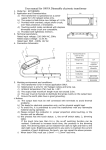
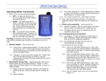
YSC-8330
USER MANUAL
XI’AN TYPICAL INDUSTRIES CO.,LTD.
Contents
1
2
3
4
5
6
7
8
Notice
1.1 Work environment
1.2 Notice of installation
1.3 Notice of safety
Installation and Adjustment
2.1 Controll box
2.2 Speed controller
2.3 Speed controller bracket (direct-driven)
2.4 Identifier
2.5 Servo motor (direct-driven)
2.6 Servo motor (belt-driven)
2.7 Magnetic synchronizer
2.8 Installation diagram of system
Power Connection
3.1 Single phase 220V power connection
3.2 Three phase 380V power connection
Connector Diagram
Function of Frant Panel
Function of Operation Box
Operation of the Normal Function Interface
7.1 Parameter setup
7.2 Parameter solidifying
7.3 Resumine parameter through One-Key Default
7.4 Access the special function parameter interface
7.5 Function of identifier
7.6 Adjust the tacking
7.7 Slow start function
7.8 Resume the default value of all parameters
7.9 Encrypt the parameter interface
7.10 Function of Machine LED
Operation of the Special Function Interface
8.1 Dynamic speed limitation
8.2 Counting the product quantity
8.3 Stitch length
1
Page
3
3
3
3
4
4
4
4
4
4
5
5
5
6
6
6
7
8
8
10
10
11
11
11
11
12
12
13
13
13
13
13
13
13
8.4 Different ratio
8.5 Actual speed display
8.6 Stitches statistic
8.7 Current time of power-on
8.8 Total time of power-on
8.9 Total idle time
8.10 Total working time
8.11 Using efficiency
9 General Parameter Table (part)
9.1
Speed parameter
9.2
Time parameter
9.3
Enable parameter
9.4
Degree parameter
9.5
Special function parameter
10 Measurement of Error and Warning
11 Signal Checking
12 Review the History Errors
14
14
14
14
14
14
14
14
15
15
15
16
18
19
20
20
23
Appendix I: 7-segment Display Characters Compare Table
Appendix II: How to adjust the speed controller
Appendix III: How to update the control box with the update module
24
25
26
2
1. Notice
YSC-8330 is used in system of industry sewing machine. For perfect
operation and safety, installation and operation must be supervised by
professional.
1.1
Work environment
▲ Please use 220V AC in ±10% ranges.
▲ To avoid the false operate, please keep the product away from the
high electromagnetic interference.
▲ Please operate in the area which temperature is 5℃~45℃.
▲ Please operate in the area which humidity is 80% or less.
▲ Please keep the product away from the flammability and exploder.
1.2
Notice of installation
▲ The control box should be installed correctly follow the instruction in
this manual.
▲ Turn off the power and unplug the cord before installation.
▲ The wire must not set to be near the wheel and other movable parts.
▲ To avoid the static interference and current leakage, all grounding
must be done.
1.3
Notice of safety
▲ Turn off the power before maintenance and repairs or raising the
machine arms, or changing needle, or threading needle.
▲ Please don’t open the box except the professional.
▲ When turn on the machine in the first time, use low speed to operate
and check the correct rotation direction.
▲ During machine operation, don’t touch any moving parts.
▲ All moving parts must use the protective device to avoid the body
contact and objects insertion.
▲ When there is water or other liquid, or caustic material on box or
motor, you must stop operation and turn off the power.
▲ All connector shouldn’t be plug and unplug when power on.
▲ The connector should be plug and unplug in the correct method.
3
2. Installation and Adjustment
2.1 Control box
Install the hook
Install control
on bedplate with
box.
4 M5 bolts.
2.2 Speed controller
2.3 Dimension of speed controller
bracket (direct-driven)
2.5 Dimension of servo motor (direct-driven)
4
2.4 Identifier
2.6 Dimension of servo motor (belt-driven)
2.7 Magnetic synchronizer
When install the
wheel, the first
hole must be
vertical to the
plane of the
main axis.
2.8 Installation diagram of system
5
3. Power Connection
3.1 Single phase 220V power connection
Ground wire (green & yellow) must be grounding.
3.2 Three phase 380V power connection
6
4. Connector Diagram
Attention:
for direct-driven is safety SW., and for belt-driven is
Synchronizer.
7
5. Function of Front Panel
State LED
z 1s alternation of twinkling indicate
idle status;
z Quickly twinkling indicate running
status;
z One time slowly twinkling and N
times quickly twinkling indicate
the error status, N is error code,
see P22.
AC220V power switch
→ Power off
→ Power on
6. Function of Operation Box
P106 operation box diagram (P104 can also be used for YSC-8330)
8
Function
Start Tacking
Selection
End Tacking
Selection
Free Sewing
Bar Tacking
Sewing
Single
Constant-Stitch
Sewing
Multi
Constant-Stitch
Sewing
Operation
Key
Double start tacking, A is the stitches of forth
sewing; B is the stitches of back sewing. They
are both in range 1~15.
Single start tacking, A is the stitches of forth
sewing; B is the stitches of back sewing. They
are both in range 1~15.
Double end tacking, C is the stitches of back
sewing; D is the stitches of forth sewing. They
are both in range 1~15.
Single end tacking, C is the stitches of back
sewing; D is the stitches of forth sewing. They
are both in range 1~15.
▲ As the pedal is stepped forward, the start
tacking(if selected) will be done automatically,
then machine will start normal sewing. Once the
pedal returned to balance, machine will stop
immediately.
▲ As the pedal stepped backward, the end
tacking, trimming and wiping(if selected) will be
done automatically.
▲ Once the pedal is stepped forward, all the
seams of bar tacking, A, B, C, D sections will
be completed with E times, and the trimming
will be done automatically.
▲ The pedal must be returned to balance for
next sewing.
▲ Once the pedal is stepped forward, F, G
stitches will be completed.
▲ Three mode (A, B or C) could be selected.
▲ Once the pedal is stepped forward, F, G
stitches will be completed with E times.
▲ Constant-Stitch Sewing will perform the
9
number of segments and times as setting, when
the stitches are zero, machine will stop
immediately.
Slow Start
Needle Up /
Needle Down
Trimming
Enable
Parameter
Function
Setup
Function
Interface
Selection
One-Key
Default
/
Lighting LED
Slow start switch, see 7.7.
Select the stop position of needle.
Enable or disable the trimming.
Enter or exit parameter function interface.
Confirm and save current value of parameter.
Switch current interface to another.
See 7.3 and 7.10.
Increase
Value increase.
Decrease
Value decrease.
7. Operation of the Normal Function Interface
The following opration could be valiable if normal function interface LED
.
is on, other interface could be entered though
7.1 Parameter setup
Press
will be into parameter interface, using E+ and E- to select
parameter type, using F+, F-, G+ and G- to select parameter index, value of
current parameter will be displayed on bar A~D, using increase and decrease
key can modify the value, as follow:
10
For example, the value of S01 is 4000. The bar will be twinkling if
modified, use
to confirm or
repeal change. After modifying, use
to back to sewing interface.
7.2 Parameter solidifying
If users want to change some parameter’s default value, then select the
parameter, press
maintain a moment, after “SD OK” displaying, the
default value has been changed.
7.3 Resumine parameter through One-Key Default
Select any parameter in parameter interface,
can be used to recall
the default value. The bar will be twinkling if modified, use
to confirm or
repeal change.
7.4 Access the special function parameter interface
Without any operation during power up, only S, T and A type parameter
can be select. Press
during power up will display “O EN”, and then O
type parameter can be accessed.
7.5 Function of identifier
The machine type code (O03) is associated with identifier automatically,
the parameter relative would refresh according to machine type. If any wrong
be with the identifier, it can be disabled and set by manual, as below:
▲ Press B+ during power up, “ID D” would be displayed then the
identifier is disabled;
▲ Set O03 to according with machine type;
▲ Set O30 to be ”ON” will re-enable the identifier function.
The default value of some parameters are different from machine type,
as below:
11
Default
S01
S03
S04
S05
S06
T01
T02
A05
O20
01
4000
2000
2000
2000
3000
42
45
OFF
ON
02
3000
1800
1800
1800
2000
53
48
OFF
ON
05
3500
1800
1800
1800
3000
42
45
OFF
ON
06
2500
1500
1500
1500
2000
59
57
OFF
ON
07
4000
2000
2000
2000
3000
41
36
ON
OFF
08
3000
1800
1800
1800
2000
59
45
ON
OFF
Code
10A
4000
2000
2000
2000
3000
41
36
OFF
OFF
11A
3000
1800
1800
1800
2000
59
45
OFF
OFF
12
3500
1800
1800
1800
2000
45
31
OFF
OFF
14
3500
1800
1800
1800
2000
57
46
OFF
OFF
7.6 Adjust the tacking
7.6.1 Adjusting of RVE. SOL. action time
For start/end tacking or bar tacking, if unbalanced situation is appeared
during natural direction to reverse direction, please correct it as below:
Decrease
Increase
parameter T01
parameter T01
7.6.2 Adjusting of RVE. SOL. release time
For start/end tacking or bar tacking, if unbalanced situation is appeared
during reverse direction to natural direction, please correct it as below:
Decrease
Increase
parameter T02
parameter T02
7.7 Slow start function
If
be effective, every new operation after trimming will run by slow
speed for several stitches firstly, speed is relative with parameter S08, stitch is
relative with parameter O01.
12
7.8 Resume the default value of all parameters
Set parameter O17 to “ON”, turn on the power again, after twinkling of
“INIT” finished, all parameters have been default value themselves.
7.9 Encrypt the parameter interface
First change parameter O27 for user’s password, then set parameter
O15 “ON” to enable password, after this, accessing to parameter interface will
be in password interface firstly, set the correct password and use
to
confirm.
7.10 Function of Machine LED
The lighteness of LED can be set by
in sewing interface, the
lighteness increase 20% each press, if 100% already, turn to 0%, and so on.
8. Operation of the Special Function Interface
Press
could be access special function interface from normal
function interface, showed as below:
Bar A and B according to SN of function, bar D~G display parameter,
press B+ and B- to select function:
8.1 Dynamic speed limitation
SN F1, display current speed up limitation, could be change during
running.
8.2 Counting the product quantity
SN F2, display the product quantity, increase for 1 after trimming.
8.3 Stitch length
SN F3, according to actual stitch length.
13
8.4 Different ratio
SN F4, while using puller, display the different ratio for stitch length.
8.5 Actual speed display
SN F5, display the actual speed.
8.6 Stitches statistic
SN F6, display the stitches statistic of each working procedure.
8.7 Current time of power-on
SN F7, for example, current time of power-on is 6 hours and 13 minutes.
8.8 Total time of power-on
SN F8, for example, total time of power-on is 130.8 day.
8.9 Total idle time
SN F9, for example, total idle time of power-on is 12.5 day.
8.10 Total working time
SN FA, for example, total working time of power-on is 118.3 day.
8.11 Using efficiency
14
SN FB, for example, current using efficiency is 90.4%.
9. General Parameter Table (part)
9.1 Speed parameter
SN
Name
S01
Max speed
S02
Min speed
S03
S04
S05
S06
S07
S08
Range
500~5000
(s/m)
150~500
(s/m)
Speed of start
500~2500
tacking
(s/m)
Speed of end
500~2500
tacking
(s/m)
Speed of bar
500~2500
tacking sewing
(s/m)
Speed of C-S
500~4500
sewing
(s/m)
Trimming
150~300
speed
(s/m)
Slow sewing
200~500
speed
(s/m)
Default
Description
See 7.5
Maximum speed.
150
Minimum speed.
See 7.5
Speed of start tacking.
See 7.5
Speed of end tacking.
See 7.5
Speed of bar tacking sewing.
See 7.5
Speed of constant-stitch sewing.
200
Speed of trimming.
400
Slow sewing speed when start.
9.2 Time parameter
SN
Name
T01
RVS action time
T02
RVS release time
T03
T04
Range
1~200
(ms)
1~200
(ms)
Delay time of
1~200
wiper
(ms)
Action time of
1~200
wiper
(ms)
Default
Description
See 7.5
Action time of the REV SOL.
See 7.5
Release time of the REV SOL.
20
Timing before the wiper solenoid act.
30
Timing for the wiper solenoid action.
15
T05
T06
T07
T08
T10
Delay time of foot
1~500
lifter
(ms)
Release time of
1~500
foot lifter
(ms)
Time of foot lifter
1~999
whole output
(ms)
Time of RVS
1~999
whole output
(ms)
Time of remove
1~500
shake
(ms)
10
50
500
150
10
Timing before the foot lifter solenoid is
act.
Timing before the foot lifter solenoid is
released.
Timing of the foot lifter solenoid is act
with whole output.
Timing of the reverse solenoid is act
with whole output.
The speed controller will be greater
sensitive when the value is smaller.
9.3 Enable parameter
SN
Name
Range
Default
A01
Up position
ON~OFF
ON
A02
A03
Automatically
sewing
mode of stitch
correction
Description
ON: the stop position is up
OFF: the stop position is down
Valid only in constant-stitch sewing,
ON~OFF
ON
when set to “ON”, enable the automatic
sewing.
ON~OFF
OFF
ON: continual
OFF: half needle
For free sewing, if there is single switch
on machine arms, when set to “OFF” the
Stitch
A04
correction with
ON~OFF
OFF
single button
switch is reverse switch always. When
set to “ON”, the switch is reverse switch
at sewing and is stitch correction switch
at stop.
When set to “ON”, enable the reverse
and stitch correction switch both are
Stitch
A05
correction with
ON~OFF
See 7.5
double button
valid. When set to “OFF”, disable the
double key be valid at the same time,
and in this mode, the function of the
single switch is determined by A04.
A06
A07
Trimming
ON~OFF
ON
When it is “ON”, enable the trimming.
Wiping
ON~OFF
ON
When it is “ON”, enable the wiping.
16
When A06 is “OFF”, A07 is invalid.
When it is “ON”, enable foot lift. Whether
A08
Foot lift
ON~OFF
ON
the foot SOL to be connected is detected
during power on automatically.
A09
clamp
ON~OFF
OFF
“ON” to enable clamp, only for GC6280.
When it is “ON”, the pedal must be back
A14
Trimming
protection
ON~OFF
to the balance position to do next
ON
operation after trimming, “OFF” to be no
required.
A15
Foot lift after
trimming
When A08 is “ON”, if A15 is set to “ON”,
ON~OFF
OFF
the foot lifter will lift automatically after
trimming.
It is valid only for constant-stitch sewing.
If enable automatic sewing mode and set
The first
the start tacking, the next segment of
segment keep
A16
on with the
constant-stitch
ON~OFF
ON
sewing
will
do
automatically after the start tacking is
start tacking of
finished when it is “ON”. When it is “OFF”
C-S sewing
or disable the automatic sewing mode,
machine will stop automatically after the
start tacking is finished.
It is valid only for constant-stitch sewing.
If enable automatic sewing mode, the
end
A17
tacking
and
trimming
will
do
The end
automatically after the last segment of
tacking keep
constant-stitch sewing is finished when it
on with the last
ON~OFF
ON
is “ON”. When it is “OFF” or disable the
segment of
automatic sewing mode, machine will
C-S sewing
stop automatically after the last segment
of constant-stitch sewing is finished. The
end tacking and trimming will do until
step forward the pedal again.
A18
Move to up
position after
ON~OFF
OFF
17
When it is “ON”, the machine will move to
up position and stop automatically as
A19
power on
power on.
Foot lifer
When the pedal is half back toe down, if
acting in foot
ON~OFF
ON
it is “ON”, the position is foot lift. If it is
lift position
“OFF”, the position is to be balance.
Trimmer acting
A20
in foot lift
ON~OFF
OFF
ON~OFF
OFF
When it is “ON”, the trimming will at the
foot lifter position.
position
A21
Soft start
When it is “ON”, it will do a soft start after
trimming.
9.4 Degree parameter (can be accessed by press
SN
Name
Range
Default
D01
Up lever
D02
Down lever
D03
Trimmer act
D04
D05
D06
0~359
(°)
0~359
(°)
0~359
(°)
Trimmer
0~359
release
(°)
Reverse act
0~359
(°)
Reverse
0~359
release
(°)
D07
Clamp act
D08
Clamp release
D09
Puller start
D10
Puller end
0~359
(°)
0~359
(°)
0~359
(°)
0~359
(°)
during power on)
Descriptions
60
Up lever degree.
215
Needle bar down degree.
250
Trimmer act degree.
0
Trimmer release degree.
300
Reverse SOL. act degree.
300
Reverse SOL. act release degree.
180
Clamp act degree.
270
Clamp release degree.
50
Puller starts degree per round.
120
Puller stops degree per round.
18
9.5 Special function parameter (can be accessed by press
during power
on)
SN
Name
Range Default
Descriptions
O01
O03
Stitches of slow
0~10
sewing at start
(needle)
Machine type
1~30
Duty of foot lifter
10~99
output
(%)
The stitches of slow sewing at start
3
when trimming is finished. The
speed of slow sewing is set in S08.
See 7.5
According to the machine type.
The duty cycle of PWM for signal of
O05
50
foot lifter solenoid. The power will be
greater if this value is bigger, at the
same time, the heat is more.
O06
Foot lifter release
timed
When it is “ON”, the foot lifter
ON~OFF
ON
solenoid
will
be
released
automatically after the time desired.
When it is “ON”, the RVS solenoid
O06
RVS release timed
ON~OFF
ON
will be released automatically after
the time desired.
O15
O17
O23
O24
Parameter encrypt
Initialization of
parameters
Running time of
aging test
Idle time of aging
test
ON~OFF
OFF
See 7.9.
ON~OFF
OFF
See 7.8.
1~60(s)
5
The running time of aging test.
1~60(s)
5
The idle time of aging test.
Total time of aging
1~255
test
(h)
O26
O27
O30
Aging test enable
ON~OFF
OFF
“ON” to active the aging test.
User’s password
0~9999
1234
See 7.9
Identifier enable
ON~OFF
ON
See 7.5.
O31
Safety SW. enable
ON~OFF
See 7.5
O32
Safety SW. mode
0~1
1
O25
1
19
The total time of aging test. It will be
stopped when reached the time.
“ON” to enable the safety switch
function.
0: Normal close, 1: Normal open.
10. Measurement of Error and Warning
Error
code
E01
E02
E05
E08
E09
E10
E13
E14
E15
E16
E17
Causation
Voltage is too high
Voltage is too low
Break ineffective
Load is too heavy
Speed controller error
Position check error
Machine type error
Trimmer SOL. error
REV SOL. error
Wiper SOL. error
Foot lifter SOL. error
Pedal warning
Safety SW warning
Inspector disconnected
warning
Measurement
Check the AC power.
Check the AC power.
Replace break resistor.
Check the load.
Check speed controller, see 11.1.
Check synchronizer, see page 11.2.
Check identifier, see 7.5.
Check SOL. whether direct short.
Check SOL. whether direct short.
Check SOL. whether direct short.
Check SOL. whether direct short.
Release the pedal to balance position.
Check Safety SW., or set O32 to match
the machine type.
All automatic functions will be no
effective.
11. Signal Checking
Press
during power on, it will display “TEST” and then enter the
mode of Measurement of Input Signal. Bar A show the SN.
11.1 Speed controller
Display of the different pedal position as below:
Display code
Meanings
Descriptions
FS02~FS99
High speed The second segment forward, pull is 02~99.
LS01
Low speed The first segment forward, pull is 01.
BL-Balance
Default.
FP-Foot lifter
The first segment backward.
TM-Trimming
The second segment of backward.
20
ERRO
Fault
Speed controller fault or disconnected.
11.2 Synchronizer
Bar D and E denote the up position, bar C and D denote the down
position. Turn the hand wheel by hand equably, display of different position as
below:
Display code
Meanings
Descriptions
UP-Needle up position
In up position.
--DW
Needle down position In down position.
---Other position
Neither in up or down position.
ERRO
Fault
Both in up and down position.
11.3 Switch
E – REV. SW.
F – COR. SW.
G -- Safety SW.
11.4 Hall signal of motor
Turn the hand wheel by hand equably, display the hall signal of motor,
range is 0~7. If the fault state appeared, then display “ERRO”.
11.5 Encoder signal of motor
Turn the hand wheel by hand equably, display the encode count of motor,
the error is ±5 normally.
11.6 Solenoid
Through D+, D-, E+ and E- to select the SOL, use G+ to test, as below:
21
Display code
TM
WP
SOL
Trimmer SOL
Wiper SOL
Display code
RV
FP
SOL
REV SOL
Foot Lifter SOL
11.7 Identifier
Display the code of identifier, see page 16. Display “ERRO” while fault.
11.8 Version of software
For example, the version is v 1.00.
11.9 AC power
Display the current AC power is 220V.
11.10
SOL. DC power
Display the current SOL. DC power is 31.2V.
11.11
Machine degree
First to setup zero point, use C+ or C- to change degree type, turn hand
wheel equably, display the current degree.
¾ Zero point (display “ZO”)
to set zero
Turn hand wheel to top dead center, and then press
degree point.
¾ Up lever (display “UP”)
Turn hand wheel to up lever, press
to save current degree to up
lever position. If display is equal to existent parameter, a twinkling “O” will be
22
displayed in bar D.
The setup of other degree parameters are same with above.
¾ Down lever (display “DW”)
¾ Trimmer act (display “TA”)
¾ Trimmer release (display “TR”)
¾ Reverse act (display “RA”)
¾ Reverse release (display “RR”)
¾ Clamp act (display “CA”)
¾ Clamp release (display “CR”)
¾ Puller start (display “PS”)
¾ Puller stop (display “PE”)
12. Review the History Errors
The system can save the error code automatically when error occurred.
Checking the history error by operation as below:
▲ Press D+ during power on to access the history errors interface;
▲ Press A+ and A- to check the 10 error code of recent, Display “NO” if
there is no error;
▲ Bar C refer to the error index, bar D~G display the message, as
below:
Index
Message
A
Error code
B
AC power of the time
C
DC power of the time
F
Speed of the time
G
Year of the time, such as 2008
H
Date of the time, for example, 0804 indicate Aug. 4
I
Time of the time, for example, 1510 indicate 15:10
23
Appendix I: 7-segment Display Characters Compare Table
Arabic Number
0
Actual
1
2
3
4
5
6
7
8
9
Display
English Alphabet
Actual
A
B
C
D
E
F
G
H
I
J
K
L
M
N
O
P
Q
R
S
T
U
V
W
X
Y
Z
Display
Actual
Display
Actual
Display
24
Appendix II: How to adjust the speed controller
If the magnet in speed controller has been replaced, or installation
position of PCB has been changed, new adjustment should be performed.
Each position showed as below:
Balance position
Foot lifter position
Farthest position backward
Farthest position forward
Steps of adjustment showed as below:
z Push the switch on PCB of speed controller during the power on;
z Release the switch, after setting the speed controller to balance
position, press the switch once;
z After setting the speed controller to the farthest position forward,
press the switch once again;
z After setting the speed controller to the foot lifter position, press the
switch once again;
z After setting the speed controller to the farthest position backward,
press the switch once again;
z After all, the adjustment is accomplished, all function would be normal
after power on again.
25
Appendix III: How to update the control box with the update module
User could update software of control box by update module if necessary,
the operations showed as below:
z Turn off the power, plug the update module into identifier socket ,
then power on again;
z The error code “E 23” would be displayed if not matching;
z “UM xxx” would be displayed if matching, and xxx denote version of
update module;
z Press S to start update procedure, it will be accomplished after “UM
ok” displayed. All procedure will take in half minute. Then Turn off the
power and plug the identifier, all function would be normal after power
on again.
26
Add:No.1 Taibai South Road,
Xi’an, P.R.China-710068
Tel:+86-29-88279162 88279163
Fax:029-88279161 83911111
E-mail: [email protected]
Http://www.chinatypical.com
V3