1
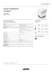
T L Audio
IVORY SERIES
User Manual
EQ-5013
VALVE EQUALISER
Tony Larking Professional Sales Limited,
Letchworth, England.
interstage
Phistersvej 31, 2900 Hellerup, Danmark
Telefon 3946 0000, fax 3946 0040
www.interstage.dk
- pro audio with a smile
INTRODUCTION
The T L Audio Ivory Series consists of a range of hybrid valve signal processors, which utilise low noise
solid state electronics in conjunction with classic valve circuitry to produce audio processing units offering
very high quality signal paths with the unique valve audio character. The Ivory Series units offer
comprehensive control facilities, whilst remaining straight-forward to operate, and represent excellent value
for money.
The 5013 Parametric Equaliser offers four bands of fully variable equalisation on each of its two channels.
Both channels feature balanced and unbalanced line level inputs, plus a front panel auxiliary instrument input.
The block diagram of one of the channels is shown in fig.1. The balanced line input is connected via an XLR
socket, whilst the unbalanced connection is via a 0.25” TRS jack socket. The nominal input levels are
+4dBu and -10dBu on the balanced and unbalanced inputs respectively, but these may be shifted to
+18dBu and +4dBu respectively by the input level switch. This feature offers greater flexibility of
connection to other equipment, particularly the latest generation of digital recorders which require a
comparatively high input level. The line inputs have an overall gain range of -20 to +20dBu.
The front panel mounted auxiliary instrument jack socket allows direct access to the channel inputs. The
input is suitable for a variety of sources, including guitar, acoustic pickup and keyboard. The instrument
input is also controlled by the input gain potentiometer, and will accept a wide range of sources from
passive pickups to active guitars and keyboards. The input stage is monitored by the “Drive” and “Peak”
LEDs. Drive is a variable intensity LED designed to indicate the signal level through the valve stages, and
thus the amount of “warming” applied to the signal. Peak is a conventional warning that clipping is about to
occur, and will illuminate if there is an excessively high level present at any point in the signal chain.
Both channels feature a four band parametric equaliser. All of the EQ bands comprise centre-detented cut
and boost control, swept frequency and continuously variable Q controls.
Master level controls are provided, post EQ. These controls are also centre-detented for ease of line-up,
but may be varied in conjunction with the input gain controls to alter the operating level through the circuitry,
optimising the operating level and hence headroom and signal to noise ratio of the unit.
The output is via a balanced XLR socket at a nominal level of +4dBu, with an unbalanced output on a jack
socket at a nominal level of -10dBu. Complementary to the input level switch, an output nominal level
switch is located adjacent to the sockets, to match the balanced and unbalanced outputs to a wide variety
of equipment.
Please read this manual fully before installing or operating the Equaliser.
PRECAUTIONS
The T L Audio EQ-5013 Equaliser requires very little installation, but like all electrical equipment, care must
be taken to ensure reliable, safe operation. The following points should always be observed:
- All mains wiring should be installed and checked by a qualified
electrician,
- Ensure the correct operating voltage is selected on the rear panel
before connecting to the mains supply,
- Never operate the unit with any cover removed,
- Do not expose to rain or moisture, as this may present an electric
shock hazard,
- Replace the fuse with the correct type and rating only.
Warning: This equipment must be earthed.
INSTALLATION
AC Mains Supply.
The unit is fitted with an internationally approved 3 pin IEC connector. A mating socket with power cord is
provided with the unit, wired as follows:
Brown: Live.
Blue:
Neutral.
Green/Yellow: Earth (Ground).
All mains wiring should be performed by a qualified electrician with all power switched off, and the earth
connection must be used.
Before connecting the unit to the supply, check that the voltage selector switch on the rear panel is correctly
set. The unit may be set for 115V (accepting voltages in the range 110V to 120V, 60Hz AC), or to 230V
(for voltages in the range 220V to 240V, 50Hz AC). Adjustment to the operating voltage should be made
by sliding the selector switch left or right with a small screwdriver until the desired voltage is displayed. The
mains fuse required is 20mm anti-surge, 1AT rated at 250V. If it ever necessary to replace the fuse, only
the same type and rating must be used. The power consumption of the equipment is 30VA.
Warning:
attempted operation on the wrong voltage setting, or with an
fuse, will invalidate the warranty.
incorrect
Audio Operating Level.
The equaliser is equipped with inputs and outputs suitable for connection to a wide variety of other audio
equipment. Generally, the balanced XLR connections will be required for interfacing to other professional
equipment, where the operating level (line-up level or nominal level) will be +4dBu, or approximately 1.2V
rms. The unbalanced jack connectors are generally intended for interfacing to semi-professional equipment
and have an operating level of -10dBu, or about 225mV rms. However, the input and output level switches
allows these levels to be shifted by 14dB, i.e. to +18dBu on the XLRs (suitable for high levels from a digital
tape), and +4dBu on the unbalanced jacks.
The equaliser may be used to change between operating levels, for example by connecting the unbalanced
output of a semi-pro mixing console to the equaliser’s unbalanced input, and taking the balanced output of
the equaliser to the balanced input of a tape machine at +4dBu. All line level inputs and outputs of the
equaliser may be used simultaneously if required. Balanced interconnection is always preferable to obtain
the best headroom and noise rejection, but can only be used if the other equipment in the chain, e.g. the
mixing console, also has provision for balanced connections.
Audio Inputs.
Line Input.
The line level input is via a 3 pin female XLR connector, suitable for balanced or unbalanced line sources at
a nominal level of +4dBu. The mating connector should be appropriately wired as follows for balanced or
unbalanced operation:
Balanced inputs:
- Pin 1 = Ground (screen).
- Pin 2 = Signal Phase (also known as “+” or “hot”).
- Pin 3 = Signal Non-Phase (“-” or “cold”).
Unbalanced inputs:
- Pin 1 = Ground (screen)
- Pin 2 = Signal Phase (“+” or “hot”).
- Pin 3 = Signal Ground
When using unbalanced signals, the signal ground may be obtained by linking pins 1 and 3 in the mating
XLR connector. If this connection is not made, a loss in level may result.
Unbalanced Line Inputs.
An unbalanced line level input at a nominal level of -10dBu is also provided, on a 0.25” mono jack socket.
The mating plugs should be wired as follows:
- Tip
= Signal Phase (“+” or “hot”).
- Screen = Ground.
Auxiliary Instrument Inputs.
A 2 pin (mono) jack plug is required, which should be wired as follows:
- Tip
= Signal Phase (“+” or “hot”).
- Screen = Ground.
The auxiliary input is suitable for direct connection of instruments including guitars and keyboards. Good
quality screened cable should be used, particularly for microphone or low level sources, to prevent hum or
noise pickup.
Balanced Output.
The output is via a balanced, 3 pin male XLR connector. The mating connector should be wired as follows:
- Pin 1 = Ground (screen),
- Pin 2 = Signal Phase (“+” or “hot”),
- Pin 3 = Signal Non-Phase (“-” or “cold”).
Unbalanced Output.
An unbalanced line output is provided for each channel, on a 0.25” mono jack socket.
- Tip =
Signal Phase (“+” or “hot”).
- Screen = Ground.
Mounting.
The equaliser may be free standing, or mounted in a standard 19” rack. Always ensure that the cooling
vents on the front and sides are clear of obstruction, and do not subject the unit to an external source of
heat (by mounting immediately above a power amplifier, for example). If used free standing, ensure that the
equipment is protected against rain and spillage of liquid.
Rear Panel.
The rear panel connectors are identified in fig.3. Make sure that all settings, mains and audio connections
have been made as described above before attempting to operate the equipment.
OPERATION.
Front Panel.
The front panel controls are identified in fig.2.
Line Input.
A line level signal should already be at about the correct operating level, but check that the input level
switch is correctly set. An input gain adjustment may be made if necessary.
Aux Instrument Input.
The front panel auxiliary instrument input socket is suitable for low level sources such as microphones, pick
ups or passive guitars and higher level sources such as active guitars and keyboards. The instrument input is
also controlled by the input gain control. Due to the wide range of the input, a high level of gain is available
in the equaliser, and care should be taken not to apply excessive input gain to a high level signal.
DRIVE and PEAK LEDs.
The orange Drive LED provides a visual indication of the signal level through the valve stages, and therefore
the extent of “warming” or valve character being introduced. The drive LED will gradually illuminate as the
input level or gain is increased, over the range 0dB to +12dB.
The red Peak LED operates as a conventional warning that clipping is about to occur. The operating level
of the entire signal chain is monitored, and the LED illuminates when there is less than 5dB of headroom
remaining.
If the input and output gain controls are set to their centre, 0dB, positions and there is no EQ boost applied,
the Peak LED will illuminate some 8dB after the Drive LED has reached its full intensity. However, it is
possible to add gain further down the chain (EQ boost or output level gain), which will cause the Peak LED
to illuminate at a lower level of Drive. This situation implies that a high level of “clean” signal is present,
without driving the valves at a high level.
Equalisation.
Before switching the EQ into circuit, it is advisable to set the cut/boost controls to their centre, or flat,
position. The EQ is brought into circuit with the overall “EQ-IN” push switch, signalled by a green LED.
Both channels feature four bands of equalisation, all with fully variable cut and boost controls offering +/15dB of range, swept frequency and variable Q. (The “Q” of the filter is a measure of the shape of the
frequency response curve, and is closely related to the bandwidth, or range of frequencies controlled by the
filter). High Q settings (about 5 at the maximum setting on the 5013) result in sharp, narrow bandwidths
generally used for audio correction or effects. Intermediate settings, say 1 to 3, are generally used to
enhance or reduce a broader range of frequencies, typically to make an instrument or vocal “stand out”, or
recede, into the mix. Finally, low Q values (down to about 0.5 on the 5013) provide more gentle
contouring, or “sweetening” of the response.
The four bands of EQ per channel are nominally designated as LF (low frequency), LM and HM (low and
high mid frequency) and HF (high frequency). However, the frequency variation available on each band
allows overlapping of two, or more, bands into the same frequency range. This arrangement affords
maximum flexibility, allowing for example, reduction of a narrow band whilst simultaneously boosting an
overlapping broader band of frequencies. Used individually or in combination the filter bands allow
comprehensive equalisation of any audio signal.
Typical response curves and the effect of control setting variations are shown in the specification section of
this manual. Note the wide, 10Hz to 40KHz bandwidth of the 5013.
Output Level.
The output level control is centre-detented for 0dB gain, with +/-20dB of gain available. The additional gain
may be useful if the output of the equaliser is connected directly to a digital recorder which requires a high
level of modulation. Note that applying additional gain at the output will not increase the dynamic range of
the signal, but will increase the noise level as well as the audio signal being recorded, and should therefore
only be used if an output level in excess of the nominal +4dBu is required.
SPECIFICATIONS
Balanced Line Input:
Electronically balanced, unbalanced compatible, with input
impedance greater than 5Kohm.
Gain range -20dB to +20dB.
Nominal input level +4dBu.
Maximum input level +26dBu.
3 pin female XLR connector.
Unbalanced Input:
Input impedance greater than 5Kohm.
Gain range -20dB to +20dB.
Nominal input levels -10dBu.
Maximum input level +12dBu.
2 pole 0.25” jack socket.
Input Level Switch:
Converts the balanced and unbalanced line level inputs to
+18dBu and +4dBu nominal respectively.
Instrument Input:
Gain control range 40dB.
Maximum input level +12dBu.
2 pole 0.25” jack socket.
Equalisation:
Four bands per channel, with overall EQ ON switch.
Each band fully parametric, peaking response, with continuously
variable cut/boost, frequency and Q.
Cut and boost: +/-15dB.
Q range 0.5 to 5.
Frequency range,
LF:
LM:
HM:
HF:
30Hz to 1KHz,
100Hz to 3KHz,
1KHz to 12KHz,
3KHz to 20KHz.
Output Gain Control:
0dB at centre, +/-20dB gain variation.
Balanced Outputs:
Output impedance 47 ohms.
Maximum level +26dBu.
3 pin male XLR connector.
Unbalanced Outputs:
Output impedance 47 ohms.
Maximum level +18dBu into 10Kohms.
2 pole 0.25” jack socket.
Output Level Switch:
Converts the balanced and unbalanced line level outputs to
+18dBu and +4dBu nominal respectively.
Frequency Response:
10Hz to 40KHz, +0, -1dB.
Noise:
-80dBu, 22Hz to 22KHz, line input selected at 0dBu input and
output gain, equaliser on and flat.
Dynamic Range:
106dB (Line input @ 0dB gain).
Dimensions:
Weight:
19” rack mounting, 2U high.
483mm wide x 88mm high x 200mm deep.
2.5Kg.
Power Requirements:
Rear panel selectable for 220-240V 50Hz or 110-120V 60Hz
operation.
Rear panel fuse 20mm, 1AT, 250V.
Power consumption 20VA typical.
Detachable 3 pin IEC connector, mating connector and cable
Front panel On/Off switch with green LED.
supplied.
The above specifications are subject to change without notice.
SERVICE
Should the equaliser require service, it must be taken or posted to an authorised dealer. Please retain the
original packing for possible future use, and ensure the unit is suitably protected during transit. The
manufacturer cannot accept responsibility for damage caused during transportation.
The equaliser is supported by a limited warranty for a period of one year from the date of purchase. During
this period, any faults due to defective materials or workmanship will be repaired free of charge. The
warranty excludes damage caused by deliberate or accidental misuse, operation on the incorrect mains
voltage, or without the correct type and value of fuse fitted. It is the user’s responsibility to ensure fitness for
purpose in any particular application. The warranty is limited to the original purchase price of the equipment,
and excludes any consequential damage or loss. Please include proof of purchase date if claiming repair
under warranty.
For your own records, please complete the following details:
Serial Number.............................
Date purchased...........................
Dealer.........................................