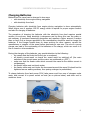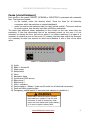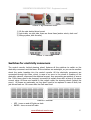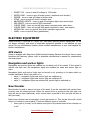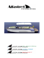
1
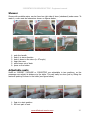
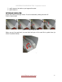
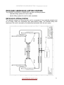
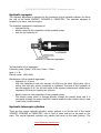
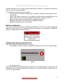
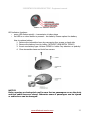
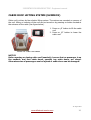
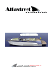
23SPORT&23CRUISE&23ELECTRIC– Equipment manual
www.alfastreet-marine.com
2
23SPORT&23CRUISE&23ELECTRIC– Equipment manual
Index of Content
WELCOME ON BOARD..............................................................................................................................4
ELECTRICAL SYSTEM...............................................................................................................................6
DIAGRAM OF THE VESSEL’S ELECTRIC CIRCUITS.................................................................................7
CHARGING BATTERIES........................................................................................................................8
FUSES (CIRCUIT BRAKERS).................................................................................................................9
SWITCHES FOR ELECTRICITY CONSUMERS........................................................................................10
ELECTRIC EQUIPMENT...........................................................................................................................11
GPS DEVICE......................................................................................................................................11
NAVIGATION AND ANCHOR LIGHTS...................................................................................................11
BOW THRUSTER...............................................................................................................................11
ANCHOR WINCH...............................................................................................................................12
STOVE PARAFIN OIL/GAS..................................................................................................................13
PRAFIN OIL STOVE.......................................................................................................................13
GAS STOVE..................................................................................................................................16
REFRIGERATOR.................................................................................................................................16
STEREO AM/FM, USB/MP3 PLAYER.....................................................................................................17
OTHER EQUIPMENT...............................................................................................................................18
CHEMICAL TOILET............................................................................................................................18
SHOWER..........................................................................................................................................20
ADJUSTABLE SEATS...........................................................................................................................20
STORAGE SHELVES...........................................................................................................................21
DECK AND CABIN ROOF LIFTING SYSTEMS........................................................................................22
CABIN ROOF LIFTING SYSTEM (SUNDECK)........................................................................................26
www.alfastreet-marine.com
3
23SPORT&23CRUISE&23ELECTRIC– Equipment manual
WELCOME ON BOARD
Congratulations for becoming the owner of the vessel 23SPORT, 23CRUISE or
23ELECTRIC. Alfastreet Marine greets you and welcomes you into the company of owners
and lovers of vessels. Take your time to carefully read these guides and their attachments.
This publication will help you to answer all the questions you might have regarding the
vessel. In case you have additional questions, please contact the salesperson. Alfastreet
wishes you to feel comfortable and safe on your vessel from the first experience onwards.
Please complete the chart below so that the important information about your vessel and
its manufacturer shall be gathered in one place and quickly available when you need
them.
Vessel model:________________________________________________
Vessel identification number:____________________________________
Vessel registration number:_____________________________________
Serial number of propulsion aggregate:___________________________
Manufacturer'sepresentative:___________________________________
Representative's address:______________________________________
Representative's telephone number :_____________________________
Authorised service centre :_____________________________________
Authorised service centre's address :_____________________________
Authorised service centre's telephone number:_____________________
NOTES:
_________________________________________________________________________
_________________________________________________________________________
_________________________________________________________________________
_________________________________________________________________________
_________________________________________________________________________
_________________________________________________________________________
_________________________________________________________________________
_________________________________________________________________________
_________________________________________________________________________
_________________________________________________________________________
_________________________________________________________________________
_________________________________________________________________________
_________________________________________________________________________
www.alfastreet-marine.com
4
23SPORT&23CRUISE&23ELECTRIC– Equipment manual
Our contact information:
Alfastreet d.o.o. - Alfastreet MARINE
Partizanska 129, SI-6210 SEŽANA, SLOVENIA
tel. n.: +386 5 70 72 100
fax:
+386 5 70 72 127
website:
www.alfastreet-marine.com
Contact person:
Tjaša Luin Peric
Chief executive officer
email: [email protected]
tel. n.: +386 5 70 72 101,
mobile: +386 41 388 166
Technical support:
Dejan Ravbar
email: [email protected]
tel. n.: +386 5 70 72 140
QR codes:
WEB page
www.alfastreet-marine.com
www.alfastreet-marine.com
5
23SPORT&23CRUISE&23ELECTRIC– Equipment manual
ELECTRICAL SYSTEM
The electricity consumers of the vessel works on a DC 12V voltage. The sources of the
supply voltage are two 12V/95Ah lead-acid batteries installed in the hull (in the stern),
near the engine. One supplies all electric consumers, the other suppleis the engine. If the
vessel is equipped with electric engine, number of batteries and type of it, depends on
customer's choice or engine manufacturer. Batteries for supplying the engine are then
installed under the table, near water tank. As with any other circuit, you must be careful
not to cause any short circuits between the drivers on the vessel. You must also be careful
during any interventions in the battery area. If a conductive object falls on the battery
clamps and causes a short circuit between the poles of the battery, this causes a large
current, sparkling and could result in a fire on board the vessel. All electric circuits are
secured with automatic fuses.
There are two major electric circuits:
• service electric circuit (used to supply all electrical consumers)
• engine electric circuit (used to start engine)
Both circuits has main switches to cut power from batteries to consumers. Switches are
located in cockpit under steering wheel, behind doors. When leaving the vessel is is
recommended to put switches to OFF position to prevent inconveniences.
There is also an emergency switch, which connects both batteries together in case if
engine can't be started with its battery. Emergency switch is located near both main
switches and is marked with “EMERGENCY” sign.
Emergency switch can be used only in emergency situations. In normal
operation it must be in OFF position!
www.alfastreet-marine.com
6
23SPORT&23CRUISE&23ELECTRIC– Equipment manual
Diagram of the vessel’s electric circuits
This chapter features a presentation of the electrical circuits on the vessel.
Picture 1: Diagram of the vessel’s electric circuits
www.alfastreet-marine.com
7
23SPORT&23CRUISE&23ELECTRIC– Equipment manual
Charging Batteries
Batteries on the vessel can be charged in two ways:
• with electricity from engine during navigation
• with electricity from land
Charging batteries with electricity from engine during navigation is done automaticaly.
When engine runs it produce 12V DC energy which is reqired for proper engine function
and also for charging of batteries.
The procedure of charging the batteries with the electricity from land requires special
caution. As we know, using electricity is dangerous and by doing this near the water or
wet surfaces, it becomes increasingly dangerous and requires a higher amount if caution
than on land. Only a charger approved by the manufacturer should be used to charge the
batteries. If the charger breaks down or stops working for other reasons, consult the
manufacturer or supplier of the vessel before purchasing a new one. The use of a wrong
charger can lead to the overloading of the batteries or the charger, which can result in a
fire on board or other accidents.
During the charging of the batteries, pay special attention to the following:
• the vessel must be firmly tied to the pier or anchored,
• all electric current-users on board the vessel must be switched off (the main
switches of the current-users and the motor are positioned on „OFF“ ),
• make sure that the feeder cable which connects the vessel to the electric current is
not damaged,
• the feeder cable must not touch water,
• the feeder cable must not hinder the movement around the vessel (it should not be
tightened across walking surfaces, thus posing a danger to pedestrians).
To charge batteries from land power 220V, take power cord from one of storages under
seats, and connect it to power socket on boat (as on picture below) and other end to
socket on shore.
Picture 2: 230V charging power cord
www.alfastreet-marine.com
8
23SPORT&23CRUISE&23ELECTRIC– Equipment manual
Fuses (circuit brakers)
Each circuit on the vessel 23SPORT, 23CRUISE or 23ELECTRIC is protected with automatic
fuse. The fuses are located:
• on the cockpit, under the steering wheel. There are fuses for all electricity
consumers which has switches on cockpit dashboard.
• under the seat on the starboard side (on right, behind cockpit). There are switches
for anchor winch, bow thruster and deck roof lifting mechanism.
The fuses have different values, depending on the current on the user which they are
protecting. If the fuse disconnects due to an increased current on the user, it is not
necessary to change the fuse, but only to switch it on. Before switching it on again it is
necessary to repair the error on the circuit. If, however, the fuse does need to be changed,
it is necessary to take into account its value and substitute it with a fuse of the same
value.
Figure 1: Fuses and main switches
Picture 3: Fuses and main switches
A)
B)
C)
D)
E)
F)
G)
H)
I)
J)
K)
L)
M)
Lights
Radio + Socket12V
Water pump
Refrigrerator
Stove
Navigation lights
Instruments (GPS device)
Bilge pump 1
Bilge pump 2
Horn + actuators
Service battery - Battery1 (main on/off switch for all electrical consumers)
Deck roof lifting system switch
Emergency, parallel switch (it connects both batteries in parallel for )
!
WARNING
EMERGENCY PARALLEL switch connects
both batteries in parallel. It can be used
exclusively in state of emergency, when
engine can't be started with engine battery,
or in case of engine's battery fauilt.
www.alfastreet-marine.com
9
23SPORT&23CRUISE&23ELECTRIC– Equipment manual
Picture 4: Big consumers fuses
1) lift the stair behind driver's seat
2) look inside, on right side, there are three fuses (anchor winch, deck roof
3) lifting system, bow thruster)
Picture 5: Fuse state
Switches for electricity consumers
The control console, behind steering wheel, features all the switches to switch on the
electricity consumers and the fuses. All the switches are watertight, so you can be carefree
about the water breaking into the control console. All the electricity consumers are
connected through the fuses, which, in case of an error in the circuit or flooding of the
electricity network, disconnect the electrical current, thus preventing an accident or even a
fire. If the fuses need to be changed, be careful to replace them with a fuse of the same
current value. All fuses are located in the cockpit under the steering wheel (behind the
cover). All fusses are automatic, so they don't need to be replaced in case of fault, but
just turned back on. Of course after the fault was fixed.
Picture 6: Switches
•
•
LED - turns on and off lights on deck
RADIO - turns on and off radio
www.alfastreet-marine.com
10
23SPORT&23CRUISE&23ELECTRIC– Equipment manual
•
•
•
•
•
•
•
•
•
•
SOCKET 12V - turns on and off voltage in 12V socket
WATER PUMP - turns on and off water pump ( washbasin and shower )
FRIDGE - turns on and off fridge in kitchen area
STOVE - turns on and off stove in kitchen area
NAVIGATION LIGHTS - turns on and off navigation lights and anchor light
GPS DEVICE - turns on and off GPS instrument
1 BILGE PUMP - turns on and off bilge pump mounted under cabin doors
2 BILGE PUMP - turns on and off bilge pump mounted in stern, near engine
MOTOR FAN - turns on and off fans which ventilate engine area
HORN - turns on and off horn (pushbutton)
ELECTRIC EQUIPMENT
Vessel 23SPORT, 23CRUISE or 23ELECTRIC has many optional electric equipments. All are
not always included, and some of described equipment possible is not installed on your
vessel. For any informations needed, please contact manufacturer or your local supplier for
further clarifications.
GPS device
Vessel is eqipped with Raymarine Multifunctional display. Because the device has so many
functions and features, please refer to attached manufacturer's manual for explanations
and instructions.
Navigation and anchor lights
Navigation and anchor lights are installed on the deck roof of the vessel. If the vessel is
without the deck roof, the navigatinon lights are installed on bows and anchor light on
stern.
Navigation lights and anchor lihght can be turned on by pressing on tri-state switch on
cockpit dashboard. When the switch is in:
• state 1 – navigation lights and anchor light are switched on
• state 2 – navigation lights and anchor light are switched off
• state 3 - navigation lights are switched off, anchor light is switched on
Bow thruster
Bow thruster is used to stearn the bow of the boat. It can be controlled with control lever
(joystic) near the steering wheel. When the control lever is pushed to the right side, the
bow will ster to right (starboard), when control lever is pushed to left, the bow will ster to
left (port side).
Before bow thruster can be operated, it must be turned on. This can be done with on/off
button on thruster's control panel. There are different types of controlls:
• when type a) is used, on off switch need just to be pressed once to turn thruster on
or off
www.alfastreet-marine.com
11
23SPORT&23CRUISE&23ELECTRIC– Equipment manual
•
when type b) is used, on off switch need to be hold for 3 seconds to turn thruster
on or off
Figure 2: Bow thruster controls
Picture 7: Boat movement
Notice:
• If thruster is constatly used for 3 minutes, it will automatically turn off to prevent
damage
• If thruster is not used for 20 minutes, it will automatically turn off.
• Detailed informations can be found in attached manufacturer's manual.
• Bow thruster's electric circuit is protected by 270A fuse (circuit braker), which is
located under the stair on right side (see fuses chapter)
Anchor winch
Anchor winch is used to lift and drop the anchor. Winch is mounted inside of the bow of
the vessel. It can be easily accessed by lifting the anchor winch cover. Winch can be
controlled with anchor winch switch mounted on cockpit dashboard (on left side from
steering wheel).
Operation:
• by pressing on arrow up switch, anchor will be dropped
• by pressing on arrow down switch, anchor will be lifted
• Detailed informations can be found in attached manufacturer's manual.
Picture 9: Anchor winch
control switch
Picture 8: Anchor winch cover
www.alfastreet-marine.com
12
23SPORT&23CRUISE&23ELECTRIC– Equipment manual
1. lift and turn cover's latch (marked with red circle on figure 6)
2. lift anchor winch cover
Stove parafin oil/gas
The vessel 23SPORT, 23CRUISE or 23ELECTRIC can be equipped with parafin oil or gas
stove. For both stove types, the oil reservoir or gas bottle is located under the stair on left
side of the stove.
!
WARNING
THE STOVE MUST ONLY BE USED BY RESPONSIBLE ADULTS. DURING USE
AND IMMEDIATELY AFTER USE THE BURNER AND OTHER ACCESSIBLE PARTS MAY
BE HOT; DO NOT TOUCH THESE PARTS AND ALWAYS KEEP CHILDREN AT A SAFE
DISTANCE. AFTER USING THE APPLIANCE ENSURE THE KNOB IS OFF.
AFTER USE ALWAYS SHUT OFF THE GAS SUPPLY AT THE MAIN GAS TAP
Prafin oil stove
Before start to cook or heat the interior of boat, be sure that main switch on cockpit
dashboard it turned on (see Switches for electricity consumers).
Technical specifications:
• heat effect: 1200W
• fuel: parafin oil
• fuel consumption: 0,07 – 0,13 liter/hour
• current consumption: 0,15A
Stove can be used for two purposes:
• cooking
• heating
Picture 10: Stove control panel
www.alfastreet-marine.com
13
23SPORT&23CRUISE&23ELECTRIC– Equipment manual
Picture 12: Heating
position
Picture 11: Cooking
position
Cooking:
• lift the heating blower lid
• turn the stove on, by holding on/off button for 5 seconds. When stove turns on,
yellow light on top of on/off button lights.
• adjust cooking temperature by turning the temperature button:
• 1 (low temperature)
• 6 (high temperature)
• The switch pilot lamp (yellow control light) indicates that the cooker is switched ON
by switching ON the ON/OFF switch. At start the regulation knob should be set on
full effect until the red combustion control lamp lights up. When switching off the
cooker the effect setting has no importance.
• When the switch pilot lamp (yellow control light) flashes, it means that supply
voltage is too low.
• The red pilot lamp (red control light) indicates that combustion is going on. The
lamp will normally light up in abt. 5 min. after start, - if not, switch the ON/OFF
switch to OFF, wait abt. 5 min. and re-start.
• After switching off the cooker the red pilot lamp will light until the cooker is cooled
down, - about 10 min.
• A flashing red light indicates that the overheating cutout has switched off the fuel
pump and cooker because of overheating. The overheating cut – out and fuel
feeding will reset automatically after the cooker is cooled down. Before continuing
the use, clear up the reason for overheating and take the necessary steps to
eliminate it.
Heating:
• when used to heating purposes, heating blower lid mist be closed, because it has
fans installed which blows hot air
• turn the stove on, by holding on/off button for 5 seconds. When stove turns on,
yellow light on top of on/off button lights.
• adjust heating temperature by turning the temperature button:
• 1 (low temperature)
• 6 (high temperature)
• The switch pilot lamp (yellow control light) indicates that the cooker is switched ON
by switching ON the ON/OFF switch. At start the regulation knob should be set on
www.alfastreet-marine.com
14
23SPORT&23CRUISE&23ELECTRIC– Equipment manual
•
•
•
•
•
full effect until the red combustion control lamp lights up. When switching off the
cooker the effect setting has no importance.
When the switch pilot lamp (yellow control light) flashes, it means that supply
voltage is too low.
The red pilot lamp (red control light) indicates that combustion is going on. The
lamp will normally light up in abt. 5 min. after start, - if not, switch the ON/OFF
switch to OFF, wait abt. 5 min. and re-start.
After switching off the cooker the red pilot lamp will light until the cooker is cooled
down, - about 10 min.
A flashing red light indicates that the overheating cutout has switched off the fuel
pump and cooker because of overheating. The overheating cut – out and fuel
feeding will reset automatically after the cooker is cooled down. Before continuing
the use, clear up the reason for overheating and take the necessary steps to
eliminate it.
The blowers in the lid start automatically with some minutes delay when the lid is
closed and the lids heat sensor feels the heat of the hot plate. The blowers stop
automatically when the hot plate is cooled down after switching off and after rising
the blower lid.
FUEL:
The stove use for its functioning premium grade paraffin with a smoke Point of 35 mm,
which should conform to BS 2869. Suitable types are “Pink” and “Blue” in U.K., Esso Blue
in Skandinavia and in Europe generally the Esso Exol D 60 (D180 – 220). Fuel tank is
located under the stair on left side of stove.
Warning:
• Never leave the cooker on full effect alone for longer time without supervision.
• Before leaving the yacht always check that the cooker has not been left on!
• Avoid unnecessary, quick forth and back adjusting of the effect knob, this can cause
sooting!
Detailed informations can be found in attached manufacturer's manual.
www.alfastreet-marine.com
15
23SPORT&23CRUISE&23ELECTRIC– Equipment manual
Gas stove
Technical data:
• total nominal thermal capacity
• stainless steel
• width: 525mm
• depth:421mm
• gas:
• 30 mbar Butane (G30)
• 30 mbar Propane (G31)
• burner diameter: 170mm
• spark ignition
spark ignition button
flame adjusting button
gas OFF
low flame
high flame
!
WARNING
BE SURE THAT THE
STOVE IS TURNED OFF
AND COOLED DOWN
BEFORE LOWERING
THE HOB GLAS LID
Refrigerator
Refrigirator is located under the stove. Before put the refrigerator in operating, be sure
that main switch on cockpit dashboard it turned on (see Switches for electricity
consumers).
Operating refrigerator:
• Open the coolbox drawer
• To switch on the coolbox and adjust desiderable temperature, turn the thermostat
knob clockwise (see figure below)
• The coolbox starts cooling the interior.
www.alfastreet-marine.com
16
23SPORT&23CRUISE&23ELECTRIC– Equipment manual
•
Ensure that the objects placed in the coolbox are suitable for cooling/warming to
the selected temperature (MAX approx. -2 °C / MIN approx. +12 °C inside drawer)
Picture 13: Butto to adjust temperature
Detailed informations can be found in attached manufacturer's user manual.
Stereo AM/FM, USB/MP3 player
Vessel is equipped with high quality sound system. Main unit is VDO TR7311U-OR RDS
AM/FM , USB/MP3 player. To protect the device from weather and dirt, we installed it in
special housing. To reach the device, user need to press on release button, as shown on
figure below.
Picture 15: Lifting cover
Picture 14: VDO AM/FM, USB/MP3 player
power on, mute, if holded when on turns it off, volume adjusting with rotating
Source selection (radio, USB, AUXin)
Band selector, if holded automaticaly searches and stores six stations
Press to select VOL/LOUD/PTY/AF/TA/BAS/TRE/BAL/FAD,Rotate the VOL knob to
adjust value, - Hold it to select EQ preset mode:EQ OFF-CLASSIC-POP-ROCK-FLAT
5. display system clock, Hold it to setting clock
Radio mode: display PTY info/system clock/current channel,
MP3 mode:Turn and turn about folder name/file name/ID3 TAG/Clock
6. Radio mode: Auto search the station from high to low
7. MP3 mode: Select the previous track
8. Radio mode: Auto search the station from low to high
MP3 mode: Select the next track
9. USB slot
10.Play/pause
11.Program intro play(10 sec.)
12.MP3 repeat play
13.MP3 random play
14. MP3 folder back
1.
2.
3.
4.
www.alfastreet-marine.com
17
23SPORT&23CRUISE&23ELECTRIC– Equipment manual
15.MP3 folder ahead
16.1-6 radio preset
Press to tune in a preset station.
Hold for more than 2 seconds to store
current station.
Detailed informations can be found in attached manufacturer's manual.
OTHER EQUIPMENT
Chemical toilet
Chemical toilet is located inside the cabin, under the table. Please follow instructions in
text below, to proper use of chemical toilet.
Picture 16: Chemical
toilet
PREPARE TOILET FOR USE:
• CAUTION! With seat lid closed, pull flush handle to open slide valve, then push to
close. This relieves air pressure that may be created in lower holding tank due to
canges in temperature or altitude.
• Remove water cap and fill upper tank until it reaches about 1 inch (25 mm) below
opening. Replace cap.
• Pull flush handle to open slide valve.
• Pour deodorant directly into lower tank, then close slide valve.
CAUTION!
Never pour deodorant into bowl with slide valve closed.
•
Stroke air pump about 15 times or until air emits through relief valve on water cap.
CAUTION!
Do not over pressurize upper tank by covering relief valve. Do not pressurize upper
tank when disconnected from lower tank.
www.alfastreet-marine.com
18
23SPORT&23CRUISE&23ELECTRIC– Equipment manual
Picture 17: Prepare toilete for use
USE TOILET:
• CAUTION!
BEFORE EACH USE, with seat lid closed, pull flush handle to open slide valve, then
push to close. This relieves air pressure that may be created in lower holding tank
due to changes in temperature or altitude.
• Pull flush handle to release waste into lower tank.
• Push flush button to rinse bowl. Push flush handle to close slide valve.
Picture 18: Use toilet
EMPTY HOLDING TANK:
• When tank level indicator shows “full,” empty the lower tank. If toilet is installed
with optional mounting brackets, pull locking handle from lower tank. Lift and move
toilet to reach rear latch.
• Pull up on rear latch to separate upper tank from lower tank. Carry lower tank to
authorized waste disposal area (or normal toilet).
• Rotate discharge spout away from tank, and open vent on top of holding tank.
Empty tank.
• If water is available, rinse lower tank before reassembling portable toilet.
Picture 19: Empty holding tank
Detailed informations can be found in attached manufacturer's manual.
www.alfastreet-marine.com
19
23SPORT&23CRUISE&23ELECTRIC– Equipment manual
Shower
Showe with portable water, can be found on right side of stern (starboard) under cover. To
reach it, cover must be lowered as shown on figures below. ,
1.
2.
3.
4.
5.
6.
grab the handle
push it in stern direction
push it down to the stern (in 45o angle)
open the cover
pull shower out of deck
press on the button
Adjustable seats
Seats on 23SPORT, 23CRUISE or 23ELECTRIC are adjustable in two positions, so the
passenger can adjust its distance to the table. This can easily be done just by lifting the
seat and pushing it closer to the table (see figure below).
Picture 20: Adjusting seat position
1. Seat is in start position
2. lift front part of seat
www.alfastreet-marine.com
20
23SPORT&23CRUISE&23ELECTRIC– Equipment manual
3. pull it close to the table or push against the deck
4. put it down on
STORAGE SHELVES
Under each seat is a storage shelve. It can be accessed by taking the seat off.
How to remove seat:
Picture 21: Removing the seat
When you put the seat back, be sure that both pins of the seat fits in guide holes (as
shown on picture below).
Picture 22: Pins fitting
www.alfastreet-marine.com
21
23SPORT&23CRUISE&23ELECTRIC– Equipment manual
DECK AND CABIN ROOF LIFTING SYSTEMS
The 23SPORT, 23CRUISE or 23ELECTRIC has two roof lifting systems:
• hydraulic lifting system for roof on deck
• electric lifting system for roof on cabin (sundeck)
DECK ROOF LIFTING SYSTEM
The hydraulic system for lifting the deck roof is composed of four hydraulic cylinders and
an oil pump, which are connected with high-pressure pipes. The levelled lifting and
lowering of the roof is ensured by the balancing mechanism with the wire ropes.
www.alfastreet-marine.com
22
23SPORT&23CRUISE&23ELECTRIC– Equipment manual
Hydraulic agregate
The hydraulic aggregate is intended for the propulsion of the hydraulic cylinders for lifting
the roof of the vessel 23SPORT, 23CRUISE or 23ELECTRIC. The hydraulic agregate is
located in the stern, near the engine.
The hydraulic aggregate is composed of:
• hydraulic pump,
• electric motor for the propulsion of the hydraulic pump,
• tank for the hydraulic oil.
Picture 23: Hydraulic aggregate
Technical data of the aggregate:
Hydraulic pump: Qmax = 8,9L/min, Pmax = 30bar
tank: V = 8L
Electric motor: 24V/0,5kW
Maintenance of the hydraulic aggregate.
• Hydraulic oil, oil level
Only the hydraulic oil with the viscosity of VG46 can be used. Using other oils or
mixing with oils with various viscosities is forbidden! The tank of the hydraulic oil
has the capacity of 8L. the oil level needs to be regularly checked and refilled when
necessary. Oil level and opening on (picture).
•
Electric motor for the propulsion of the hydraulic pump
The electric pump motor is charged directly through the battery block and it is
connected through the power fuse 80A, located under the stair behind driver's seat
( see Fuses (circuit brakers).
Hydraulic telescopic cylinders
There are four active hydraulic cylinders, whose purpose is to lift the roof of the vessel
23SPORT, 23CRUISE or 23ELECTRIC, two in front of cabin and two at the back on the
stern. The central hydraulic cylinders are passive and serve as the lead (picture). The
www.alfastreet-marine.com
23
23SPORT&23CRUISE&23ELECTRIC– Equipment manual
hydraulic cylinders do not require special maintenance, except for a possible de-aeration if
the air occurs in the entire system.
The de-aeration procedure goes as follows:
• Lift the roof to its maximum height (see the chapter „Lifting and lowering the roof“,
on page 34).
• Loosen the screw at the end of the piston rod right under the attachment of the
piston rod to the roof. Loosen it enough to allow the air to escape out of it.
• When oil starts coming out instead of air, retighten the screw.
• Repeat the procedure on all four active hydraulic cylinders.
• Wipe the escaped oil with a clean cloth.
Return mechanism
The return mechanism enables a balanced movement of the roof. It is locate under the
steering console and can be reached through the opening of the batteries. WARNING!
Danger of large forces of the gas spring !!
!
DANGER
Possible hand and finger
damage while intervening
In the return mechanism
working area.
Lifting and lowering the deck roof
Deck roof movement can be started in two ways:
• by pressing on switch on panel in cockpit (marked with „A“ and „B“ on figure below
Picture 24: Fuse and main switch cockpit
panel
• by remote control
vessel can optionaly be equipped with remote control roof lifting system. In that case, roof
movement can be started by pressing on buttons on remote controller (marked with „A“
and „B“ on figure below).
www.alfastreet-marine.com
24
23SPORT&23CRUISE&23ELECTRIC– Equipment manual
Picture 25: Remote control
LED indicator functions:
• green LED flashes quickly – transmission is taken place
• red LED is on when button is pressed – low battery. Please replace the battery.
How to replace battery:
1. Remove the transmitter base by unscrewing four screws on back side
2. Remove the battery from its holder (WITHOUT USIN METAL TOOLS!)
3. Insert new battery type: Lithium CR2450 in holder. Pay attention on polarity!
4. Close transmitter base and tight four screws
NOTICE:
Before opening or closing deck roof be sure that no passengers are on the deck,
and that cabin doors are closed. Otherwise some of passengers can be injured
or cabin doors can be damaged!
www.alfastreet-marine.com
25
23SPORT&23CRUISE&23ELECTRIC– Equipment manual
CABIN ROOF LIFTING SYSTEM (SUNDECK)
Cabin roof is driven by four electric lifting motors. The motors are mounted on corners of
the roof. Lifting or lowering of the roof can be turned on by pressing on button located at
the entrance of the cabin (see figure below).
1. Press on „A“ button to lift the cabin
roof
2. Press on „B“ button to lower the
cabin roof
Picture 26: Cabin roof switch
NOTICE:
Before opening or closing cabin roof (sundeck), be sure that no passenger is on
the sundeck, and that cabin doors, specialy top cabin doors, are closed.
Otherwise some of passengers can be injured or cabin doors can be damaged!
19. August 2015
www.alfastreet-marine.com
26