1
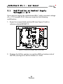
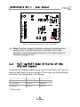
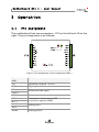
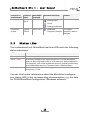
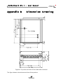
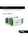
Mix 1
Motherboard for the PCAN-MicroMod
User Manual
Motherboard Mix 1 – User Manual
Products taken into account
Product Name
Model
Item Number
PCAN-MicroMod Motherboard
Mix 1
Including casing and
PCAN-MicroMod
IPEH-002202
The picture on the front page shows the PCAN-MicroMod Motherboard Analog 1 in
the foreground. All other Motherboards have the same design, but differ in port
assignment and labeling.
Product names mentioned in this manual may be the trademarks or registered
trademarks of their respective companies. They are not explicitly marked by “™” and
“®”.
© 2008 PEAK-System Technik GmbH
PEAK-System Technik GmbH
Otto-Roehm-Strasse 69
64293 Darmstadt
Germany
Phone: +49 (0)6151-8173-20
Fax:
+49 (0)6151-8173-29
www.peak-system.com
[email protected]
Issued 2008-09-23
2
Motherboard Mix 1 – User Manual
Contents
1
1.1
1.2
1.3
2
2.1
2.2
2.3
3
3.1
3.2
3.3
4
Introduction
Properties at a Glance
Special Prerequisites for the Operation
Scope of Supply
Configuring the Module
Operation
7
8
10
11
Pin Assignment
Assignment Functions/MicroMod Services
Status LEDs
Technical Specifications
Certificates
11
12
13
14
16
CE
Appendix B
4
5
5
6
Modification on Nominal Supply Voltages >
12 V
Pull-up/Pull-down Circuits of the Digital
Inputs
Measuring Range Extension of the Analog
Inputs
Appendix A
A.1
4
16
Dimension Drawing
3
17
Motherboard Mix 1 – User Manual
1
Introduction
The Motherboards from PEAK-System Technik provide an accommodated environment for the PCAN-MicroMod. This includes input
and output circuits, an aluminum casing, and connectors. This way
you can use the MicroMod e.g. at instrument manufacture, plant
construction, or in the automotive industry.
The motherboard Mix 1 serves common analog and digital requirements and supports temperature measurement.
Note: This manual only refers to the motherboard itself as base
for a PCAN-MicroMod. There is separate documentation regarding the hardware and the software of the PCAN-MicroMod.
1.1
Properties at a Glance
6 digital inputs with following properties:
• Pull-up or pull-down circuit selectable (in 3 groups)
• High state at 5 to 18 V input voltage
• Schmitt trigger behavior, inverting
• Low-pass behavior
• Parallel connection of a frequency input (for each digital
input 0 to 3) for alternative use (e.g. fast changes of state
or countings)
2 temperature inputs for connection of thermistors, measuring
range 0 to 70 °C (32 to 158 °F)
4
Motherboard Mix 1 – User Manual
2 analog inputs with following properties:
• Pull-down circuit
• Measuring range unipolar, 0 to 5 V
• Measuring range extension possible
• Protection against undervoltage and overvoltage
2 digital outputs (“frequency outputs”) with following
properties:
• Fast low-side switches, max. 55 V, 0.75 A
• Short circuit protection
Status LEDs for power supply and digital output
Spring-cage connectors (optionally with screw connection)
1.2
Special Prerequisites for the
Operation
– None –
1.3
Scope of Supply
The scope of supply normally consists of the following parts:
Module with following components: motherboard Mix 1, PCANMicroMod, metal casing
Terminal block connectors for the motherboard
User manual
5
Motherboard Mix 1 – User Manual
2
Configuring the Module
You can customize the motherboard by modifying the hardware.
The following subsections contain descriptions about possible
modifications.
Accessing the Motherboard
In order to carry out the modifications described in the following
you must unscrew the lids of the casing, remove the motherboard
from the casing, and remove the MicroMod, if needed.
Remounting the MicroMod
When you remount the MicroMod, take notice of the white triangular marks on each the motherboard and the MicroMod (upper left
corner, see Figure 1). These marks must align. Another help may be
the orientation of the labeling. With a mounted MicroMod the labels
have the same orientation on both PCBs (not upside down).
Figure 1: Positioning of the MicroMod
6
Motherboard Mix 1 – User Manual
2.1
Modification on Nominal Supply
Voltages > 12 V
If you want to supply the motherboard Mix 1 with a nominal voltage
+Ub > 12 V (usually 24 V), then you must do the following
modification:
1. Equip the unpopulated position D6 (see Figure 2) with a
reference diode BZV55C12.
Figure 2: Position D6 (upper side of the PCB)
2. Replace the 0-Ohm resistor on position R33 (on bottom side of
the PCB, see Figure 3) with a resistor of 1.6 kΩ.
7
Motherboard Mix 1 – User Manual
Figure 3: Position R33 (bottom side of the PCB)
Note: You don't need to consider voltage fluctuations that
might occur. A modification isn't required in that case.
Example: In the automotive field up to 18 V may arise at a
nominal voltage of 12 V.
2.2
Pull-up/Pull-down Circuits of the
Digital Inputs
At delivery all digital inputs are set to pull-up circuits. You can set
them to pull-down circuit in groups. This is done by repositioning
resistors. The assignment is as follows:
*
Digital inputs
Pull-up (+Ub)*
Pull-down (GND)
DI 0
R31 (2.7 kΩ)
R12 (2.7 kΩ)
DI 1 and DI 2
R53 (0 Ω)
R55 (0 Ω)
DI 3 to DI 5
R54 (0 Ω)
R56 (0 Ω)
Default setting
8
Motherboard Mix 1 – User Manual
Attention! Double-check for inadvertent short circuits after
altering the setup, especially at positions R53/R55 and R54/R56.
Figure 4: Positions R31, R53/R55, R54/R56
Figure 5: Position R12 (bottom side of the PCB)
9
Motherboard Mix 1 – User Manual
2.3
Measuring Range Extension of the
Analog Inputs
You can extend the measuring range of each analog input to a
higher maximum voltage than 5 Volts by using a voltage divider. On
shipment of the motherboard the resistor positions R30 and R43 on
the bottom side of the PCB (see Figure 6) are not equipped. By
inserting a resistor Rx with a value calculated with the following
formula the measuring range is extended to the desired maximum
voltage UMB.
Rx =
2 .4 kΩ
( UMB > 5 V)
UMB
−1
5V
Analog
input
Insert Rx on
position
AIn 2
R30
AIn 3
R43
Figure 6: Positions R30 and R43 (bottom side of the PCB)
10
Motherboard Mix 1 – User Manual
3
Operation
3.1
Pin Assignment
The motherboard has two connectors, J1/2 on the left and J3 on the
right. The pin assignment is as follows:
Figure 7: Pin assignment of the motherboard Mix 1
Function label
J1/2
Function
+Ub
Operating voltage 8 - 30 V DC
GND
Digital ground
CAN_L
CAN_H
Differential CAN signal
N/C
Not connected
NTC 0
Temperature measurement NTC
(connection against AGND)
NTC 1
AIn 2
AIn 3
AGND
Analog input
Analog ground
11
Motherboard Mix 1 – User Manual
Function label
J3
GND
Function
Digital ground
GND
FOut 2
Frequency output
FOut 0
DIn 5
Digital input
DIn 4
DIn 3
DIn 2
Digital input, frequency input parallel
DIn 1
DIn 0
3.2
Assignment Functions/MicroMod Services
The motherboard's inputs and outputs are controlled by the
services of the MicroMod. They are set up with PCAN-MicroMod
Configuration, a Windows application coming with the PCANMicroMod. The following table shows the assignment of the
motherboard functions to possible MicroMod services and indicates
special settings (column “Remark”).
Function on
motherboard
Function
label
MicroMod
channels
Digital input,
frequency
input
DIn 0 …
DIn 5
DI 0 … DI 5
MicroMod service(s)
Remark
Digital Input
Digital Function
Rotary Encoder
FI 0 … FI 3
Temperature NTC 0,
measurement NTC 1
Frequency Input
AI 0, AI 1
Analog Input
Curve
12
Parallel to
channels DI 0 to
DI 3
Input values are
anti-proportional
to the
temperature
Motherboard Mix 1 – User Manual
Function on
motherboard
Function
label
MicroMod
channels
Analog input
AIn 2,
AIn 3
AI 2, AI 3
MicroMod service(s)
Remark
Analog Input
Curve
Analog Hysteresis
Frequency
output
3.3
FOut 0,
FOut 2
FO 0, FO 2
For higherPWM and
frequency status
Frequency Output
changes
Status LEDs
The motherboard incl. MicroMod has three LEDs with the following
status indications:
LED
Indication
Power (green)
Power is applied.
DOut 7 (red)
Is directly related to the digital output DO 7 of the MicroMod
and can be configured freely in its function for status indication.
For example, you could implement an error indication with help
of the MicroMod service “Constant Value / Statistic Data”.
Activity (red)
Status of the MicroMod. During normal operation it blinks at a
frequency of 1 Hz.
You can find further information about the MicroMod (configuration, status LED) in the corresponding documentation, e.g. the help
for PCAN-MicroMod Configuration (Windows software).
13
Motherboard Mix 1 – User Manual
4
Technical Specifications
Power supply
Operating voltage +Ub
8 - 30 V DC (±5 %)
Current consumption
Max. 200 mA, typ. 35 mA at 12 V w/o load
Reverse polarity
protection
Yes, ±30 V
Overvoltage protection
±30 V static, ±500 V surge
Ripple 5 V
< 50 mV (Ub = 12 V, 200 mA load)
Ripple analog
< 20 mV
Digital inputs
Switching thresholds
UIH = 4 V; UIL = 3 V, contact or logic level
Input impedance
2.7 kΩ
Open input
Pull-up circuit, optional pull-down circuit (in groups)
Overvoltage protection
±30 V
Low-pass
fg = 7 kHz
Special feature
Frequency inputs of the PCAN-MicroMod parallel (only
DIn 0 to DIn 3)
Digital/frequency outputs
Type
Low-side
Voltage proof
< 55 V
Output current
0.75 A (constant current)
Short circuit protection
Yes, short circuit currents: 1.2 A
Analog inputs
Measuring range
0 to 5 V, extendable
Resolution
10 bits
Source impedance
< 5 kΩ
Overvoltage protection
±30 V
Low-pass
fg = 300 Hz
14
Motherboard Mix 1 – User Manual
Temperature measurement
Reference sensor type
Thermistor EC95F103W (e.g. RS Components part no.
151-237, form factor: bead) 1
Measuring range
0 to 70 °C (32 to 158 °F) corresponding 5 to 0 V
(antiproportional)1
Resolution
±1.0 °C (due to sensor)
CAN
Type
High-speed, typ. 500 kBit/s, setup with MicroMod
Configuration Tool (Windows software)
Noise immunity
Tests
According to IEC 61000 and DIN EN 61 326
Peculiarity surge
±500 V (specification industrial sector: ±1 kV) 2
Peculiarity lineconducted HF
compatibility
10 Veff (specification: 3 Veff)
Measures
Casing size (incl.
connectors)
55 x 68 x 24 mm (3 1/16 x 1 5/8 x 13/16 Inches)
(See also dimension drawing, Appendix B on page 17)
Weight
109 g (3.84 oz.)
Environment
Operating temperature
-40 - +85 °C (-40 - +185 °F)
Temperature for storage -40 - +100 °C (-40 - +212 °F)
and transport
Relative humidity
15% - 90 %, not condensing
1
Other sensor type and measuring range on request
2
This specification could only be fulfilled with ±500 V due to the available space.
Therefore the motherboard should be used with a local power supply.
15
Motherboard Mix 1 – User Manual
Appendix A
A.1
Certificates
CE
16
Motherboard Mix 1 – User Manual
Appendix B
Dimension Drawing
Figure 8: Top view and view of front side with connector
The figure doesn't show the actual size of the product.
17