1
Analog Interface
8.1
8
OVERVIEW
The ADSP-21msp58 and ADSP-21msp59 processors include an analog
signal interface consisting of a 16-bit sigma-delta A/D converter, a 16bit sigma-delta D/A converter, and a set of memory-mapped control
and data registers. The analog interface offers the following features:
•
•
•
•
•
•
linear-coded 16-bit sigma-delta ADC
linear-coded 16-bit sigma-delta DAC
on-chip anti-aliasing and anti-imaging filters
8 kHz sampling frequency
programmable gain for DAC and ADC
on-chip voltage reference
The analog interface provides a complete analog front end for high
performance voiceband DSP applications. The ADC and DAC operate
at a fixed sampling rate of 8 kHz. The inclusion of on-chip anti-aliasing
and anti-imaging filters, 16-bit sigma-delta converters, and
programmable gain amplifiers ensures a highly integrated solution to
voiceband analog processing requirements. Sigma-delta conversion
technology eliminates the need for complex off-chip anti-aliasing filters
and sample-and-hold circuitry.
The ADSP-21msp58 and ADSP-21msp59 contain the same analog
interface—they differ only in the amount of on-chip memory. Refer to
the ADSP-21msp58/59 Data Sheet for detailed analog performance
specifications.
The analog interface of the ADSP-21msp58/59 is operated by using
several data-memory-mapped control and data registers. The ADC
and DAC I/O can be transmitted and received via individual memorymapped registers, or the data can be autobuffered directly into the
processor’s data memory. This autobuffering is similar to serial port
autobuffering, as described in Chapter 5.
8–1
8 Analog Interface
Two ADSP-21msp58/59 interrupts are dedicated to the ADC and DAC
converters. One interrupt is used for the ADC and the other interrupt
is used for the DAC. Interrupts occur at the sample rate or when the
autobuffer transfer is complete.
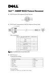
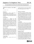
A block diagram of the analog interface is shown in Figure 8.1, and pin
definitions are given in Table 8.1.
16-BIT SIGMA-DELTA ADC
VIN NORM
MUX
ADC
PGA
VIN AUX
ANALOG
SIGMA-DELTA
MODULATOR
ANTI-ALIASING 16
DECIMATION
FILTER
8.0
kHz
1
1.0
MHz
DIGITAL
16
HIGH-PASS
FILTER
8.0
kHz
DECOUPLE
VOLTAGE
REFERENCE
REF FILTER
PROCESSOR
INTERFACE
V REF
BUF
16-BIT SIGMA-DELTA DAC
VOUT P
DAC
PGA
VOUT N
ANALOG
SMOOTHING
FILTER
DIFFERENTIAL
1
1.0
MHz
DIGITAL
SIGMA-DELTA
MODULATOR
16
ANTI-IMAGING
INTERPOLATION
FILTER
1.0
MHz
16
8.0
kHz
DIGITAL
HIGH-PASS
FILTER
16
8.0
kHz
OUTPUT AMP
Figure 8.1 Analog Interface Block Diagram (ADSP-21msp58/59)
8.2
A/D CONVERSION
The A/D conversion circuitry of the ADSP-21msp58/59’s analog
interface consists of an input multiplexer, a programmable gain
amplifier (PGA), and a sigma-delta analog-to-digital converter (ADC).
8.2.1
Analog Input
The analog input is internally biased by an on-chip voltage reference to
allow operation of the ADSP-21msp58/59 with a single +5V power
supply. The analog inputs should be ac-coupled.
An analog multiplexer selects either the NORM or AUX input. The
input multiplexer is configured by bit 1 (IMS) of the
ADSP-21msp58/59’s analog control register (which is memorymapped at address 0x3FEE in data memory). The multiplexer setting
should not be changed while an input signal is being processed.
8–2
16
Analog Interface 8
Pin Name
I/O
Function
VINNORM
I
Input terminal of the NORM channel of the ADC.
VINAUX
I
Input terminal of the AUX channel of the ADC.
Decouple
I
Ground reference of the NORM and AUX channels
for the ADC.
VOUTP
O
Non-inverting output terminal of the differential
output amplifier from the DAC.
VOUTN
O
Inverting output terminal of the differential output
amplifier from the DAC.
VREF
O
Buffered output voltage reference.
REF_FILTER O
Voltage reference external bypass filter node.
VCC
Analog supply voltage.
GNDA
Analog ground.
Table 8.1 Analog Interface Pin Definitions
The ADC PGA may be used to increase the signal level by +6 dB, +20
dB, or +26 dB. This selection is configured by bits 9 and 0 (IG1, IG0) of
the analog control register. Input signal level to the sigma-delta
modulator should not exceed the VINMAX specification listed in the
ADSP-21msp58/59 Data Sheet. Refer to “Analog Input” in the “Design
Considerations” section of this chapter for more information.
An offset may be added to the input of the ADC in order to move the
ADC’s idle tones out of the 4.0 kHz speech band range. This is selected
by bit 10 of the analog control register. The added offset must be
removed by the ADC’s high pass filter; therefore the high pass filter
must be inserted (not bypassed) when the offset is added.
8.2.2
ADC
The analog interface’s ADC consists of a 4th-order analog sigma-delta
modulator, an anti-aliasing decimation filter, and a digital high pass
filter. The sigma-delta modulator noise-shapes the signal and produces
1-bit samples at a 1.0 MHz rate. This bit stream, which represents the
analog input signal, is fed to the anti-aliasing decimation filter.
8–3
8 Analog Interface
8.2.2.1 Decimation Filter
The ADC’s anti-aliasing decimation filter contains two stages. The first
stage is a sinc4 digital filter that increases resolution to 16 bits and
reduces the sample rate to 40 kHz. The second stage is an IIR low pass
filter.
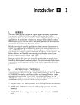
The IIR low pass filter is a 10th-order elliptic filter with a passband
edge at 3.7 kHz and a stopband attenuation of 65 dB at 4 kHz. This
filter has the following specifications:
Filter type:
Sample frequency:
Passband cutoff*:
Passband ripple:
Stopband cutoff:
Stopband ripple:
10th-order low pass elliptic IIR
40.0 kHz
3.70 kHz
±0.2 dB
4.0 kHz
–65.00 dB
* The passband cutoff frequency is defined to be the last point in the
passband that meets the passband ripple specification.
(Note that these specifications apply only to this filter, and not to the
entire ADC. The specifications can be used to perform further analysis
of the exact characteristics of the filter, for example using a digital filter
design software package.)
Figure 8.2 shows the frequency response of the IIR low pass filter.
0
LOG MAGNITUDE – dB
–20
–40
–60
–80
–100
2000
2600
3200
3800
4400
5000
FREQUENCY – Hz
Figure 8.2 IIR Low Pass Filter Frequency Response
8–4
Analog Interface 8
8.2.2.2 High Pass Filter
The ADC’s digital high pass filter removes frequency components at
the low end of the spectrum; it attenuates signal energy below the
passband of the converter. The ADC’s high pass filter can be bypassed
by setting bit 7 (ADBY) of the ADSP-21msp58/59’s analog control
register.
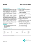
The high pass filter is a 4th-order elliptic filter with a passband cutoff
at 150 Hz. Stopband attenuation is 25 dB. This filter has the following
specifications:
Filter type:
Sample frequency:
Passband cutoff:
Passband ripple:
Stopband cutoff:
Stopband ripple:
4th-order high pass elliptic IIR
8.0 kHz
150.0 Hz
±0.2 dB
100.0 Hz
–25.00 dB
(Note that these specifications apply only to this filter, and not to the
entire ADC. The specifications can be used to perform further analysis
of the exact characteristics of the filter, for example using a digital filter
design software package.)
Figure 8.3 shows the frequency response of the high pass filter.
Passband ripple is ±0.2 dB for the combined effects of the ADC’s
digital filters (i.e. high pass filter and IIR low pass of the decimation
filter) in the 300–3400 Hz passband.
0
LOG MAGNITUDE – dB
–20
–40
–60
–80
–100
0
60
120
180
240
300
FREQUENCY – Hz
Figure 8.3 High Pass Filter Frequency Response
8–5
8 Analog Interface
8.3
D/A CONVERSION
The D/A conversion circuitry of the ADSP-21msp58/59’s analog
interface consists of a sigma-delta digital-to-analog converter (DAC),
an analog smoothing filter, a programmable gain amplifier, and a
differential output amplifier.
8.3.1
DAC
The analog interface’s DAC implements digital filters and a sigmadelta modulator with the same characteristics as the filters and
modulator of the ADC. The DAC consists of a digital high pass filter,
an anti-imaging interpolation filter, and a digital sigma-delta
modulator.
The DAC receives 16-bit data values from the ADSP-21msp58/59’s
DAC Transmit data register (which is memory-mapped at address
0x3FEC in data memory). The data stream is filtered first by the DAC’s
high pass filter and then by the anti-imaging interpolation filter. These
filters have the same characteristics as the ADC’s anti-aliasing
decimation filter and digital high pass filter.
The output of the interpolation filter is fed to the DAC’s digital sigmadelta modulator, which converts the 16-bit data to 1-bit samples at a
1.0 MHz rate. The modulator noise-shapes the signal such that errors
inherent to the process are minimized in the passband of the converter.
The bit stream output of the sigma-delta modulator is fed to the DAC’s
analog smoothing filter where it is converted to an analog voltage.
8.3.1.1 High Pass Filter
The DAC’s digital high pass filter has the same characteristics as the
high pass filter of the ADC. The high pass filter removes frequency
components at the low end of the spectrum; it attenuates signal energy
below the passband of the converter. The DAC’s high pass filter can be
bypassed by setting bit 8 (DABY) of the ADSP-21msp58/59’s analog
control register.
8–6
Analog Interface 8
The high pass filter is a 4th-order elliptic filter with a passband cutoff
at 150 Hz. Stopband attenuation is 25 dB. This filter has the following
specifications:
Filter type:
Sample frequency:
Passband cutoff:
Passband ripple:
Stopband cutoff:
Stopband ripple:
4th-order high pass elliptic IIR
8.0 kHz
150.0 Hz
±0.2 dB
100.0 Hz
–25.00 dB
(Note that these specifications apply only to this filter, and not to the
entire DAC. The specifications can be used to perform further analysis
of the exact characteristics of the filter, for example using a digital filter
design software package.)
Figure 8.3 shows the frequency response of the high pass filter.
8.3.1.2 Interpolation Filter
The DAC’s anti-imaging interpolation filter contains two stages. The
first stage is is an IIR low pass filter that interpolates the data rate from
8 kHz to 40 kHz and removes images produced by the interpolation
process. The output of this stage is then interpolated to 1.0 MHz and
fed to the second stage, a sinc4 digital filter that attenuates images
produced by the 40 kHz to 1.0 MHz interpolation process.
The IIR low pass filter is a 10th-order elliptic filter with a passband
edge at 3.70 kHz and a stopband attenuation of 65 dB at 4 kHz. This
filter has the following specifications:
Filter type:
Sample frequency:
Passband cutoff*:
Passband ripple:
Stopband cutoff:
Stopband ripple:
10th-order low pass elliptic IIR
40.0 kHz
3.70 kHz
±0.2 dB
4.0 kHz
–65.00 dB
* The passband cutoff frequency is defined to be the last point in the
passband that meets the passband ripple specification. (Note that these
specifications apply only to this filter, and not to the entire DAC. The
specifications can be used to perform further analysis of the exact
characteristics of the filter, for example using a digital filter design
software package.)
8–7
8 Analog Interface
Figure 8.2 shows the frequency response of the IIR low pass filter.
Passband ripple is ±0.2 dB for the combined effects of the DAC’s
digital filters (i.e. high pass filter and IIR low pass of the interpolation
filter) in the 300–3400 Hz passband.
8.3.1.3 Analog Smoothing Filter & Programmable Gain Amplifier
The DAC’s programmable gain amplifier (PGA) can be used to adjust
the output signal level by –15 dB to +6 dB. This gain is selected by bits
2-4 (OG0, OG1, OG2) of the of the ADSP-21msp58/59’s analog control
register.
The DAC’s analog smoothing filter consists of a 2nd-order Sallen-Key
continuous-time filter and a 3rd-order switched capacitor filter. The
Sallen-Key filter has a 3 dB point at approximately 25 kHz.
8.3.2
Differential Output Amplifier
The ADSP-21msp58/59’s analog output signal (VOUTP – VOUTN) is
produced by a differential amplifier. The differential amplifier meets
specifications for loads greater than 2 kΩ (RL ≥ 2 kΩ) and has a
maximum differential output voltage swing of ±3.156 V peak-to-peak
(3.17 dBm0). The DAC will drive loads smaller than 2 kΩ, but with
degraded performance.
The output signal is dc-biased to the on-chip voltage reference (VREF)
and can be ac-coupled directly to a load or dc-coupled to an external
amplifier. Refer to “Analog Output” in the “Design Considerations”
section of this chapter for more information.
The VOUTP – VOUTN outputs must be used as a differential signal,
otherwise performance will be severely degraded. Do not use either
pin as a single-ended output.
8–8
Analog Interface 8
8.4
OPERATING THE ANALOG INTERFACE
The analog interface of the ADSP-21msp58/59 is operated with the use
of several memory-mapped control and data registers. The ADC and
DAC I/O data can be received and transmitted in two memorymapped data registers. The data can also be autobuffered into (and
from) on-chip memory where data is automatically transferred to or
from the data registers. In both cases, the I/O processing is interruptdriven: two ADSP-21msp58/59 interrupts are dedicated to the analog
interface, one for ADC receive data and one for DAC transmit data.
(Note: Autobuffering with SPORT1 is not available on the
ADSP-21msp5x processors because this autobuffering channel is used
for the analog interface.)
The ADSP-21msp58/59 must have an input clock frequency of 13
MHz. At this frequency, analog-to-digital and digital-to-analog
converted data is transmitted at an 8 kHz rate with a single 16-bit word
transmitted every 125 µs.
8.4.1
Memory-Mapped Control Registers
Two memory-mapped control registers are used to configure the
ADSP-21msp58/59’s analog interface: the analog control register and
analog autobuffer/powerdown register.
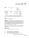
8.4.1.1 Analog Control Register
The analog control register (located at address 0x3FEE in data
memory) is shown in Figure 8.4. This register configures the ADC
input multiplexer, ADC input gain PGA, ADC high pass filter, DAC
high pass filter, and DAC output gain PGA.
The analog control register also contains the APWD bits (bits 5, 6)
which must both be set to ones to enable and start up the analog
interface—always enable and disable the analog interface using both bits
5 and 6. The DAC and ADC begin transmitting data after these bits are
set. Clearing the APWD bits disables the entire analog interface by
putting it in a powerdown state. The APWD bits must be cleared (to
zeros) at least three processor cycles before putting the processor in
powerdown. See “Powerdown” in Chapter 9, System Interface.
The analog control register is cleared (to 0x0000) by the processor’s
RESET signal. Note that bits 10-15 of this register are reserved and
must always be set to zero.
8–9
8 Analog Interface
Analog Control Register
15
14
13
12
11
10
9
8
7
6
5
4
3
2
1
0
0
0
0
0
0
0
0
0
0
0
0
0
0
0
0
0
DM(0x3FEE)
DM[0x3FEE]
OG2 OG1 OG0
ADC Offset
IG1
ADC Input Gain (ADC PGA)
IG0
IMS
ADC Input Gain (ADC PGA)
ADC Input Multiplexer Select
1=AUX input, 0=NORM input
DABY
DAC High Pass Filter Bypass
1=bypass, 0=insert
OG2, OG1, OG0
DAC Output Gain (DAC PGA)
ADBY
ADC High Pass Filter Bypass
1=bypass, 0=insert
APWD
All bits are set to 0 at processor reset.
(Reserved bits 10-15 must always be set to 0.)
IG1, IG0
OG2, OG1, OG0
ADC Input Gain (ADC PGA)
DAC Output Gain (DAC PGA)
Gain
0 dB
+6 dB
+20 dB
+26 dB
IG1
0
0
1
1
IG0
0
1
0
1
Gain
+6 dB
+3 dB
0 dB
–3 dB
–6 dB
–9 dB
–12 dB
–15 dB
Analog Interface Powerdown
0=powerdown, 1=enable
(Set both bits to 1 to
enable analog interface)
OG2 OG1 OG0
0
0
0
0
0
1
1
0
0
1
0
1
1
0
0
1
0
1
1
0
1
1
1
1
Figure 8.4 Analog Control Register
8.4.1.2 Analog Autobuffer/Powerdown Register
The analog autobuffer/powerdown register (located at address 0x3FEF
in data memory) is shown in Figure 8.5. This register enables or
disables autobuffering of ADC receive data and/or DAC transmit
data—autobuffering is enabled by writing ones to the ARBUF (bit 0)
and/or ATBUF (bit 1) bits. When autobuffering is enabled, I (index)
and M (modify) registers are selected in bits 2–11 for the receive
and/or transmit data buffers. See “Autobuffering” in the Serial Ports
chapter for details on autobuffering.
8 – 10
Analog Interface 8
Analog Autobuffer/Powerdown Control Register
15
14
13
12
11
10
9
8
7
6
5
4
3
2
1
0
DM[0x3FEF]
DM(0x3FEF)
ARBUF
ADC Receive Autobuffer Enable
ATBUF
DAC Transmit Autobuffer Enable
ARMREG
Processor powerdown control bits.
(See Chapter 9, “System Interface”)
Receive M register
ARIREG
Receive I register
ATMREG
Transmit M register
ATIREG
Transmit I register
Figure 8.5 Analog Autobuffer/Powerdown Control Register
Bits 12–15 of the analog autobuffer/powerdown register control the
ADSP-21msp58/59’s processor powerdown function, not powerdown
of the analog interface—powerdown of the analog interface only is
controlled by the APWD bits (bits 5, 6) of the analog control register.
The ADSP-21msp58/59’s powerdown function is described in the
“Powerdown” section of Chapter 9, System Interface.
8.4.2
Memory-Mapped Data Registers
There are two memory-mapped data registers dedicated to the analog
interface. The 16-bit ADC receive data register is located at address
0x3FED in data memory. The 16-bit DAC transmit data register is
located at address 0x3FEC in data memory. These registers must be
individually read and written when autobuffering is not in use
(autobuffering automatically transfers the data to and from processor
data memory).
When autobuffering is disabled, data must be transmitted to the
sigma-delta DAC by writing a 16-bit word to the DAC transmit
register (0x3FEC) and data must be received from the sigma-delta ADC
by reading a 16-bit word from the ADC receive register (0x3FED).
8 – 11
8 Analog Interface
8.4.3
ADC & DAC Interrupts
The analog interface generates two interrupts that signal either:
1) that a 16-bit, 8 kHz analog-to-digital or digital-to-analog conversion
has been completed, or 2) that an autobuffer block transfer has been
completed (i.e. the entire data buffer contents have been transmitted or
received).
When one of the analog interrupts occurs, the processor vectors to the
appropriate address:
DAC Transmit interrupt vector address:
ADC Receive interrupt vector address:
0x18
0x1C
These interrupts can be masked out in the processor’s IMASK register
and can be forced or cleared in the IFC register.
8.4.3.1 Autobuffering Disabled
The ADC receive and DAC transmit interrupts occur at an 8 kHz rate,
indicating when the data registers should be accessed, when
autobuffering is disabled. On the receive side, the ADC interrupt is
generated each time an A/D conversion cycle is completed and the
16-bit data word is available in the ADC receive register. On the
transmit side, the DAC interrupt is generated each time a D/A
conversion cycle is completed and the DAC transmit register is ready
for the next 16-bit data word.
Both interrupts are generated simultaneously at an 8 kHz rate,
occurring every 3250 instruction cycles with a 13 MHz internal clock,
when autobuffering is disabled. The interrupts are generated
continuously, starting when the analog interface is powered up by
setting the APWD bits (bits 5, 6) to ones in the analog control register.
Because both interrupts occur simultaneously, only one should be
enabled (in IMASK) to vector to a single service routine that handles
both transmit and receive data. (When autobuffering is enabled,
though, both interrupts should be enabled.)
A simple analog loopback program is shown in Listing 8.1.
8 – 12
Analog Interface 8
{ ADSP-21msp58/59 Analog Interface Loopback Example
}
{
- configures analog interface
}
{
- copies ADC receive data to DAC transmit buffer}
.MODULE/ABS=0/BOOT=0
#define
#define
#define
talkthru;
codec_tx_data 0x3FEC
codec_rx_data 0x3FED
codec_ctrl_reg 0x3FEE
resetv:
irq2v:
hipwv:
hiprv:
spt0tv:
spt0rv:
antv:
anrv:
irq1v:
irq0v:
timerv:
pwrdwnv:
setup:
wait_loop:
JUMP setup; NOP; NOP; NOP;
RTI; NOP; NOP; NOP;
{interrupt vectors ...}
RTI; NOP; NOP; NOP;
RTI; NOP; NOP; NOP;
RTI; NOP; NOP; NOP;
RTI; NOP; NOP; NOP;
RTI; NOP; NOP; NOP;
SI = DM(codec_rx_data);
{read in data from ADC}
DM(codec_tx_data) = SI;
{write out data to DAC}
RTI; NOP;
RTI; NOP; NOP; NOP;
RTI; NOP; NOP; NOP;
RTI; NOP; NOP; NOP;
RTI; NOP; NOP; NOP;
AX1 = 0x0060;
DM(codec_ctrl_reg) = AX1;
IMASK = 0x8;
IDLE;
JUMP wait_loop;
{power up analog interface}
{enable analog receive interrupt}
{wait for interrupt}
.ENDMOD;
Listing 8.1 ADSP-21msp58/59 Analog Loopback Program
8.4.3.2 Autobuffering Enabled
In some applications it is advantageous to perform block data transfers
between the analog converters and processor memory. Analog
interface autobuffering allows you to automatically transfer blocks of
data from the ADC to on-chip processor data memory or from on-chip
processor data memory to the DAC.
An interrupt is generated when an entire block transfer is complete (i.e.
when the data buffer is full or empty). Analog interface autobuffering
operates in the same way as SPORT autobuffering, described in
Chapter 5. Note that data can be autobuffered through the analog
converters or through SPORT0 of the ADSP-21msp58/59.
Autobuffering is not available on SPORT1 of the ADSP-21msp58/59.
8 – 13
8 Analog Interface
Before autobuffering is enabled, separate circular buffers must be set
up in data memory for the ADC receive and DAC transmit data. This
is accomplished by selecting I (index) and M (modify) registers in the
analog autobuffer/powerdown register; see Figure 8.5.
Transmit data autobuffered to the DAC is addressed with the I register
specified in the ATIREG field (bits 9, 10, 11). Receive data autobuffered
from the ADC is addressed with the I register specified in the ARIREG
field (bits 4, 5, 6). The modify (M) registers are specified in the
ARMREG (bits 2, 3) field and ATMREG (bits 7, 8) field. Since the
transfer of ADC and DAC data occurs simultaneously, it is possible to
use the same I register for transmit and receive autobuffering. In this
case, the buffer is shared for both functions and care should be taken
when specifiying a value for the M register.
An autobuffering example program is shown in Listing 8.2.
{ ADSP-21msp58/59 Analog Interface Autobuffer Example
{
- configures analog interface
{
- enables analog autobuffer
{
- receive analog data into a 256 word buffer
{
- transmit analog data from a 256 word buffer
.MODULE/RAM/ABS=0/BOOT=0 auto_example;
.VAR/DM/CIRC buff1[256];
.VAR/DM/CIRC buff2[256];
.VAR/DM flag_bit;
#define codec_tx_data 0x3FEC
#define codec_rx_data 0x3FED
#define codec_ctrl_reg 0x3FEE
#define codec_auto_ctrl 0x3FEF
resetv:
irq2v:
hipwv:
hiprv:
spt0tv:
spt0rv:
antv:
anrv:
irq1v:
irq0v:
timerv:
pwrdwnv:
8 – 14
JUMP
RTI;
RTI;
RTI;
RTI;
RTI;
RTI;
JUMP
RTI;
RTI;
RTI;
RTI;
setup; NOP; NOP; NOP;
NOP; NOP; NOP;
NOP; NOP; NOP;
NOP; NOP; NOP;
NOP; NOP; NOP;
NOP; NOP; NOP;
NOP; NOP; NOP;
switch; NOP; NOP; NOP;
NOP; NOP; NOP;
NOP; NOP; NOP;
NOP; NOP; NOP;
NOP; NOP; NOP;
}
}
}
}
}
{first data buffer}
{second data buffer}
{tracks buffers}
{interrupt vectors ...}
{call autobuffer switch}
Analog Interface 8
setup:
I0 = ^buff1;
L0 = %buff1;
I1 = ^buff2;
L1 = %buff2;
M0 = 0x1;
SI = 0x0;
DM(flag_bit) = SI;
{I0 points to first data buffer}
{I1 points to second data buffer}
{initialize flag register}
{use I1 and M0 for tranmsit}
{use I0 and M0 for receive}
{enable rcv and tx autobuffer}
AY0 = 0x0203;
DM(codec_auto_ctrl) = AY0;
AX1 = 0x0060;
DM(codec_ctrl_reg) = AX1; {power up analog interface}
IMASK = 0x8;
{enable analog rx interrupt}
wait:
switch:
fill_buff1:
fill_buff2:
done:
IDLE;
JUMP wait;
AX0 = DM(flag_bit);
AR = pass AX0;
IF NE JUMP fill_buff2;
SI = 0x1;
AY0 = 0x0013;
JUMP done;
SI = 0x0;
AY0 = 0x0203;
JUMP done;
DM(codec_auto_ctrl) = AY0;
DM(flag_bit) = SI;
RTI;
{wait for autobuffer interrupt}
{check buffer status}
{fill buff2 next time}
{fill buff1 next time}
.ENDMOD;
Listing 8.2 ADSP-21msp58/59 Analog Autobuffer Program
Receive and transmit autobuffering may be independently enabled
and the two interrupts can occur (and be serviced) independently. This
allows the use of different data buffer lengths when autobuffering both
receive and transmit data. It also allows autobuffering to be used on
only one side, receive or transmit, while the other is serviced at the
8 kHz interrupt rate.
8 – 15
8 Analog Interface
8.5
CIRCUIT DESIGN CONSIDERATIONS
The following sections discuss interfacing analog signals to the
ADSP-21msp58/59.
8.5.1
Analog Signal Input
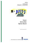
Figure 8.6 shows the recommended input circuit for the
ADSP-21msp58/59’s analog input pin (either VINNORM or VINAUX).
The circuit of Figure 8.6 implements a first-order low pass filter (R1C1).
The 3 dB point of the filter should be less than 40 kHz. This is the only
filter that must be implemented external to the processor to prevent
aliasing of the sampled signal. Since the ADSP-21msp58/59’s sigmadelta ADC uses a highly oversampled approach that transfers most of
the anti-aliasing filtering into the digital domain, the off-chip antialiasing filter need only be of low order. Refer to the ADSP-21msp58/59
Data Sheet for more detailed information.
The ADSP-21msp58/59’s on-chip ADC PGA (programmable gain
amplifier) can be used when there is not enough gain in the input
circuit. The ADC PGA is configured by bits 9 and 0 (IG1, IG0) of the
processor’s analog control register. The gain must be selected to ensure
that a full-scale input signal (at R1 in Figure 8.6) produces a signal level
at the input to the sigma-delta modulator of the ADC that does not
exceed VINMAX (which is specified in the data sheet).
R1
INPUT
SOURCE
±
VINNORM
C1
MUX
C2
VINAUX
C3
DECOUPLE
STAR
GROUND
ADSP-21msp5x
Figure 8.6 Recommended Analog Input Circuit
8 – 16
Analog Interface 8
VINNORM and VINAUX are biased at the internal voltage reference
(nominally 2.5V) of the ADSP-21msp58/59, which allows the analog
interface to operate from a single supply. The input signal should be
ac-coupled with an external capacitor (C2). The value of C2 is determined
by the input resistance of the analog input (VINNORM , VINAUX), 200 kΩ,
and the desired cutoff frequency. The cutoff frequency should be less than
or equal to 30 Hz. The following equations should be used to determine
the values for R1, C1, and C2: R1 should be less than or equal to 2.2 kΩ, C2
should be greater than or equal to 0.027 µF, C3 should be equal to C2.
1
C = 2π f1RIN
2
RIN = input resistance of ADSP-21msp58/59 (200 kΩ)
f1=cutoff frequency ≤ 30 Hz
1
R = 2π f2C2
1
R1 ≤ 2.2 kΩ
20 kHz < f2 < 40 kHz *
C1 =
1
2π f2R1
C3 = C2
* If minimum (< 0.1 dB) rolloff at 4 kHz is desired, f2 should be set to 40 kHz.
8 – 17
8 Analog Interface
8.5.2
Analog Signal Output
The ADSP-21msp58/59’s differential analog output (VOUTP – VOUTN) is
produced by an on-chip differential amplifier. The differential amplifier
will meet dynamic specifications for loads greater than 2 kΩ (RL ≥ 2 kΩ)
and has a maximum differential output voltage swing of ±3.156 V peak-topeak (3.17 dBm0). The DAC will drive loads smaller than 2 kΩ, but with
degraded dynamic performance. The differential output can can be
ac-coupled directly to a load or dc-coupled to an external amplifier.
Figure 8.7 shows a simple circuit providing a differential output with ac
coupling. The capacitor of this circuit (COUT) is optional; if used, its value
can be chosen as follows:
1
C
= 60πRL
OUT
The VOUTP – VOUTN outputs must be used as differential outputs; do not
use either as a single-ended output. Figure 8.8 shows an example circuit
which can be used to convert the differential output to a single-ended
output. The circuit uses a differential-to-single-ended amplifier, the
Analog Devices SSM-2141.
ADSP-21msp5x
C OUT
VOUT P
RL
C OUT
VOUT N
Figure 8.7 Example Circuit For Differential Output With AC Coupling
8 – 18
Analog Interface 8
ADSP-21msp5x
+12 V
0.1 µF
GND
A
7
VOUT
5
V OUT
P
SSM-2141
1
4
VOUT N
GND
A
0.1 µF
–12 V
GND
A
Figure 8.8 Example Circuit For Single-Ended Output
8.5.3
Voltage Reference Filter Capacitance
Figure 8.9 shows the recommended reference filter capacitor connections.
The capacitor grounds should be connected to the same star ground point
as that of Figure 8.6.
VREF
REF_FILTER
+
10µF
BUF
VOLTAGE
REFERENCE
0.1µF
STAR
GROUND
ADSP-21msp5x
Figure 8.9 Voltage Reference Filter Capacitor
8 – 19