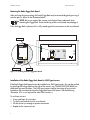
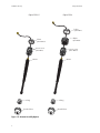
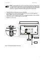
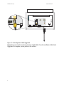
1
Sunny Beam Manual
Sunny Beam
Wireless PV System Monitor
User Manual
U.S. Version 1.1
SBEAM-11:SE0706
i
Sunny Beam Manual
ii
Sunny Beam Manual
Copyright © 2005 SMA America, Inc. All rights reserved.
All rights reserved. No part of this document may be reproduced, stored in a retrieval
system, or transmitted, in any form or by any means, electronic, mechanical,
photographic, magnetic or otherwise, without the prior written permission of SMA
America, Inc.
SMA America makes no representations, express or implied, with respect to this
documentation or any of the equipment and/or software it may describe, including (with
no limitation) any implied warranties of utility, merchantability, or fitness for any particular
purpose. All such warranties are expressly disclaimed. Neither SMA America nor its
distributors or dealers shall be liable for any indirect, incidental, or consequential damages
under any circumstances.
(The exclusion of implied warranties may not apply in all cases under some statutes, and
thus the above exclusion may not apply.)
Specifications are subject to change without notice. Every attempt has been made to
make this document complete, accurate and up-to-date. Readers are cautioned,
however, that SMA America reserves the right to make changes without notice and shall
not be responsible for any damages, including indirect, incidental or consequential
damages, caused by reliance on the material presented, including, but not limited to,
omissions, typographical errors, arithmetical errors or listing errors in the content material.
Revision History
Document Number
n/a
SBEAM-11:SE3605
SBEAM-11:SE0706
Rev. No.
0.1
1.0
1.1
Date
May, 2005
Sept, 2005
Feb, 2006
By
JP
JP
JP
Description
Alpha draft
First Release
Update
SMA America, Incorporated
12438 Loma Rica Drive
Grass Valley, California 95945
Tel 530.273.4895
Fax 530.274.7271
www.sma-america.com
iii
Sunny Beam Manual
IMPORTANT SAFETY INSTRUCTIONS
*SAVE THESE INSTRUCTIONS*
This manual contains important instructions for the Sunny Beam that must be followed during
the installation, operating and maintenance of the Sunny Beam.
The Sunny Beam is designed and tested according to international safety requirements, but as
with all electrical and electronic equipment, certain precautions must be observed when
installing and/or operating the Sunny Beam. To reduce the risk of personal injury and to
ensure the safe installation and operation of the Sunny Beam, you must carefully read and
follow all instructions and warnings in this Installation Guide.
Safety and Hazard Symbols
This symbol is used to call attention to important information that you must have
when installing and/or operating the Sunny Beam. Failure to read and follow
instructions marked with this symbol could result in serious injury and/or damage
to the equipment.
This symbol appears beside instructions and warnings that deal with dangerous
voltages that can injure people who come in contact with them.
Warnings
WARNING: A Warning describes a hazard to equipment or personnel. It calls
attention to a procedure or practice, which, if not correctly performed or adhered
to, could result in damage to or destruction of part or all of the SMA equipment
and/or other equipment connected to the SMA equipment or personal injury.
Warnings may also be accompanied by one or more of the safety and hazard symbols
described above to indicate the type of hazard described therein.
Other Symbols
In addition to the safety and hazard symbols described previously, the following symbol is also
used in this Installation Manual:
This symbol accompanies notes that call attention to supplementary information
that you should know to ensure optimal operation of the system.
iv
Sunny Beam Manual
Warranty
All Sunny Beam units sold in the USA have a one-year warranty, as indicated on the warranty
card included in the shipping container. For warranty coverage, or if you have questions about
the Sunny Beam warranty, contact SMA America at the address, telephone number, or Web
site listed on page iii (to send E-mail, see the Contact section of the SMA America Web site:
www.sma-america.com).
WARNING: All electrical installation must be done in accordance with the
National Electrical Code ANSI/NFPA 70, local building codes and the
requirements of the authority having jurisdiction.
WARNING: Other than the AA batteries, the Sunny Beam contains no userserviceable parts. Always contact an SMA authorized Service Center for
repairs and maintenance other than those detailed in this installation manual.
WARNING: Before installing or using the Sunny Beam, read all of the
instructions and warnings in this Installation Manual.
WARNING: Only the antennas and coax cables supplied with the Sunny Beam
may be used. Any modification to the antennas and/or coax cables will void
the warranty.
WARNING: Changes or modifications not expressly approved by the party
responsible for compliance could void the user’s authority to operate this
equipment.
WARNING: The Sunny Beam uses type RAM rechargeable alkaline batteries
(Accucell 1800). Replace only with the same size and type of batteries or
compatible.
WARNING: The Sunny Beam is designed for indoor use only.
WARNING: Remove the batteries if the Sunny Beam will not be operated for
an extended period of time.
v
Sunny Beam Manual
NOTE: The Sunny Beam relies upon clear radio reception to transfer data. The
radio reception is subject to the influences of the unit’s surroundings such as, other
wireless devices, terrain and the construction materials of the building in which
the device is used. For best results, try to locate the Sunny Beam where it will have
a relatively clear path to the inverter.
NOTE: FCC NOTICE: To comply with FCC Part 15 rules, the system must be
professionally installed to ensure compliance with the Part 15 certification. It is the
responsibility of the operator and professional installer to ensure the only certified
systems are deployed. The use of the system in any other combination (such as colocated antennas transmitting the same information) is expressly forbidden.
NOTE: FCC NOTICE: The FCC label shown in the figure below (left) must be
affixed the the outside of the inverter cabinet. Each inverter that has a radio piggy
back (right) installed must have this label. Place the label on the side of the inverter
near the ratings label.
vi
Introduction . . . . . . . . . . . . . . . . . . . . . . . . . . . . . . . . . . . . . . . . . . . . . . . . . . . . . .1
System Requirements . . . . . . . . . . . . . . . . . . . . . . . . . . . . . . . . . . . . . . . . . . . . . . . . . . . . . . . . . 1
Compatibility. . . . . . . . . . . . . . . . . . . . . . . . . . . . . . . . . . . . . . . . . . . . . . . . . . . . . . . . . . . . . . . 2
Unpacking . . . . . . . . . . . . . . . . . . . . . . . . . . . . . . . . . . . . . . . . . . . . . . . . . . . . . . .2
Installation and Setup . . . . . . . . . . . . . . . . . . . . . . . . . . . . . . . . . . . . . . . . . . . . . . .3
Installing the Radio Piggy-Back . . . . . . . . . . . . . . . . . . . . . . . . . . . . . . . . . . . . . . . . . . . . . . . . . . 3
Mounting the Antenna . . . . . . . . . . . . . . . . . . . . . . . . . . . . . . . . . . . . . . . . . . . . . . . . . . . . . . . . 5
Commissioning . . . . . . . . . . . . . . . . . . . . . . . . . . . . . . . . . . . . . . . . . . . . . . . . . . . .9
Setup . . . . . . . . . . . . . . . . . . . . . . . . . . . . . . . . . . . . . . . . . . . . . . . . . . . . . . . . . . . . . . . . . . . 11
Operation . . . . . . . . . . . . . . . . . . . . . . . . . . . . . . . . . . . . . . . . . . . . . . . . . . . . . . 14
Power Supply . . . . . . . . . . . . . . . . . . . . . . . . . . . . . . . . . . . . . . . . . . . . . . . . . . . . . . . . . . . . . 14
The Home Screen. . . . . . . . . . . . . . . . . . . . . . . . . . . . . . . . . . . . . . . . . . . . . . . . . . . . . . . . . . . 14
Home Screen Display Options . . . . . . . . . . . . . . . . . . . . . . . . . . . . . . . . . . . . . . . . . . . . . . . . . 17
Setup Options . . . . . . . . . . . . . . . . . . . . . . . . . . . . . . . . . . . . . . . . . . . . . . . . . . . . . . . . . . . . . 23
Setup Menu. . . . . . . . . . . . . . . . . . . . . . . . . . . . . . . . . . . . . . . . . . . . . . . . . . . . . . . . . . . . . . . 27
Using the USB Port . . . . . . . . . . . . . . . . . . . . . . . . . . . . . . . . . . . . . . . . . . . . . . . . . . . . . . . . . . 33
Sunny Data Control . . . . . . . . . . . . . . . . . . . . . . . . . . . . . . . . . . . . . . . . . . . . . . . . . . . . . . . . . 33
Troubleshooting . . . . . . . . . . . . . . . . . . . . . . . . . . . . . . . . . . . . . . . . . . . . . . . . . . 41
General Performance . . . . . . . . . . . . . . . . . . . . . . . . . . . . . . . . . . . . . . . . . . . . . . . . . . . . . . . . 41
Inverter Detection . . . . . . . . . . . . . . . . . . . . . . . . . . . . . . . . . . . . . . . . . . . . . . . . . . . . . . . . . . . 44
Specifications . . . . . . . . . . . . . . . . . . . . . . . . . . . . . . . . . . . . . . . . . . . . . . . . . . . . 45
Sunny Beam Manual
Introduction
Introduction
The Sunny Beam allows wireless real-time data monitoring and storage for up to four SMA
Sunny Boy inverters.
Sunny Beam features include:
•
•
•
•
•
•
Large, easy to read LCD
Real-time display of AC power output
Daily and total energy yield displays
Daily energy yields for the current month or last 31 days
Built in solar cell to supplement internal batteries
USB port for data collection on a PC with Sunny Data Control and recharging internal
batteries
System Requirements
The Sunny Beam is a wireless device, therefore it requires that a Radio Piggy-Back board and
antenna be installed on each inverter to be monitored.
The inverters must also be within radio range of the desired location of the Sunny Beam.
Typical ranges for the Sunny Beam are 100 ft. indoors and 500 ft. outdoors. Because radio
transmissions are effected a great deal by terrain, obstacles and other wireless devices, the
actual usable distance will vary from system to system.
For example, the operating range could easily exceed 500 ft. outdoors given the right
conditions such as line of sight between the Sunny Beam and inverter. However, the range
could also be less if there is a structure between the two. The same is true for indoor
installations. Keep this in mind when selecting a location for the Sunny Beam.
5WPP[$Q[
5WPP[$Q[
5WPP[$Q[
5WPP[$Q[
5WPP[$GCO
Figure 1-1 Sunny Beam Supports up to Four Sunny Boy Inverters
1
Unpacking
Sunny Beam Manual
Compatibility
The following SMA inverters a compatible for use with the Sunny Beam:
•
•
•
•
•
•
SB700U
SB1100U
SB1800U
SB2500U
SB3800U
SB6000U
Unpacking
When unpacking the Sunny Beam, make sure that all of the components are present. Save the
shipping container in the event that it ever becomes necessary to return your Sunny Beam to
SMA America.
WARNING: The installation of the Sunny Beam requires access to the inside of
the inverter to be monitored. Lethal voltages are present inside the inverters
when they are operating and installation of the communication card should
only be performed by qualified personnel.
The Sunny Beam shipping container should contain:
•
•
•
•
•
•
The Sunny Beam with attached external antenna
Radio Piggy-Back Board*
Antenna for the inverter*
2 AA rechargeable alkaline batteries (AccuCell AC 1800)
Wall mount bracket
USB Cable
* The number of these items that are included will vary depending on the number of inverters
to be monitored. The Sunny Beam may be purchased with up to 4 antenna kits. Please refer to
the SMA America price list for kit part numbers.
Optional Accessories:
• USB power supply (for recharging internal batteries)
• External antenna mounting kit
2
Sunny Beam Manual
Installation and Setup
Installation and Setup
WARNING: The installation of the Sunny Beam requires access to the inside
of the inverter(s) to be monitored. Lethal voltages are present inside the
inverters when they are operating and the installation of the communication
card should only be performed by qualified personnel.
WARNING: Refer to the Installation Guide for the specific inverter for instructions
on powering down and opening the inverter. This activity should only be
performed by qualified personnel.
NOTE: Because the Sunny Beam’s first task upon start-up will be to detect the
inverters, it is important that the Piggy-Back board(s) be installed before powering
up the Sunny Beam.
Installing the Radio Piggy-Back
After the inverter(s) have been powered down and all residual voltages discharged, the
cover(s) should be removed. (Refer to the Installation Guide for the inverter.)
Groups
The Radio Piggy-Back is capable of operating in any of 16 different groups. The Sunny Beam
comes from the factory preset for group number 1. This should work for most typical
installations. Additional group settings are only required when multiple Sunny Beams will be
used in the same system. The group function is used to determine which inverters each of the
Sunny Beams would communicate with. For example, if there were two Sunny Beams, Sunny
Beam A would communicate with the first 4 inverters on group 1 and Sunny Beam B would
communicate with the other 4 inverters on group 2. The groups are selected by using the DIP
switch on the Piggy-Back board. Verify that the switch is set for group number 1. Only the
number 4 switch should be in the ON position. Refer to the illustration below.
RQ
Figure 1-2 DIP Switch in Group 1 Position
3
Installation and Setup
Sunny Beam Manual
Mounting the Radio Piggy-Back Board
After verifying the group setting, the Radio Piggy-Back may be mounted by gently pressing it
onto the pins as shown in the illustration below.
NOTE: Be sure to support the inverter circuit board from underneath when
mounting the Piggy-Back. Excessive flexing of the circuit board may damage it.
Press the Piggy-Back in place until it is fully seated against the connectors on the circuit board.
$)0SWITCHES
%.3
%.3
3
3
3
3
3
3
6
6
2ADIO0IGGY"ACK
3-!PLUG
Figure 1-3 Installing the Radio Piggy-Back Board
Installation of the Radio Piggy-Back Board in SWR Type Inverters
If the Radio Piggy-Back boards are to be installed in an SWR type inverter, (this can be verified
by checking the ratings label on the side of the inverter, e.g. SWR2500U/SWR1800U) an
additional step must be taken. The SWR type inverters require the cutting of two resistors
located on the circuit board where the Piggy-Back board will mount. See the following
illustration. (This is not required for other SMA inverters.)
To cut these resistors:
•
•
•
•
4
Use a small pair of wire cutters
Cut the lower lead close to the circuit board
Lift the resistor just enough to prevent connection
Repeat for the second resistor
Sunny Beam Manual
Installation and Setup
2ADIO0IGGY"ACK
3-!
372322
68XX
3-!
372"&2
68XX
%.3
6
6
%.3
#
"
!
2EMOVERESISTORS WITH
ONEBLACKRING
RESISTORSCANBE
BROWNORBLUE
Figure 1-4 Resistor Location in SWR Type Inverters
Mounting the Antenna
The antenna provided for use on the inverter comes with a PG type connector for mounting to
the underside of the inverter. The antenna will typically mount in the conduit hole provided for
communications cables.
The PG connector is a PG13.5 type. A PG16 type adapter has also been provided. Inspect the
communications conduit opening and determine if the opening will allow the PG16 adapter to
fit properly. Install the antenna by following the steps and referring to the following illustration.
• Slide the seal-ring onto the antenna from the top, sliding it down the antenna to the base
until it is flush with the bottom of the antenna. Make sure the narrow end of the seal-ring
faces the base of the antenna.
• Slide the pressure screw over the coax and over the seal ring until the small bumps on the
seal ring snap into the notches on the pressure screw.
• Slide the threaded sleeve over the top and down the antenna and thread it onto the pressure screw. Tighten the threaded sleeve until snug. Do not over tighten.
• If required, slide the PG16 adapter over the coax and thread it onto the pressure screw.
Tighten the adapter until snug. Do not over tighten.
• Route the coax through the opening on the underside of the inverter until the pressure
screw sits flush against the inverter
5
Installation and Setup
Sunny Beam Manual
/PTION0'
/PTION0'
LOCKNUT
OPTION0'
ADAPTOR
OPTION0'
LOCKNUT
OPTION0'
PRESSURESCREW
OPTION0'
PRESSURESCREW
OPTION0'
ANTENNA
ANTENNA
SEALRING
THREADEDSLEEVE
Figure 1-5 Antenna Assembly Options
6
SEALRING
THREADEDSLEEVE
Sunny Beam Manual
Installation and Setup
NOTE: To operate effectively, the PG connector for the antenna must be grounded.
It is important that the metal of the PG connector make good contact with the metal
case of the inverter. Make sure that the teeth of the locknut face the metal and that
the locknut is tightened sufficiently to allow good metal to metal contact.
• Thread the locknut onto the pressure screw and tighten.
• Once the antenna is in place, thread the coax connector onto the Radio Piggy-Back
board. Tighten until snug - do not over tighten.
• Check the DIP switch to make sure that it was not changed accidentally during installation.
• Verify that the coax is routed through the inverter safely.
• Replace the inverter cover.
%.3
%.3
3
3
3
3
3
3
6
6
0'CABLEGLAND
COAXIALCABLE
ANTENNA
Figure 1-6 Mounting the Antenna to the Inverter
7
Installation and Setup
Sunny Beam Manual
%.3
%.3
3
3
3
3
3
3
6
6
Figure 1-7 Connecting Coax to Radio Piggy-Back
Repeat this process for the remaining inverters if applicable. Once the installation of the Radio
Piggy-Backs is complete, restore power to the inverters.
8
Sunny Beam Manual
Commissioning
Wall Mounting the Sunny Beam
The Sunny Beam is design to work as a
desktop unit. However, in some
applications, it may be desirable to mount
the Sunny Beam to a wall. A wall-mount
bracket has been provided for this
purpose.
Mount the wall bracket securely to the wall
using appropriate hardware for the wall
material.
Set the top of the Sunny Beam onto the tab
at the top of the wall bracket.
Bring the Sunny Beam down towards the
bottom of the wall mount. Then pull down
on the Sunny Beam enough to clear the
two tabs at the bottom of the wall bracket
and set the two tabs into the slots on the
bottom of the Sunny Beam.
To remove the Sunny Beam, simply
reverse the process.
Commissioning
Navigation
In order to commission, setup and use the Sunny Beam it will be necessary to navigate through
assorted screens and menus. This is accomplished through the use of a rotary push-button type
knob on the side of the Sunny Beam. This knob functions as follows:
Rotate the knob to:
• Move the curser up and down on menu screens
• Increase, decrease values or scroll through menu item settings
• Scroll through the display screens
Press the knob to:
• Enter the menu mode
• Select a highlighted item
9
Commissioning
Sunny Beam Manual
Sunny Beam External Antenna Position
The external antenna on the Sunny Beam has a built-in hinge. Bend the antenna at the hinge
and position it so that it is straight up. This will be the most effective position for most
installations.
NOTE: Do not rotate (other than where hinged), loosen or remove the external
antenna from the Sunny Beam. Operating the Sunny Beam without the antenna
will damage the Sunny Beam and void the warranty.
Installing the AA Batteries
To begin the setup process, install the pair of AA batteries included with the unit. Remove the
battery compartment cover located on the bottom of the Sunny Beam and insert the AA
batteries. Be careful to observe proper polarity.
NOTE: Only the batteries supplied with the Sunny Beam should be used. If it
becomes necessary to replace the batteries in the future, replace with the same
size and type. (AA Rechargeable Alkaline)
NOTE: The Sunny Beam may begin to operate before the batteries are inserted if
exposed to sunlight. The batteries must still be inserted for the Sunny Beam to
function properly. The solar cell is design to help keep the batteries full, but not
energize the entire unit.
NOTE: To make the installation of the AA batteries easier, insert the positive (+)
end of the cell first.
Once the batteries are inserted, replace the battery compartment cover. The Sunny Beam will
turn on automatically and enter setup mode.
10
Sunny Beam Manual
Commissioning
Setup
Set Date and Time
When the Sunny Beam is first powered up it will begin with setting the date and time.
NOTE: This is a good opportunity to become familiar with the operation of the
knob. Notice how the selected item changes as the knob rotates. Once the correct
value is displayed, press the knob to select it.
To set, follow these instructions:
• Rotate the knob so that DAY is highlighted. (Indicated by a box around the entire lineitem)
• Press the knob to select DAY
• Rotate the knob until the proper date is showing
• Press the knob to set DAY
• Rotate the knob so that MONTH is highlighted
• Press the knob to select MONTH
• Rotate the knob until the proper month is showing
• Press the knob to set MONTH
• Repeat this process for the remaining items
• When finished, highlight EXIT and press the knob
4 VOOZ# FBN
4&5%"5&5*.&
%":
.0/5)
:&"3
)063
.*/65&
&9*5
Figure 1-8 Setting the Date and Time
11
Commissioning
Sunny Beam Manual
Sunny Boy Detection
Once the date and time are set the Sunny Beam will automatically begin to search for active
inverters. While the Sunny Beam is searching, the radio frequency, or “group” number is
displayed along with the number of inverters found.
NOTE: The Sunny Beam should be kept a minimum of 10 feet away from the
Sunny Boy during the detection process to avoid overloading the receivers.
4 VOOZ# FBN
4 VOOZ# PZ% & 5& $ 5*0 /
(3061
%&5&$5&%4VOOZ#PZT
Figure 1-9 Sunny Boy Detection Process
12
Sunny Beam Manual
Commissioning
Excluding Inverters
Once the Sunny Beam has finished searching for inverters, it will display the inverters found
and show their type and serial numbers. This screen provides an opportunity to exclude certain
inverters. For example, if the Sunny Beam can detect inverters that are not part of the plant or
if it detects inverters that will not be monitored at this time, the undesired inverters would be
excluded during this step.
To exclude an inverter, rotate the knob so that the inverter to be excluded is highlighted, press
the knob to select the inverter. When excluded, the Sunny Beam will strike-through the
inverter’s information. See the illustration below. If no inverters are to be excluded, select
Proceed to Registration.
NOTE: The Sunny Beam allows manual detection of inverters at anytime so
excluded inverters can be added when desired.
Proceed to Registration: Once any excluded inverters are selected, continue to the registration
process to complete the setup.
Find More Devices: Instructs the Sunny Beam to continue to search for more inverters.
Cancel: Select cancel to exit this process.
Once this process is complete, the Sunny Beam will display the home screen and begin normal
operation.
4 VOOZ# FBN
&9$ -6 % &4VOOZ#PZT
83)94/
83.44/
83)94/
130$&&%503&(*453"5*0/
'*/%.03&%&7*$&4
$"/$&-
Figure 1-10 Excluding Inverters During Startup
13
Operation
Sunny Beam Manual
Operation
Power Supply
The Sunny Beam operates off of the pair of AA batteries inside the unit. These batteries are
recharged by the solar cell on the back of the Sunny Beam, or via the USB port with a powered
USB hub or special USB wall-charger.
Power Level Indication
The power level of the internal batteries is displayed on the home screen in the form of a small
battery cell icon. At 3.30 V the icon indicates “full” and at 2.50 V the icon indicates “empty”.
If the battery voltage falls below 2.60 V, the “P” in the word Power on the display begins to
blink signifying low battery. The Sunny Beam will continue to operate when the “P” is blinking.
If the battery voltage drops below 2.50 V, the Sunny Beam will shut down. The display will
remain blank, but every 10 seconds the Sunny Beam wakes up and checks the battery voltage.
Once sufficient power is available the Sunny Beam will restart automatically.
Recharging the Batteries
The internal batteries are typically kept charged by the solar cell on the back of the Sunny
Beam. For best results, the Sunny Beam should be located where the solar cell will be exposed
to sunlight. If the location of the Sunny Beam is not exposed to sunlight, anticipate placing the
Sunny Beam in direct sunlight from time to time to recharge the batteries.
The batteries may also be charged via the USB port. To charge the batteries via the USB port,
connect the USB cable supplied with the Sunny Beam to the USB port on the side of the unit.
The USB cable then needs to be connected to a USB power source such as a powered USB hub
or the optional USB power supply available from your SMA dealer. Once connected, the
Sunny Beam will display the USB symbol on the display and charge the internal batteries as
needed.
The Home Screen
The Home Screen is what the Sunny Beam will display under normal operating conditions.
There are several options that the Sunny Beam can be set to display on this screen. The Home
Screen can display in text:
•
•
•
•
•
•
•
14
Total power output of the plant and individual inverters
Percentage of P-Limit
Device Type of inverters
Serial Number of inverters
Earnings in desired currency
CO2 Saved
Date and time
Sunny Beam Manual
Operation
The Home Screen can also display the following information in graph format:
•
•
•
•
Daily total plant power output
Daily single inverter power output
Daily total energy yields for the last 31 days or of the current month
Internal battery voltage level
Default View
The Sunny Beam comes set from the factory to display the daily yield and total yield of the
entire plant in the text area. The total plant power for the day is displayed in the graph area.
The same data for the individual inverters can be displayed by rotating the knob.
Scrolling Through Screens
When scrolling through screens, the Sunny Beam shows first the combined output of all
inverters being monitored. Then, by rotating the knob one click, it shows the individual power
outputs for the individual inverters. For example, if there are two inverters, it shows: Combined
power, inverter 1 power out, inverter 2 power out. Then it shows combined energy yield
followed by the individual energy yields for each inverter. This sequence repeats for any of the
parameters that are selected to be displayed.
When the home screen is displayed, any activated parameters will be shown in the black bar
beneath the graph. Each item will be displayed briefly before the Sunny Beam automatically
scrolls to the next item.
NOTE: The graph shows the power output of the plant or individual inverters over
the course of the day. If at any time the Sunny Beam fails to communicate with any
of the inverters, that portion of the graph will be grayed out.
15
Operation
Sunny Beam Manual
$ATE
L8
.P
4IME
'RAPHOF$AILY
/UTPUT0OWER
)NDIVIDUAL
/UTPUT0OWER
1 8
1 8
1 8
U
1 8
3UNNY"EAM
"ATTERY,EVEL
#OMBINED
/UTPUT0OWER
4OTAL$AILY
%NERGY9IELD
4OTAL0LANT
%NERGY9IELD
Figure 1-11 Home Screen Display Details
Auto Scaling
The graph will automatically scale the x and y axis throughout the day depending on power
output. For example, as the power output increases during the morning, the Sunny Beam
rescales the graph automatically so that the peak always remains displayed.
16
Sunny Beam Manual
Operation
Monthly Data
The total power output for each of the inverters is stored for viewing in the Daily Energy Yield
screen. By rotating the knob, the total for each inverter as well as the total for the plant can be
viewed.
L8I
.P
%"*-:&/&3(::*&-%
.BZ
Figure 1-12 Daily Energy Yield
Home Screen Display Options
In addition to the factory set of display options, there are several additional types of
information that can be displayed. The following examples show the different parameters that
are available.
NOTE: Instructions on how to activate each of these options is in the following
section under Data View.
17
Operation
Sunny Beam Manual
Percentage of P-Limit
The power output is displayed as a percentage, calculated from the current output power of
the inverter divided by the maximum output power. The individual inverters are selectable by
rotating the knob.
L8
.P
1 1 1 U
1 Figure 1-13 Percentage of P-Limit of All Inverters
L8
.P
1 1 Figure 1-14 Percentage of P-Limit Individual Inverter
18
1 U
1 Sunny Beam Manual
Operation
Device Type
The Device Types of the connected inverters are displayed in this screen. When an inverter’s
device type number is displayed, its power values are displayed in the black bar beneath the
graph.
L8
.P
U
%&7*$&83.4
Figure 1-15 Device Type Display
19
Operation
Sunny Beam Manual
Serial Number
The serial numbers of the connected inverters will be displayed along with their corresponding
power values. This is helpful in determining the actual inverter being monitored.
L8
.P
%&7*$&4/
Figure 1-16 Serial Number Display
20
U
Sunny Beam Manual
Operation
Earnings
The earnings are displayed in the desired currency. The setting of the currency and the
remuneration is explained in detail in the Coefficients of Balance section of this manual.
L8
.P
5PEBZ
U
Figure 1-17 Earnings Display
21
Operation
Sunny Beam Manual
CO2 Saved
In this screen the amount of CO2 saved by the operation of the plant is displayed in kilograms.
The formula for this is based upon selections made in the Coefficients of Balance setup.
L8
.P
5PUBM
Figure 1-18 CO2 Saved Display
22
U
LH$0
Sunny Beam Manual
Operation
Setup Options
Main Menu
To access the different setup options for the Sunny Beam, begin by going to the Main Menu.
This menu is reached by pressing the knob once while in any of the home level screens. This
section describes the functions of each of the Main Menu items.
4 VOOZ# FBN
. " */ . & / 6
-"/(6"(&
5*.&
$0/53"45
%"5"7*&8
7*&8015*0/4
4&561
&9*5
Figure 1-19 Main Menu
Language: As described earlier, the Language menu allows the user to choose between
English, Spanish or German.
Time: The Time menu allows the user to set the time and date in the Sunny Beam.
23
Operation
Sunny Beam Manual
Contrast
The Contrast menu allows the contrast of the screen to be adjusted for best visibility. There are
separate settings for the upper screen and the lower screen. Adjust for the best view in the
surrounding light conditions.
4 VOOZ# FBN
$ 0 / 53 " 4 5
611&3"3&"$0/53"45
-08&3"3&"$0/53"45 &9*5
Figure 1-20 Setting the Contrast
24
Sunny Beam Manual
Operation
Data View
The Data View menu is used to select which items are to be displayed. The check mark indicates
that the item will be shown on the home screen. Use the knob to select and set the options to
be displayed and then select Exit to return to the main menu.
4 VOOZ# FBN
% "5"7 *& 8
1&3$&/5"(&501-*.*5
%&7*$&5:1&
4&3*"-/0
&"3/&%
$04"7&%
&9*5
Figure 1-21 Data View Menu
25
Operation
Sunny Beam Manual
View Options
The View Options menu allows the interval at which the data is updated to be adjusted.
Data Change Freq.: Sets the interval at which the data on the screen is updated. This can be
set from 5 to 30 seconds.
Data Request Freq.: Sets the interval at which data is requested from the Sunny Boy inverter.
This can be set from 10 seconds to 60 minutes.
Display Off Delay: Sets the amount of time the Sunny Beam will wait during inactivity before
shutting off the display to conserve power.
History: Selects wether the historical data is displayed for the last calendar month (1 M) or last
31 days (31D).
NOTE: These settings greatly effect the overall energy consumption of the Sunny
Beam. For longer battery life, set longer Data Request times and shorter Data
Change and Display Off times.
4 VOOZ# FBN
7 *& 8 0 1 5*0 / 4
%"5"$)"/(&'3&2
%"5"3&26&45'3&2
%*41-":0''%&-":
)*4503:
&9*5
Figure 1-22 View Options Menu
26
T
T
T
.
Sunny Beam Manual
Operation
Setup Menu
The Setup menu allows for further customizing of the Sunny Beam.
4 VOOZ# FBN
4 & 56 1
1-"/5
4&37*$&
&/&3(:.&5&3"%+645.&/5
$0&''*$*&/540'#"-"/$&
3&4&54VOOZ#FBN
&9*5
Figure 1-23 Setup Menu Items
Plant
The plant menu allows changes to be made in the number of inverters being monitored and
the radio frequency being used. The following three items are found in the Plant menu:
Sunny Boy Detection: This will initiate another detection routine in which any of the inverters
on the same frequency or “group” and within range of the Sunny Beam will be detected and
displayed. This routine allows inverters to be added or removed to the list of inverters
monitored by the Sunny Beam. The Sunny Beam can monitor up to 4 inverters at a time. For
monitoring more, see Group below for information on setting up groups of inverters.
Exclude Sunny Boys: Choose this option manually to remove any undesired inverters from the
Sunny Beam’s list. Or, anytime after a detection of inverters is completed, this option is
automatically available and any undesired inverters may also be excluded at that time.
Group: The Group screen allows selection of the operating Group. The Sunny Beam comes set
from the factory on Group number 1. This setting will work for most applications. In the event
of interference, it is sometimes possible to cure it by changing the Group number. It is also
possible to monitor another “group” of inverters using this function. For example, if a system
had 8 Sunny Boy inverters, each with a wireless piggy-back card, the first group of 4 would
27
Operation
Sunny Beam Manual
be set to Group 1. The second set of 4 would be set to Group 2. Then, by changing the Group
number in the Sunny Beam between 1 and 2, each set of 4 inverters could be monitored
separately.
NOTE: Only one group of inverters is monitored at a time. For example, if the
Sunny Beam is set to Group 1, then only those inverters (up to 4) set for Group 1
are monitored. No data is being retrieved or stored for any other group until the
Sunny Beam is set for that Group number.
Service
The Service menu contains items used in troubleshooting and performance related issues.
4 VOOZ# FBN
4 & 37*$&
Figure 1-24 Service Menu
28
%*"(/045*$4
$0..6/*$"5*0/
53"/4.*55*/(108&3
&9*5
4#FBN
Sunny Beam Manual
Operation
Diagnostics
The Diagnostics screen provides information on the communication performance of the Sunny
Beam and can be very helpful in troublshooting communication issues. When this screen is
entered, the Sunny Beam begins transmitting requests for data to the Sunny Boy(s). The Sunny
Beam records the successes and failures of these communication requests as described below.
% *" ( / 0 4 5*$ 4
'JSN X BSF4 # FBN 7FST
1#71#7
1#71#7
4
%&7*$&
-4
-3
7
Figure 1-25 Diagnostics Screen
Firmware SBeam: Displays the current version of the firmware installed in the Sunny Beam.
1.PB, 2.PB, 3.PB, 4.PB: Shows the firmware version for each of the installed piggy-back cards.
Device: Shows the last 5 digits of the Sunny Boy serial number for unit identification.
S, LS, LR: Displays the number of information packets being transmitted and received for
analysis.
S: Displays the number of requests for data being sent by the Sunny Beam to the Sunny Boy.
LS: Displays the number of requests sent by the Sunny Beam to the Sunny Boy that the Sunny
boy did not receive. In other words, the Sunny Boy can not “hear” the Sunny Beam. The Sunny
Beam may be too far away from the inverter. Ideally, this number should remain at zero.
LR: Displays the number of requests that were confirmed by the Sunny Boy but weren’t received
by the Sunny Beam. In other words, the Sunny Beam is having difficulty “hearing” the Sunny
Boy and may be too far from the inverters. Ideally, this number should remain at zero.
29
Operation
Sunny Beam Manual
The Percentages: Displays the success rate of the communication. Ideally this number would
remain at 100% indicating that all requests for data were completed. If this number was 50%,
it would mean that half of the time the Sunny Beam is unable to complete a request for data
with the Sunny Boy. If the number is 0%, it means that the Sunny Beam is unable to
communicate with any of the inverters and needs to be moved closer.
The “transmit arrow” in the center of the screen: This arrow illuminates whenever the Sunny
Beam transmits a request for data.
The Bar Graphs: The bar graphs display the relative field strength of the signal being received
from the Sunny Boys. In other words, it graphically displays how well the radio signal from the
Sunny Boys is being received. Ideally, these bar graphs should light across the entire scale
indicating full strength. This makes it easy to determine if all of the inverters being monitored
are being received equally.
To leave the Diagnostics screen, press the knob.
Communication
The Communication menu is used when setting up the Sunny Beam for use with a PC running
Sunny Data Control.
SBeam: When connected to Sunny Data Control, only the information on the Sunny Beam will
be displayed. (Power output, daily yield, total yield)
Plant: Allows data from the Sunny Boy inverters to be displayed on a PC via Sunny Data
Control. Selecting this mode will allow the information in the inverters and the information in
the Sunny Beam to be displayed.
NOTE: No matter which setting is selected, only data for the entire plant is
recorded. Individual inverter data is displayed, but not recorded.
Transmitting Power
Firmware versions 2.16 and earlier, have an item in the Setup menu called Transmitting Power.
There are two possible settings: norm and test. The power levels for both the inverter(s) and the
Sunny Beam should be set to test. The transmit power for the inverter(s) is set by a command
from the Sunny Beam. To change the power levels, the Sunny Beam will need to be within radio
range of the inverter(s) and the inverter(s) will need to be operating at the time. Be sure to save
the changes when prompted to do so after exiting the menu.
30
Sunny Beam Manual
Operation
Energy Meter Adjustment
The energy meter for each of the Sunny Boys can be adjusted in the Sunny Beam if required.
For example, this would allow an inverter used in a previous system to start out at zero, or
conversely, restore the values if the inverter was off-line for any reason.
& / & 3 ( :. & 5& 3 " % +6 4 5. & / 54
83)94/
83.44/
83)94/
4/
:*&-%
0''4&5
7*&8
4
"$$&15
$"/$&-
Figure 1-26 Energy Meter Adjustment
To adjust an energy meter for an inverter, use the knob to scroll up to the inverter to be
modified. Press the knob to select the inverter. Then rotate the knob until the desired offset is
reached. Press the knob to set it, then scroll to ACCEPT and press the knob to save the setting.
31
Operation
Sunny Beam Manual
Coefficients of Balance
This menu allows the price per kilowatt hour and the type of currency to be selected. This also
determines the formula for the Earnings display. The kilograms of CO2 saved per kilowatt hour
can also be set. The factory default for kg CO2 / kWh is a factor of 1.70.
4 VOOZ# FBN
$ 0 & ''*$ *& / 540 '# " -" / $ &
&"3/*/(L8I
$633&/$:
LH$0L8I
&9*5
Figure 1-27 Coefficients of Balance
Reset Sunny Beam
Resetting the Sunny Beam will restore everything in the Sunny Beam to zero except for the time
and date. All other data will be erased. Select RESET Sunny Beam and there will be a prompt
for confirmation before the Sunny Beam resets itself.
32
Sunny Beam Manual
Operation
Using the USB Port
The Sunny Beam has a built in USB port on the side of the unit. This port may be used to charge
the internal batteries or communicate with a PC using Sunny Data Control. When the USB is
active, a USB symbol will appear on the display.
53"SYMBOL
53"INTERFACE
Figure 1-28 USB Port and Symbol on Display
Sunny Data Control
Setup
The Sunny Beam comes with a CD-ROM which includes a copy of the Sunny Data Control
(SDC) software as well as the driver for the Sunny Beam. Before using the Sunny Beam with a
PC, the SDC software and driver must be installed. Refer to the instructions packaged with the
software for installation and system requirements. Once installation is complete, leave the CD
in the drive so that the driver for the Sunny Beam can also be installed in the next steps.
NOTE: SDC will not communicate with the Sunny Beam unless at least one Sunny
Boy inverter has been detected and registered by the Sunny Beam.
Begin by setting the Sunny Beam to “Plant” as described under Communication on Page 30.
Connect the USB cable to the Sunny Beam and then plug the USB cable into the PC.
The PC will auto-detect the Sunny Beam and then ask for a driver. Simply point the PC to the
CD-ROM drive and it will automatically detect and install the correct driver.
Once launched, SDC will display the overview screen. See the following figure.
33
Operation
Sunny Beam Manual
-AIN
#ONTROL
"AR
#URRENT
0LANT
4REE
$EVICE
/VERVIEW
3CREENS
4ABS
Figure 1-29 Guide to SDC Overview Screen
34
Sunny Beam Manual
Operation
Detecting the Sunny Beam
Once SDC is launched, The next step is to select the proper port for SDC to communicate
through. To set up the port, click on Settings in the main control bar and then under
“Connection By” select Sunny Beam (USB) as shown below. Click OK to exit.
Figure 1-30 Sunny Data Control Settings Window
The next step is to detect the Sunny Beam and the inverters. To do this, click on Detect in the
upper control bar. SDC will begin downloading the device information automatically. This may
take a few minutes to complete. Once completed, click OK to exit.
35
Operation
Sunny Beam Manual
Data Channels
The next step is to set up the Sunny Beam data channels to be viewed. This is done by clicking
on the Data tab at the bottom on the main window in SDC. Then, in the left window called
Current Plant Tree, open the Sunny Beam. Then open the Measuring channels. Drag each of
the memory channels to be monitored into the main SDC window. Refer to the following Figure.
NOTE: If the Sunny Beam is not set to “Plant” mode, only the Sunny Beam will be
detected and only its information displayed. To set the Sunny Beam to “Plant”, see
Communication on page 30.
Figure 1-31 Current Plant Tree Window with Measuring Channels
Download and View Stored Data
Once the channel selection is complete, click on Data and SDC will download the data
automatically. The downloaded data is exported by SDC to Excel. To view the data, click on
Show in the upper control bar. There you will see each of the files of data that can be viewed.
Simply double-click on a file to launch Excel and view the file. It is recommended that the
Macro feature be enabled when viewing the data files.
36
Sunny Beam Manual
Operation
The Data button will download:
• Pac at 10 minute intervals
• Total CO2 offset for the day
• Total Energy for the day
Pressing the Energy button will display the Energy total for the last month/31 days.
NOTE: The daily data collected by the Sunny Beam is only stored in the Sunny
Beam until the beginning of the next day. Therefore, if it is required that the daily
totals be downloaded from the Sunny Beam, it needs to be performed before the
inverters restart the following morning.
Real-Time Data
To view real-time data, click on the Online tab at the bottom of the main SDC window. Then,
right-click in the upper left gray box and select Fade in Devices, and All Devices. SDC will now
show the data for the devices being monitored. Refer to the figure below.
Figure 1-32 Fading in Devices
37
Operation
Sunny Beam Manual
Window Setup
Once the devices are displayed, the channel information for each device can be customized.
It is easier to read the display in SDC if the number of boxes shown is limited to the number of
devices. To do this, click on Settings in the upper control bar. Under Arrangement, set the
number of rows and columns needed. Refer to the following figure.
Figure 1-33 Arrangement of the Device Windows
38
Sunny Beam Manual
Operation
When the proper selections have been made, click OK to exit. Then, if there were two inverters
and the Sunny Beam being monitored, the SDC Device Overview window might look like this:
Figure 1-34 Example of One Window per Device
39
Operation
Sunny Beam Manual
Once the windows are setup, the individual channels can be customized by right-clicking in
the window of the device to be modified and selecting Channel Selection. In the Channel
selection window, individual parameters can be added or removed providing a customized
view for each device if desired. See the following figure.
Figure 1-35 Channel Selection Window
For a complete listing of all of Sunny Data Control’s functions, click on the question mark near
the top left of the SDC window and select Manual.
40
Sunny Beam Manual
Troubleshooting
Troubleshooting
General Performance
Generally speaking, the majority of performance issues with the Sunny Beam will be
communication related, e.g. too far from the Sunny Boy, interference from another appliance,
etc. These issues can be easily overcome by experimenting with the placement and orientation
of the Sunny Beam and its antenna.
Group Settings
In cases where a single Sunny Beam will monitor more than 4 inverters, or is multiple Sunny
Beams will be used, it is necessary to assign each group of 4 inverters a Group Number. For
example, inverters 1 through 4 would be Group 1, inverters 5 through 8 would be Group 2,
and so forth. To select a Group Number on the piggy-back board, simply change the settings
of the DIP switch to the desired group using the following table. On the Sunny Beam, Go to the
Main Menu, Select Setup, then Plant, then Group. In the Group menu the desired group can
be selected. As an added convenience, the Group menu in the Sunny Beam also includes an
image of the proper DIP switch settings for that group.
41
Troubleshooting
DIP switch
Sunny Beam Manual
Group (decimal)
Group (decimal)
0
8
1 (default)
9
2
10
3
11
4
12
5
13
6
14
7
15
Figure 1-36 DIP Switch Settings
42
Sunny Beam Manual
Troubleshooting
Sunny Beam Antenna Orientation
Better performance can sometimes be achieved by reorienting the antenna on the Sunny Beam.
Because the antenna is strongest to the sides as opposed to the ends, it can improve
performance to have the side of the antenna facing the direction of the Sunny Boy. For
example, if the Sunny Boy was located directly above the Sunny Beam, (e.g. on the roof), or
directly below the Sunny Beam, (e.g. in a garage or basement), it might improve performance
to orient the antenna horizontally as shown in the figure below.
!NTENNA0OSITIONED6ERTICALLY
!NTENNA0OSITIONED(ORIZONTALLY
7EAK2ADIO3IGNAL
3TRONG2ADIO3IGNAL
Figure 1-37 Sunny Beam Antenna Orientation
Sunny Boy Antenna Orientation
The same holds true for the Sunny Boy antenna. The antenna on the Sunny Boy can be
reoriented through the use of an optional antenna bracket that can be wall mounted in any
position. This bracket is available through your SMA supplier.
43
Troubleshooting
Sunny Beam Manual
Inverter Detection
All Inverters are not Detected
If after running the detection routine, one or more of the inverters are not detected, try the
following:
• Check that the Sunny Beam is set for the correct Group (channel)
• Check the DIP switch on the communication board in the Sunny Boy to make sure it is set
for the correct Group (channel)
• Move the Sunny Beam so that it is closer to the Sunny Boys
• Make sure that the Sunny Beam is approximately 10 feet from the Sunny Boys while
detecting.
NOTE: Though this may sound counterintuitive, it is possible for the Sunny Beam
to have difficulty communicating if it is too close to the Sunny Boy antenna. This is
caused by the overloading of the receivers in both units. To prevent this, try to keep
the Sunny Beam and Sunny Boys at least 10 feet apart.
44
Sunny Beam Manual
Specifications
Specifications
Parameter
Value
Power Supply
Integrated solar cell, internal batteries,
external power supply
Internal Batteries
(2) 1.5VDC Accucell AC 1800 Rechargable Alkalines
Sunny Beam Operating Temperature
0° to 40°C
Sunny Beam Enclosure
Indoor use only
Sunny Beam Supply Voltage
3 VDC
Radio Piggy-Back Operating Temperature
-25° to 85°C
Radio Piggy Back Supply Voltage
5 VDC
Frequency
917 MHz
USB
1.1
Display
1 x 5 Fold alphanumeric
2 x 6 Fold alphanumeric
Control
Rotary push-button
Languages
English, Spanish, German
Dimensions
3.0H x 5.0W x 7.7D inches
(75 x 127 x 195 mm)
Weight
12.3 oz. / 350 g. (with batteries)
45
Specifications
46
Sunny Beam Manual