1
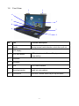
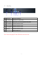
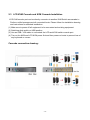
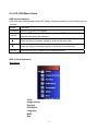
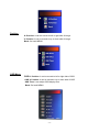
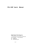
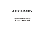
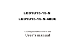
Toll Free: 1-888-865-6888
Tel: 510-226-8368 Fax: 510-226-8968
Email: [email protected]
LCD Drawer User Manual
-1-
This manual, covering various aspects of the equipment such as installation, setup and
cascade, will help you make full use of this widescreen LCD KVM Drawer. Please read this
manual carefully and install and operate the equipment according to the manual to avoid
damage to this product its accessories.
Product package includes following items:
1 * 15.6” LCD KVM Drawer;
1 * AC Power Cord
1 * Rack installation bracket ( one pair )
1 * CD (USER’S manual)
Please check items above. If any item is missing or damaged, please contact your dealer
promptly.
-2-
Table of Contents
1
Introduction …………………………………………………………………………-41.1Overview…………………………………………………………………...…. -41.2 Functions & Features…………………………………… ……………...…..-41.3 Hardware Requirement……………………………………………..….……-41.3.1 Host Requirement………………………………………………....… -41.3.2 Cables…………………………………………………………...….… -41.4 Product Specifications………………………………………………..….…..-51.5 LCD Specifications………………………………………………….…..……-51.6 Front View………………………………………………………….…..……. -61.7 Rear View……………………………………………………………..….…...-7-
2
Installation……………………………………………………………………...……-82.1 Rack Installation……………………………………………………………… -82.2 Standard Installation………………. ………………………………….…… -92.3 LCD KVM Console and KVM Cascade Installation…………… …….…. -102.4 LCD OSD Menu Setup………………………………………………..….… -11-
3
Certificates………………………………………………………………..….….… -14-
-3-
1 Introduction
1.1 Overview
LCD1U15-17 LCD KVM console integrates keyboard, Widescreen LCD display and
touch pad in a drawer type worktable and provides a convenient space-saving operation
mode for KVM switch technology. The cover is an widescreen LCD display, while the base
is keyboard and touchpad. Metal Buckles on the left and right are moved aside to open the
cover. It can be operated once the KVM module is pulled out. Once the operation is
completed, push the KVM module back to the rack.
LCD1U15-17 LCD console is a control device integrating 15.6” widescreen LCD. ,86key keyboard and touchpad mouse. You can access multiple hosts using the LCD console
while saving money and efforts.
LCD KVM console is the best choice to save time and efforts. Since all hosts can be
controlled from a single main control terminal, using the widescreen LCD KVM
Console:(1)avoids the cost of keyboard, mouse and monitor of each host; (2) saves work
space; (3) saves power; (4) saves the trouble of moving from one computer to another.
* For Mac and Sun hosts, USB cable must be used for connection.
1.2
Function & Features
KVM-1501WS LCD KVM display is integrated to a drawer type worktable of 1U height to
facilitate rack installation. Supported resolution up to 1366 x 768, 75Hz. It meets the 1U
height of rack specifications and can be installed into19 inch rack cabinet . No need to
install additional software or hardware.
1.3 Hardware Requirement
1.3.1 Hosts Requirement:
(1) VGA, SVGA or Multisync card
Note: the max. resolution of the integrated widescreen LCD display is 1366x768. Make
sure the resolution of any connected computer does note exceed this resolution.
(2) PS/2 or USB keyboard and mouse port.
1.3.2 Cables
The switch can be connected to hosts using PS/2 or USB connector depending on the
different KVM cable.
-4-
1.4 Product Specifications
Model
LCD1U15-17
Keyboard
86-key Keyboard
Mouse
Touchpad
Local Control
Terminal
Keyboard
PS/2
Mouse
PS/2
Monitor
HD-15 female connector
USB
For USB KB/Mouse
VGA resolution
1366 x 768 @75Hz
Power supply
AC100~240V 50~60Hz
Housing
Metal housing
Weight
13.5Kg
Dimension(W x H x D)
446.4 x 44 x 406.4 (mm)
1.5 LCD Specifications
Model
LCD1U15-17
Size
15.6”
Screen type
TFT
Contrast
500:1
Brightness
250cd/m
Angle of visibility
110°(H), 85°(V)
Resolution
1024 x 768 @75HZ
Color display
16.7M
-5-
15.5Kg
1.6
Front View
1
1
6
3
2
8
4
7
5
NO
Part
Function Description
1
Handle
Moving toward inside direction unlock then pull out
2
LCD display
3
LCD OSD button
4
Keyboard
5
Touchpad
6
LED
LCD Power indicator
7
Mounting bracket
Install into rack cabinet.
8
Lock button
Auto lock / release when lcd pull up and down
LCD button to control Screen Display position and
image setting.
-6-
1.7
Rear View
1
No
2
3
4
5
6
7
Component
Function Description
1
AC Power port
Standard IEC Type AC Inlet
2
Power Switch
Rock switch, turn on/off equipment main power.
3
PS2 Keyboard
Connect to server or KVM.
4
DB15 VGA PORT
Connect to server or KVM.
5
PS2 Keyboard
Connect to server or KVM.
6
USB Port
Connect to server or KVM.
7
PS2-USB Switch
Factory default PS2
Note: Please don't plug PS/2 and USB cables at the same time
-7-
2
Installation
2.1 Rack Installation
Please carry out rack installation according to following procedures:
1.Please switch on your rack and use screws which contain in the package to fix into the
rack.
2.Adjust the rear mounting bracket ( L type ) to fit your rack ,then use screws to fix
Note: 1. Locking nuts provided are used on rack without screw thread.
2. Leave a space of at least 5.1cm wide for ventilation at both sides and 12.7cm at the
back to leave enough sapce for cables.
-8-
2.2 Standard Installation
Please follow the installation drawing and instructions below for standard installation:
* Please Shutdown the Power of Equipment Needs to be Connected
* Please Pay Attention to Earthing of Equipment
A) Plug the VGA , PS/2 or USB port in corresponding ports between the host and KVM
B) Plug AC power Cord
The standard installation is completed, and LCD KVM console can be powered on. Then
power on connected hosts.
-9-
2.3 LCD KVM Console and KVM Cascade Installation
LCD KVM console port can be directly connector to another KVM Switch as cascade to
Perform unified management all connected hosts. Please follow the installation drawing
and instructions for standard installation:
(1) Make sure to power off all equipment to be connected and existing equipment.
(2) Switching slide switch on USB position
(3) Use an USB / VGA cable to connected the LCD and KVM switch console port.
(4) Turn on the KVM and LCD KVM power first and then power on hosts to prevent loss of
any keyboard or mouse.
Cascade connection drawing:
- 10 -
2.4 LCD OSD Menu Setup
OSD Control buttons
LCD OSD can establish and setup LCD display. Setup instructions of four buttons are as
follows:
Button
Functions
POWER Turn on or off the LCD Display
MENU
Activate OSD menu, select a menu and press MENU key to confirm the
selection and enter the submenu.
▲
Press this key to increase setting or scroll up the menu bar
▼
Press this key to Decrease setting or scroll down the menu bar
AUTO
press the auto key to adjust screen display position
OSD Control Operation
Main Menu
Color
Image setting
Position
OSD Menu
Language
MISC
Exit
- 11 -
Color
Contrast:
It can be adjust image get distinct or vague
Brightness: It can be adjust image get dark or bright
Color Adjust: Set favorite color of red, green, and blue
Color Temp: Set color to 9300,6500,5800, Srgb, USER
Back: Go back MENU
Image setting
Clock: Adjust frequency to fill display
Phase: Adjust remove noise and sharpen the image
Sharpness: To mark the image become soft
Back: Go back MENU
- 12 -
Position
H. Position: It can be moved to left or right side of image
V. Position: It can be moved to up or down side of image
Back: Go back MENU
OSD Menu
OSD H. Position: It can be moved to left or right side of OSD
OSD V. Position: It can be moved to up or down side of OSD
OSD Time: It can adjust OSD display time
Back: Go back MENU
- 13 -
Language
English: will display the OSD in English, ( Factory default mode)
French: will display the OSD in French
German: will display the OSD in German
Espanol: Go back MENU
Unsimplified chinese: will display the OSD in Unsimplified chinese
Simplified chinese: will display the OSD in simplified chinese
Japan: will display the OSD in Japan
Misc
Signal Source: D-SUB ( PC only),
Reset: Recall Default value
Back: Go back MENU
Exit
Exit: Go back MENU
- 14 -
3 Certificates
FCC
This product has been tested and is proved to meet requirements of Grade B electronic
devices and specifications of Section 15 of FCC certification. Please observe following two
conditions in operation that:
(1) The equipment will not generate any harmful interruption.
(2) If the equipment is interrupted, it may cause unnecessary operations.
CE
This equipment complies with regulations of EN55022:CLASS B.
RoHS
The whole package including products, packaging materials and documents meet RoHS
equipments.
The company reserves the right to modify product specifications without prior notice and assumes no responsibility for any error which
may appear in this publication.
All brand names, logo and registered trademarks are properties of their respective owners.
Copyright 2008 Synergy Global Technology Inc. All rights reserved.
- 15 -