1
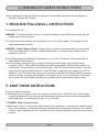
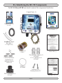
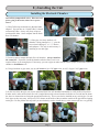
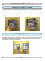
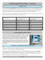
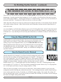
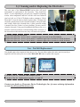
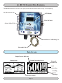
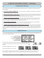
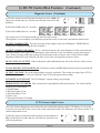
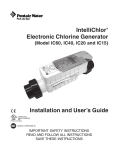
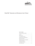
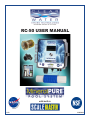
Sustainable solutions for our future RC-50 USER MANUAL with built-in 6/13 CLM-284 Table of Contents Model RC-50 A.) Important Safety Instructions.............................................................................. Page(s) 4 . B.) Identifying the RC-50 Components..................................................................... 5 C.) Tools and Materials Required.............................................................................. 6 D.) Site Survey.............................................................................................................. 6 E.) Installing the Unit.................................................................................................. 7-12 F.) Balancing the Pool’s Water.................................................................................... 13-15 G.) Starting Up the System / Operation Instructions .............................................. 15-16 H.) Proper Procedures of Maintaining a Healthy Pool............................................ 17 I.) Cleaning and/or Replacing the Electrodes / User Maintenance......................... 18 J.) RC-50 Control Box Features................................................................................. 19-23 K.) Troubleshooting..................................................................................................... 23-25 L.) Optional RC-50 Components................................................................................ 25 M.) RC-50 Specifications............................................................................................. 26 Thank you for purchasing the RC-50 MineralPURE/ScaleBlaster unit for your swimming pool. Using new state-of-the-art microchip technology, you have unquestionably the finest ionization system in the world! You can now truly enjoy your swimming pool – the way it was meant to be. You will be swimming in natural “mineral spring” like water. No more red eyes, bleached out swimsuits, and dry itchy skin! Please follow all instructions and keep the “Quick Chart” handy for quick reference! Page 3 A.) IMPORTANT SAFETY INSTRUCTIONS When installing and using this electrical equipment, basic safety precautions should always be followed, including the following: 1. READ AND FOLLOW ALL INSTRUCTIONS. 2. For Model: RC-50 WARNING - To reduce the risk of injury, do not permit children to use this product unless they are closely supervised at all times. 3. For all permanently-installed units intended for use on 15 or 20 ampere, 125 through 240 volt, single phase branch circuits WARNING - Risk of Electric Shock. Connect only to a branch circuit protected by a ground-fault circuit-interrupter (GFCI). Contact a qualified electrician if you cannot verify that the circuit is protected by a GFCI. 4. (For all permanently installed units intended for use on 15 or 20 ampere, 125 through 240 volt, single phase branch circuits.) The unit must be connected only to a supply circuit that is protected by a ground-fault circuitinterrupter (GFCI). Such a GFCI should be provided by the installer and should be tested on a routine basis. To test the GFCI, push the test button. The GFCI should interrupt power. Push the reset button. Power should be restored. If the GFCI fails to operate in this manner, the GFCI is defective. If the GFCI interrupts power to the unit without the test button being pushed, a ground current is flowing, indicating the possibility of an electric shock. Do not use this unit. Disconnect the unit and have the problem corrected by a qualified service representative before using. 5. SAVE THESE INSTRUCTIONS. 6. (only on metal enclosures) A wire connector is provided on this unit to connect a minimum No. 8 AWG (8.4 mm²) solid copper conductor between this unit and any metal equipment, metal enclosures of electrical equipment, metal water pipe, or conduit within 5 feet (1.5 m) of the unit. 7. DANGER - Risk of electric shock. Install at least 5 feet (1.5 m) from all metal surfaces. As an alternative, a spa may be installed within 5 feet of metal surfaces, if each metal surface is permanently connected by a minimum No. 8 AWG (8.4 mm²) solid copper conductor to the wire connector on the terminal box that is provided for this purpose. Page 4 B.) Identifying the RC-50 Components The RC-50 MineralPURE unit should contain all the components listed below. Control Unit (1) Copper Test Kit (1) CLA-41 Users Manual (1) ScaleBlaster Signal Wire (60ft.) 12” Zip Ties (3) RC-50 Quick Chart Card (1) Electrode (1) CLE-11 Threaded Male Adapters (2) CET-0008 2”-1 1/2” Reducers (2) CET-0607 Control Unit Mounting Brackets (4) Mounting Bracket Screws (4) O-Ring (1) CET-0648 Enclosure Lid Securing Screws (2) Flow-Cell Chamber (1) CET-0647 Warranty Card (1) Page 5 C.) Tools and Materials Required • Bullet Level • Channel Lock Wrench • Conduit Connector, ½” Straight • Conduit, Flexible/Electric hookup cable • Crescent Wrench • Drill & Drill Bits • Hacksaw or Pipe Cutter • Hammer • PVC Cement • PVC Cleaner/Primer • Screwdrivers, Flat & Phillips • Screws & Anchors • Teflon Tape or Liquid Teflon • Utility Knife • Voltage Meter • Wire Stripper • Other tools may be required D.) Site Survey The RC-50 MineralPURE/ScaleBlaster unit should be installed at the pool’s pump and filter area. You will need to locate a place to mount the RC-50 control box on a wall and within 10 feet or so of where you will install the electrode chamber and ScaleBlaster signal coil on the return line of your pool equipment. This location will also need to be within 6 feet of an electrical source. Control Box Location Power Source Within 6 feet ScaleBlaster signal cable within 10 feet Electrode chamber within 10 feet Page 6 E.) Installing the Unit Installing the Electrode Chamber Turn off the pump and all valves. Disconnect all power going to the motor, timer box or power source. 1.) Wrap Teflon tape around the two threaded male adapters. You can also use “Liquid Teflon” a thread sealant with Teflon. Always use plenty of tape to avoid possible leaks. Screw adapters into the black flow cell chamber. 2.) If the pipe size where the flow-cell chamber is being installed is 1 ½”, glue the two reducer bushings (2” x 1 ½”) into the male adapters. This step is not necessary if installing on two-inch pipe. 3.) Locate a space to mount the black flow-cell chamber. Always install on the return line. If possible, install the chamber after the filter, but it is not required if there is not enough space. If necessary, you can re-pipe an entire section to allow proper room for the electrode chamber or ScaleBlaster coil. 4.) Using a hacksaw or pipe cutter, cut out a 6”section of pipe if 2” pipe exists, or 6 ½” of pipe if 1 ½” pipe exists. 5.) In the area where the pipe was cut out, mount the black flow-cell chamber horizontally to avoid possible air pockets. In other words, make sure the black flow cell is angled downward, so that when the electrodes are screwed into the chamber, the wire connections are facing the ground and not the sky. The tee can also be installed on any vertical pipe. Do not force pipes as they may snap. Always use PVC cleaner on the inside of the tee and the outside of the pipe before slapping on the glue. Do not perform this step until you are absolutely ready to install the tee, as the cement will cure very quickly. Page 7 E.) Installing the Unit (Continued) 6.) Seat the “O” ring in the electrode jar and hand tighten onto the black flow-cell chamber, no Teflon tape or wrench required! Choosing a power source The RC-50 unit will automatically detect 110 or 220VAC and no internal adjustments are required. When choosing a power source, choose a source that turns on and off with the pump motor. It is very important that the unit turn off when there is no water flowing past the electrodes. The ideal source is the timer box. If no timer box exists, the unit can use the pump motor as its power source. ATTENTION: YOU MUST FOLLOW ALL APPLICABLE LOCAL, STATE, NATIONAL, OR INTERNATIONAL CODES WHEN INSTALLING THIS EQUIPMENT. A CERTIFIED ELECTRICIAN MAY BE REQUIRED FOR THIS PART OF THE INSTALLATION. Mounting the Control Box Keep the protective clear plastic sheet on during installation to stay clear of scratching the unit. 1.) Install the four mounting brackets using the enclosed screws to the back of the control box. Page 8 E.) Installing the Unit Mounting the Control Box (Continued) (continued) 2.) Install the four mounting brackets using the enclosed screws to the back of the control box. Mount the control box to the wall allowing for the electrode and coil wire to reach prospective locations. Remember the ScaleBlaster wire has to reach the area of the pipe where the coil will go and return back to the control box. Hold the control box up to the wall or surface to where it will be mounted and mark the four screw holes. Using a bullet level will ensure the control box is straight. Attach the control box to the wall according to the wall material using approved mounting hardware for that material, i.e. wood screws, mollys, concrete screws, or anchors. Installing the K-Flex conduit 3) The control box in equipped with a k-flex conduit connector for attaching to the electrical power source. Run conduit to the control box either from the pump motor or timer box, we recommend using the timer box. Please refer to the conduit manufacturer’s instructions, your local state building codes, and electrical codes for the details on proper installation of the k-flex conduit. Page 9 E.) Installing the Unit (Continued) Connecting the timer box to the control box 4) Below is an example of connecting the control box to a timer box. In this example an Intermatictm timer box is used. Although most timer boxes are similar they are not exactly the same, please take care when using the provided information. 230 VAC Operation: Connect the black (3 stranded) wire cable to the 230 VAC timer box by splicing the 3 wires and connecting the black and white wires to the LOAD side on the timer box. It makes no difference which colored wire goes to the two load screws. Connect the green wire to GROUND. When installed properly, the unit should come on and off when the pool pump goes on and off. 115 VAC Operation: Connect either the white wire or the black wire to the LOAD side on the timer box. It makes no difference which colored wire goes to the two load screws. Connect the green wire to ground. When installed properly, the unit should come on and off when the pool pump goes on and off. Connecting the pump motor to the control box 5) Disconnect the back plate to the motor where the electrical connections are. You will notice two connections where the power source comes in and is connected. Connect the MineralPURE’s power cable (black, white and green) to the same as the motor’s connections. If connected properly, the unit should come on and off with the motor. Page 10 E.) Installing the Unit (Continued) Connecting the control box to the electrical source 6.) A small flat head screw driver is required for installation. Once the wiring is run through the conduit, attach the wires to the terminal block located on the inner left side of control box. Attach the black wire to the terminal marked LINE, attach the white wire to the terminal marked NEUTRAL, and finally attach the green wire to the terminal marked GROUND. Refer to the wiring diagram located in this section. Optional wire clamp is provided to help secure the wire in place. Attach the face plate to the enclosure and insure that the installed wiring does not interfere with the circuit board attached to the face plate. All trademark names are property of their respective companies. To ensure the maximum NEMA 4 rating, please use the included screws (Enclosure Lid Securing Screws (2)) in the top right and bottom right holes on the lid of the unit once it has been shut and locked in place with the lid latch. Connecting the electrode cable 7.) Connect the two electrode wires (inside the gray colored jacket) to the electrode connectors on the bottom of the electrode jar. It does not matter what wire is connected to the electrode terminals. Make sure they do not touch each other. These connectors are weatherproof and there is no need to cover them. Page 11 E.) Installing the Unit (Continued) Wrapping the pipe with the ScaleBlaster signal cable PVC, CPVC, or PEX PIPE INSTRUCTIONS 1.) Insert the pre-stripped end of the signal cable into one of the two signal terminals and tighten. 2.) Route the signal cable to the inlet pipe. Hold cable parallel and next to the pipe. 3.) Wrap one of the cable ties tightly so that the signal cable is secured to the pipe. (Figure A) 4.) Wrap the loose end of the signal cable securely around the pipe - in any one direction. Wrap the pipe until you reach 40 wraps. 5.) Make sure the wraps are flush against one other, wrapped tightly and not overlapping. 6.) Wrap a second cable tie at the end of the wrappings securing the signal cable tightly. (Figure B) 7.) Route the loose end of the signal cable back to the power box. Trim excess cable to length. 8.) Carefully strip the outer plastic shield form the end of the signal cable leaving 1/4” to 3/8” of bare cable. Twist the bare cable and insert the end in the other terminal post on the power box and tighten the receptacle post. Page 12 F.) Balancing the Pool’s Water Before turning on the system, it is imperative that the pool’s water be clear and balanced properly. Without proper balancing, the unit may not perform properly. Previous Sanitizer Use If the previous sanitizer used was Baquacil, you will need to remove every drop of it, as Baquacil is not compatible with any other sanitizer including MineralPURE. The best way to remove it is to drain the pool completely and refill with fresh water. You should also change the sand in the filter, acid wash the cartridges or change the DE in a DE filter. Consult a professional first if draining the pool. Contact your dealer or Clearwater Enviro Technologies, Inc. for more assistance. If the pool was using an automatic chlorine generator (where salt is added to make chlorine at the site), the water should be drained at least 3/4 of the way and refilled with new water. Usually the TDS level is very high and should be lowered. If the pool was using chlorine, it is all right to go ahead and install the MineralPURE, as the two work together fine. In fact, some chlorine should be in the pool until the system takes over. Proper Circulation Make sure the filtration system and circulation is good. Check the filter to make sure it is cleaned or backwashed properly. The filter pressure gauge should give you an indication right away. If the sand in a sand filter is several years old, you may want to change it. For cartridge filters, check the canister inside to make sure the polyester fabric or corrugated paper is in good shape. If you have a DE filter, change the DE. Good circulation is important because you will no longer be dumping a lot of chlorine in the pool to “cover-up” a bad filtering system. Make sure the skimmer basket is empty and the strainer basket at the pump. This is very important. If you have a pool sweep or vacuum, continue using it as this helps on circulation. Chlorine Always make sure there is some chlorine in the pool when first starting up the system, as it may take a few days to fully “ionize” a pool. Never add granular chlorine (like HTH) directly to the pool with the MineralPURE unit. Always make sure the water is clear before installing the ionizer by using chlorine. The MineralPURE unit itself will not clear up cloudy water. Page 13 F.) Balancing the Pool’s Water (Continued) pH Reading Must be Between 7.2 and 7.8 The most important factor is in water chemistry is the pH reading. It should be kept between 7.2 and 7.8 at all times. If the pH gets too high, MineralPURE’s ions loose their effectiveness and can fall out of solution. Always get the pH on the lower side – 7.2 to 7.4 for best results. This is standard water chemistry. If the pH is above 7.8 - Using an acid demand test with your regular test kit, determine the amount of muriatic acid needed to lower the pH down to 7.2. Add the acid and check a few hours later to make sure it is in the correct range. If the pH is under 7.2 - Using a base demand test with your regular test kit, determine the amount of soda ash needed to raise the pH to at least 7.2. If the pH tends to go down all the time, add enough soda ash to raise the pH to 7.8 Tips on balancing the pH - Test the pH at least once a week or after a heavy rainstorm. When adjusting the pH, don’t wait fort the pH to reach 8.0 before adding acid. Go ahead an add a little acid if the pH is over 7.6. If you use the nonchlorine shock as an oxidizer, this will lower the pH and may eliminate acid use completely. Total Alkalinity Maintain the total alkalinity between 80-120. This should be tested at least once a month. If the total alkalinity is under 80ppm - Raise the total alkalinity by adding sodium bicarbonate (baking soda). Consult chart with your test kit for the amount needed (based on pool size). If the total alkalinity is over 120ppm - Lower the total alkalinity by adding muriatic acid. Consult chart with your test kit for the amount to add. Calcium Hardness The calcium hardness level should be between 150-350ppm. If the reading is well over that, the pool should be partially drained and refilled with fresh water. If the reading is under that, chances are the pool was filled with softened water. Calcium chloride should be added to the pool. 1 1/4 lbs will raise the calcium hardness by 10ppm per 10,000 gallons. Cyanuric Acid Cyanuric acid is not required with the MineralPURE unit. If the reading is over 150ppm, the pool should be partially drained and refilled with fresh water. Total Dissolved Solids The MineralPURE unit requires some conductivity in the water for ionization to take place. A high TDS level can cause cloudiness and the unit not to work efficiently. The TDS level should be between 300 and 2000 ppm. The TDS reading can be obtained at any pool store. If the reading is below 300ppm - To raise the TDS level, you would need to add one pound of regular salt to raise the TDS by 12ppm per 10,000 gallons. You should only do this if you are unable to obtain the desired ion level in the pool because of a low TDS (see chapter later in this manual). Always consult your dealer or Clearwater with help in this matter. If the reading is over 2000ppm - To lower the TDS level, you should partially drain and refill with fresh water. This is standard pool water chemistry. If the unit is being installed on a saltwater pool, the unit will work without any adjustments and there is no need to lower the TDS level. Page 14 F.) Balancing the Pool’s Water (Continued) Copper Level Before installing the MineralPURE unit, the copper level should be tested. There may be readings of copper sulfate in the water from leached copper piping or from a copper based algaecide. Correct the problem by either locating the copper pipe (usually next to a water heater) and balancing the pH, or eliminating any algaecides completely. Shock the pool with an extra heavy dose of chlorine to get rid of the algaecides. If using the Copper/Silver electrode CLE-42 or CLE-44, the table below will allow you to lookup the calculated silver content in your water based upon measured copper levels. Reading using the CLA-41 Copper Calculated Silver Level if using Test Kit in PPM the CLA-42 90/10 copper/silver electrodes in PPM 0.05 0.0056 0.10 0.0111 0.15 0.0167 0.20 0.0222 0.30 0.0333 0.50 0.0556 0.70 0.778 1.00 0.1111 Calculated Silver Level if using the CLA-44 80/20 copper/silver electrodes in PPM 0.0125 0.0250 0.0375 0.0500 0.0750 0.1250 0.1750 0.2500 G.) Starting Up the System When all of the above steps have been completed, it is time to start up the system. Open all valves and turn the power on. Check for water leaks and all electrical connections for proper and firm connections. Remove the clear protective sheet from the control unit. When starting the system, the Clearwater Enviro Technologies, Inc. logo should first appear, followed by a three-digit number. To get better acquainted with the unit, turn the control knob counter-clockwise till the unit reads “OFF” and read through the section “RC-50 control box features. Setting the Control Knob to the Desired Level Once you have obtained the desired reading, the setting will most likely remain at that value the entire season, or close to it. The trick is getting the desired reading quickly. By turning the control knob clockwise, the unit will read a three-digit number. These are actually milliamp (mA) readouts and go from 005 to 600 in 5 mA increments. If the readout does not go all the way to 600, chances are the TDS level is not over 300 or so. Do not cause any alarm or add salt to the pool unless you are not able to obtain the desired ion level (more in this section to follow). Page 15 G) Starting Up the System (continued) THE DESIRED ION LEVEL IN THE POOL IS 0.2 – 0.3 There are a lot of factors that can effect the rate the MineralPURE will produce the ions (see section in Troubleshooting). In order to get the desired reading of 0.2 to 0.3 quickly, you will need to set the unit to its maximum current output (600mA). Turn the knob clockwise to reach this setting. Again, if you can’t reach 600, do not worry at this time. Eventually, the TDS level will rise as will your readout. Other factors that effect the level ions are produced are keeping the pH under 7.8; the number of hours the filter runs, and the setting of the unit. Other factors include water temperature and the amount of algae/bacteria already in the water. As a rule of thumb, it will take about 24 hours to get a pool of 10,000 gallons fully “ionized” and to the desired level of 0.2-0.3 . So if your pool is 20,000 gallons, it may take two full days of running “around the clock” to reach this level. If you run the pool 8 hours a day (the normal time) it would take six days to reach the desired level. Using the MineralPURE Ion Test Kit Included with every unit is an Ion Test Kit. The easy-to-use instructions are located on the inside cover of the lid. Please follow those instructions carefully, as the reading you get is most important in how you set the MineralPURE control knob. When using this test kit, make sure you wait 3 minutes for the test to develop and look down into the tube, not from the side. There is a reading or color match for 0.2 and one for 0.3 on the enclosed chart. Ideally, we would like the readings to be anywhere in that area. Once the Desired Level is Obtained Once the desired level is obtained, you will need to find a setting point on the control box where the ion readings will remain in that range of 0.2 and 0.3 . The biggest factor is water temperature. As a rule of thumb, if the pool is 10,000 gallons, the reading on the control box should be around 75-100. It may be lower in cooler climates, or higher in warmer climates. Someone in Maine may keep the level at 25, while in Florida it may be 125. A 20,000-gallon pool may need a reading of 150 to 200. A 50,000-gallon pool may need a reading of 375 to 500 or so. This is also based on running the system 8 hours a day. It is all proportionate. So if the pool ran 24 hours a day, the settings would be 1/3 that. When you lower your setting, it is best to test on a daily basis. If the readings continue to go up, lower the setting and retest the following day at about the same time. If the reading goes down, turn the control knob up some, and test again the next day. Eventually you will find the proper setting. Once you do, the setting will stay near that the entire season. If your pool is open year round, like in Florida, you will have a lower setting in the winter and a higher setting in the summer. Page 16 H.) Proper Procedures of Maintaining a Healthy Pool INCLUDED WITH THIS PACKAGE IS A “QUICK CHART” THAT GIVES YOU THE BASICS OF MAINTAINING A PROPER POOL. PLEASE REFER TO THAT SHEET WHENEVER POSSIBLE. IF YOU EVER HAVE ANY QUESTIONS, CONTACT YOUR DEALER OR CLEARWATER ENVIRO FOR ANY ASSISTANCE. • Keep the pH between 7.2 and 7.8 • Keep total alkalinity between 80-120ppm • Maintain Ion level between 0.2 and 0.3 ppm • Maintain normal pool maintenance – keep filter cleaned, empty baskets, etc. • Add an occasional oxidizer Adding an Occasional Oxidizer An occasional oxidizer is necessary to burn off body oils, suntan lotions, and particles that get into the water and can cause cloudiness. Always add an oxidizer whenever the water loses its “sparkle”. Don’t wait for the water to get cloudy, or an extra dose will be required. There are several oxidizer options: Non-chlorine shock - Add one (1) pound of potassium monopersulfate (non-chlorine shock) per 10,000 gallons once a week during the warm weather season, less frequently during the cooler weather, or when the water loses its “sparkle”. You may also want to add some non-chlorine shock after a rainstorm if the pool was left uncovered. These are available in most pool stores, or at Leslie’s Swimming Pool Supplies (1-800-537-5437) ask for “Fresh ’N Clear”. Household bleach - Add two (2) quarts of regular household bleach per 10,000 gallons once a week. You may also use liquid chlorine – but only ½ the amount. This small amount will dissolve rapidly and you will have chlorine-free water in a few minutes. Tablet in skimmer - Add a 3” Trichlor tablet in the skimmer for continuous oxidizing. The reading will be so low that it won’t be detectable. This is ideal for pools with heavy swimmer use or if the homeowner is away often. Add ozone to your system - By adding a corona discharge ozone generator to your system, you can virtually eliminate adding any oxidizers to your pool. Contact your dealer for more information. Ionizers are designed for supplementary disinfection and therefore are intended for use with appropriate residual levels of EPA registered disinfecting chemicals. Specific residual levels of EPA registered disinfecting chemicals may be required by the regulatory agency having authority. WARNING: Excessive amounts of Copper may cause staining of pool and spa surfaces Add a Sequestering Agent for Marcite/ Gunite Pool If your pool is made of a white marcite or gunite finish, we strongly recommend you add a sequestering agent to prevent any type of staining in the pool. There are two types we recommend: - Pool Stain Treat by United Chemical (800) 524-5550 - Jacks Magic (800) 348-1656 These products or ones similar are available in all pool stores worldwide. Page 17 I.) Cleaning and/or Replacing the Electrodes The only part of the MineralPURE Ionizer that will need maintenance or replacement is the electrodes. They should last about 1-5 years depending on your pool size, length of swimming season, water temperature and how well the water was balanced (ion level, pH, etc.). If the LCD display reads a warning to “Check Electrodes”, it may be time to clean or replace them. To inspect the electrodes, simply unscrew the electrode chamber with your hands and visually inspect the electrode bars. A blue greenish coating is normal, however, if there is a heavy buildup, you may need to clean the electrode. Using an old toothbrush and lemon juice or a muriatic acid/water solution, scrub the buildup off the electrode. If the electrodes are thin and worn out, they will need to be replaced. Electrode Reordering Information: Replacement Electrode - Part # CLE-11 - residential copper electrode for the RC-50 Model. Replacement Electrode - Part # CLE-42 (90/10) - residential copper/silver electrode for the RC-50 Model Replacement Electrode - Part # CLE-44 (80/20) - residential copper/silver electrode for the RC-50 Model Ion – Test Kit Replacement You should replace the reagents at least once a year. You can either replace the entire test kit (exactly as supplied in the box when you received the MineralPURE unit) or replace the reagents. Order # CLA-41 Order # CLA-42 MineralPURE complete test kit Replacement reagents “A” and “B” Contact your dealer or Clearwater Enviro Technologies, Inc. for more ordering information or visit www.ElectrodeWarehouse.com Page 18 J.) RC-50 Control Box Features The RC-50 control box has one LCD display screen and one control knob for easy to use simplicity. RC-50 Control Unit LCD Display Clear Lid Latch Output Adjust Knob ScaleBlaster Coil Binding Post Electrode Cable Main Screens Output Current Indicator Splash Screen Normal Operating Screen Electrode Status Icon Coil Status Icon Revision Number Page 19 Scrolling Status Messages J.) RC-50 Control Box Features (Continued) Output Current Indicator This value indicates the output current flowing through the electrodes. It is adjustable from zero (OFF) to six hundred milliamps (mA) , in five mA increments. Electrode Status Icon STEADY ON - NORMAL OPERATION The electrode icon on the upper right side of the main screen indicates the electrical polarity as well as its operational status. The pictures to the right show the electrode icon switching from one polarity to the other. This will occur every five minutes and allow the electrodes to wear evenly to maximize the life of the electrodes. BLINKING - CHECK ELECTRODE or WATER TDS TOO LOW In this mode the electrode icon will blink. The output current indicator will also change from the set to current value to the actual current value. The main cause for this to occur is the TDS level of the water is too low. In most cases the TDS level will rise and no action is required. Another reason for this warning is that the electrodes are worn out and need replacing. See the section on Inspecting and Replacing the Electrodes for more information. BLINKING with SHORT - SHORT CIRCUIT on ELECTRODE This error mode is very unlikely to occur. If it should happen, most likely it will be caused by something (usually a piece of metal) bridging (shorting) the electrode terminals. To correct the error check the electrode terminals and wiring to make sure they are not touching each other. Also make sure no foreign material is shorting out the electrode from inside the electrode chamber. BLINKING with OPEN - OPEN CIRCUIT on ELECTRODE This will most likely happen if one of the wires gets cut or otherwise disconnected from the electrode. Check both terminals on the electrode, making sure they are connected and not excessively corroded. Also make sure there are no nicks or cuts in the electrode cable. Coil Status Icon STEADY ON - NORMAL OPERATION The coil icon on the right side of the main screen indicates the operational status of the ScaleBlaster coil. BLINKING - OPEN COIL This indicates the coil has been disconnected from the RC-50 control unit. Check the red and black binding post to make sure the coil wires are connected properly. Page 20 J.) RC-50 Control Box Features (Continued) Scrolling Status Messages The scrolling status message is located at the bottom of the main screen. Listed below are the messages and their meanings. 1). UNIT FUNCTIONING CORRECTLY: Lets the user know everything is OK and that the control unit is functioning. 2). CHECK ELECTRODE CONNECTIONS: A problem with the electrode connection has been detected. Inspect the electrode wire connection to the electrode terminals, make sure they are well connected and there is no corrosion. Also inspect the electrode cable and make sure there are no cuts or gouges. 3). INSPECT ELECTRODE FOR SHORTS: The control box has detected a short between the electrode elements. This can be caused by a piece of metal physically touching both of the electrode terminals or by a piece of metal inside the electrode chamber touching both electrodes. 4). CHECK COIL CONNECTIONS: The coil wire(s) has been disconnected. Check the wiring and the black and red binding posts to make sure there are no loose or disconnected wires. 5). INSPECT ELECTRODE & MAKE SURE TDS IS NOT TOO LOW: This message will be displayed if the user is setting the output current to a level that the control unit is unable to obtain. This is caused by the electrode resistance being too high. This increased resistance can be caused by a worn out electrode or by a low TDS level in the water. A TDS of 250ppm will allow a current flow of about 425-450 mA, with a new set of electrodes. Diagnostic Screen This screen is used to display more technical information to the user or service technician. The following code will access the Diagnostic Screen: Output Current Set Actual Output Current Reading Duty Cycle of Output Total Hours Unit Has been On Output Voltage LCD Display Contrast % Error Status Number - 1) Turn the output current knob until the output current indicator is 005, wait about two seconds and you will notice the electrode icon will switch polarities. 2) Next dial in 030, and wait 2 seconds 3) Next dial in 015, and wait 2 seconds The screen above should now be displayed. The control unit will return to the main screen when power is removed and then reapplied. The user can also dial in the following code to return to the main screen: Page 21 J.) RC-50 Control Box Features (Continued) Diagnostic Screen (Continued) 1) Turn the output current knob until the output set value is 000 wait about two seconds and you will notice the electrode icon will switch polarities. 2) Next dial in 025, and wait 2 seconds 3) Next dial in 010, and wait 2 seconds The control unit’s LCD display should now show the main screen. The diagnostic screen monitors seven different operational values. Each value is described in detail below. OUTPUT CURRENT SET This is the set point for the output current (in milliampere). The RC-50 will maintain this amperage setting thru the electrodes. OUTPUT CURRENT READING This is a measured current value (in milliampere) of the current flowing thru the electrodes. This value is an instantaneous value and may or may not indicate a steady state current value. When in Analog Mode this reading will be the same as the current set value. When in Pulse Width Modulation Mode this value divided by the Duty Cycle Value will equal the current set value. DUTY CYCLE OF OUTPUT When in the pulse width modulation mode, this is the ON time of the current output to the electrodes. TOTAL HOURS UNIT HAS BEEN ON Total time (in hours) the RC-50 control unit has been powered ON. OUTPUT VOLTAGE This is the output voltage across the electrodes. This voltage can range from 6VDC to 20VDC depending on the electrode conditions, water TDS, and output current setting. LCD DISPLAY CONTRAST The LCD display’s contrast setting, in percentage. ERROR STATUS NUMBERS This is a numerical representation of the present status. The Values and the meaning are written below. 1) Normal Mode 2) Electrode Open Circuit 3) Electrode Short Circuit 4) Check Coil 5) Electrode Resistance Too High LCD Contrast Adjust Screen The LCD contrast adjustment screen allows the user to adjust the darkness of the LCD display. To access this screen the user must dial-in the correct code on the output adjust knob. The following code will access the LCD contrast adjustment screen. 1) Turn the output current knob until the output current indicator is 010, wait about two seconds and you will notice the electrode icon will switch polarities. Page 22 J.) RC-50 Control Box Features (Continued) LCD Contrast Adjust Screen (Continued) 2) Next dial in 035, and wait 2 seconds 3) Next dial in 020, and wait 2 seconds The display will now look like the picture to the right. The LCD display’s contrast can now be adjusted. Adjustments will make the display easier to read in different light levels. After nine seconds of inactivity on the control knob the RC-50 will return to the main screen. After the screen switches back the new LCD contrast level will be recorded in the control unit and will then always return to this new level when powering up. Of course, the operator can always change it again if needed. K.) Troubleshooting Cloudy Water or Algae Present If algae is present, you must take steps to solve the reason it formed. First, brush the algae then add chlorine to the pool to oxidize. Check filtering system and backwash or clean filter. Check water chemistry – especially pH. Make sure ion level is in range. You may need to oxidize more frequently if problems persist. If cloudy water is a problem, add chlorine to clear it up. Again, make sure all readings are in the proper range and filter is clean. Usually cloudy water is from a poor filtering system. Make sure you oxidize on a timely basis. Never add granular chlorine without dissolving it first or pouring it directly into the skimmer. Can’t Obtain the Proper Copper-Ion Level If you are unable to obtain the proper ion level, check all of the following factors to solve the problem: 1.) High algae growth and cloudy water / Ion level too low. A high algae growth or cloudy water will use up all available copper and silver ions in the water that the unit can produce. This would result in a low ion level. Make sure the pool water is balanced (see the rest of this section) and turn up the control knob to a higher reading. Oxidize the water with chlorine. 2.) Correct sizing of the pool. If the pool is larger than 50,000 gallons, you may need a stronger system. 3.) Scaled, dirty or worn electrodes / check electrode scroll comes on. A blue-greenish coating around the electrodes is normal. However, a build up of scale, dirt or debris around the electrodes can prevent the unit from producing ions. Simply unscrew the electrodes and clean the buildup using an old toothbrush and use a lemon juice or muriatic acid/water solution. See details in section H, page 18. 4.) Can’t get a high reading on the display/ TDS is too low. If your pool has brand new water in it, and you are unable to obtain a desirable reading on the control unit, chances are the TDS level is too low. See detailed section on page 13, and pages 22-23 under “Improper installation” and “TDS too low”. Page 23 K.) Troubleshooting (Continued) Can’t Obtain the Proper Copper-Ion Level (Continued) 5.) Improper test kit readings. Make sure you follow the proper Ion-Test kit procedures. Many people look at the side of the test tubes instead of looking down from the top. Also, be sure to wait three minutes for the reagents to develop. These reagents should be replaced yearly and kept out of direct sunlight and stored at normal room temperature. Failure to do so will cause faulty readings. Never let the reagents freeze or be exposed to extreme heat. 6.) Improper pH readings This is usually the main reason for a low copper-ion level. Make sure the pH is maintained between 7.2- 7.8 , with the power end preferred. When the pH goes over 7.8, the ions fall out of solution. Make sure your test kit is updated with fresh reagents and kept out of direct sunlight and in normal room temperatures. Never mix different manufacturer’s reagents with the test kit. 7.) Too much chlorine in the pool If the pool was just shocked with a lot of chlorine, this can give you an improper test kit reading on the Ion Test Kit. The high chlorine level will “bleach” out the reading and appear to read zero. 8.) Sequestering Agents or Metal Out Removers in the water Sometimes pool owners will add a flocking or sequestering agent to the water to remove stains or scaling in a pool or remove undesired minerals that are in the source water. Some of these will interfere with the MineralPURE’s ions such as Sequasol, Cop-Out, Metal Magnet, Aluminum Sulfate or Alum. Products that won’t cause problems and that are actually recommended to use with MineralPURE include Pool Stain Treat by United Chemical or Jack’s Magic. All polymer based products like Super Blue and Sea-Klear do not cause problems either. If you are unsure if a sequestering agent is causing a low ion level, send Clearwater Enviro Technologies a water sample to test. If it is a problem (these agents can stay in the water for up to a year) add a lot of chlorine to shock it out of the pool water. 9.) Steel plumbing Never install the electrodes on steel piping. Cut out a section of this and replace with PVC pipe. 10.) Improper installation Sometimes installers will mount the electrodes on a bypass line and not on the actual return line that goes back to the pool’s water. Make sure unit is on properly with correct connections. 11.) High Phosphate level A high phosphate level will be a feeding ground for algae. If you have a lot of algae growing and can’t keep the Ion level up, you may have a high phosphate level. Any reading over 125 ppb can cause problems. Have your pool store test for phosphates or contact your dealer or Clearwater for more information. There are products available that will remove phosphates from the water quickly and will eliminate algae and low Ion readings. 12.) TDS too low The RC-50 should work at any reading with a TDS of about 400ppm or so. All TDS levels go up when anything is added to the pool water, but if you need to, add regular salt to the pool to bring up the TDS level. One pound of salt will add 12ppm of TDS per 10,000 gallons. If you have had the pool for several months or years and the “check electrode” scroll comes on and you are unable to keep the unit on a higher setting, the electrodes may need to be cleaned or replaced. See chapter “H” in this manual. “Inspect electrode & make sure TDS is not too low” scroll comes on / unable to keep desired readout on display When initially installing the unit and you notice the “inspect electrode” scroll coming on, or when you try to set the unit to a higher reading and it returns back to a lower setting, this is due to a low TDS or Total Dissolved Solids reading. Chances are your pool has brand new water in it. Do not be alarmed. For example, the RC-50 can reach 600 on the control box, but it goes back to 525 or something like that. Unless your pool is 50,000 gallons or your water is very warm (90 degrees) and you are unable to reach the desired Ion level in the pool, there is nothing to worry about. If you are unable to obtain the desired Ion level and all other factors listed in this chapter have been ruled out, you should test the TDS level. Any pool store can give you this reading or your dealer might have a meter with him. Page 24 K.) Troubleshooting (Continued) No Output Reading on Display / Unit Not Working Properly If for any reason you do not get a reading on the control box, and assuming all connections are correct, you will need to return the circuit board/face plate back to your dealer for repair. The circuit board/face plate assembly can be easily removed without having to un-install the enclosure or wiring. Always turn the power source off first! To Return the Circuit Board: 1.) Open clear door cover 2.) Remove the four blue screws 3.) Lift circuit board up and turn over 4.) Unscrew the 7 wires going to the two terminals on the circuit board 5.) Call your dealer or Clearwater for a RMA number (return merchandise authorization) 6.) Package carefully and return to your dealer or Clearwater Enviro Technologies, Inc. with RMA number clearly written on the outside of the box and description of problem on a note inside with the circuit board. Without RMA number, your package may be delayed in processing. Circuit Board Reinstalling the Circuit Board: 1.) Carefully screw the 7 wires back in place (see diagram). Make sure power wires are correctly wired. See chart below. The Electrode/coil wires can be wired either way. Terminal Block L = N = G = Wires for 110 or 220 VAC Black White Green Power Wires Electrode Wires ScaleBlaster Coil Wires 2.) Seat circuit board back in place 3.) Tighten back the four blue screws 4.) Turn on power source. Check all readings as if you started over again. L.) Optional RC-50 Components Electrode (1) 90/10 Copper/Silver CLE-42 or Page 25 Electrode (1) 80/20 Copper/Silver CLE-44 M.) RC-50 Specs RC-50 IONIZER SPECIFICATION SHEET Water Specifications POOL SIZE: up to 50,000 U.S. gallons IONIZATION METHOD: electrolysis of copper or copper/silver alloy electrodes ELECTRODE CHAMBER: 2” black tee with bushings for 2” or 1 ½” PVC pipe ELECTRODE: one set 3” long, comprised of copper (CLE-11) or optionally available copper/silver alloy (CLE-42 or CLE-44) HEAD LOSS: Flow Rate 25 gpm 50 gpm Total Head Loss (psi) 0.06 psi 0.21 psi Hydrostatic Pressure: Maximum Recommended Pressure: 50PSI Ion Production: With the output set to: 300mA this ionizer produces 215mg of copper ions per hour 600mA this ionizer produces 430mg of copper ions per hour These measurements were made with the following conditions: Electrode Used: CLE-11 Water Temperature: 72.7 °F pH: 7.45 TDS: 347 mg/L Total Alkalinity: 85 mg/L Total Chlorine: 0 Hardness: 215 mg/L Electrical Specifications INPUT VOLTAGE: INPUT CURRENT: INPUT POWER: 90 to 264 VAC, at 47 to 63 HZ, auto switching 300 mA rms at 120VAC 150 mA rms at 240VAC up to 20 Watts OUTPUT VOLTAGE: 2VDC to 20VDC, Auto Ranging OUTPUT CURRENT: Adjustable in 5mA increments, 0 TO 600mA DC CIRCUIT PROTECTION: internal fuse and input line surge protection to IEC 61000-4-5, level 3 FUSES: 1 ea 2A Slo Acting, Cartridge Style, 250VAC, 5x20mm 1 ea 4A Slo Acting, Cartridge Style, 250VAC, 5x20mm Mechanical Specifications ENCLOSURE: weather resistant NEMA 4 rated high impact corrosion resistant thermoplastic with hinged polycarbonate cover, includes mounting brackets ENCLOSURE DIMENSIONS: 8.44” x 8.44” x 4.88” SHIPPING WEIGHT: 12 lbs CARTON DIMENSIONS: 22 ¼” x 11 ¼” x 6 5/16” Other Specifications CERTIFICATIONS: UL Listed File Number E354947, NSF tested to NSF/ANSI Standard 50-2011 OPERATING TEMPERATURE RANGE: 32 to 110 degrees Fahrenheit WARRANTY: 5 years, parts and labor - excluding electrodes Page 26 NOTES Page 27 The Healthy Alternative to Chlorine Manufactured by Phone: 727-562-5186 • Toll Free: 800-756-7946 • Fax: 727-562-5187 clearwater-enviro.com • MineralPURE.com