1
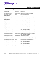
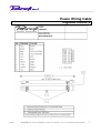
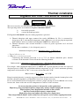
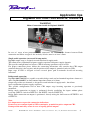
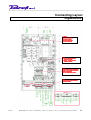
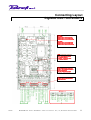
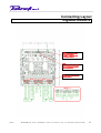
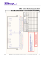
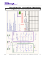
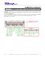
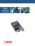
6/24/02
DigiMod 500
DigiMod 1000
DigiMod 1500
DigiMod 2000HV
DigiMod 1000NPS
User Manual
COD: MAN-DGM-USER_MAN19-EN-11
NOV 2007
Caution
DigiMod 500/1000/1500/2000HV/1000NPS
CAUTION
RISK OF ELECTRIC SHOCK
DO NOT OPEN
!
IMPORTANT SAFETY INSTRUCTIONS!
! Read these instructions !
! Keep these instructions !
! Heed all warnings !
! Follow all instructions !
CAUTION: To reduce the risk of electric shock, do not remove the cover. No userserviceable parts inside. Refer servicing to qualified service personnel.
WARNING: To prevent fire or electric shock, do not expose this equipment to rain or
moisture.
SAFEGUARDS: Electrical energy can perform many useful functions. This unit has been
engineered and manufactured to assure your personal safety. Improper use can result in
potential electrical shock or fire hazards. In order not to defeat the safeguards, observe the
following instructions for its installation, use and servicing.
NOTES: This equipment has been tested and found to comply by Competent Body (Directive
89/336/EEC-EMC) pursuant to the product family standard for audio professional use:
EN 55103-1 and EN 55103-2 standard (with the limits for E1 and E2 electromagnetic
environment); EN61000– 3 – 2 , EN 61000 – 3 - 3
This is a Class A product (ClassB from s/n 18000). In a domestic environment this product may
cause radio interferences in which case the user may be required to take adequate measures.
This equipment has been tested and found to comply by Notified Body 0715 (Directive 73/23/EEC
L.V) pursuant to the audio apparatus safety requirements: Standard EN 60065.
Warning Notices
Location
Install the amplifier in a ventilated enclosure (IP20 at least), where it will not be directly exposed to high
temperature or humidity.
Do not install the amplifier in a location that is exposed to direct rays of the sun, or near to hot appliances or
radiators. Excessive heat can adversely affect the operation and internal components. Installation of the
module in a damp or dusty environment may result in malfunction or accident.
Precautions regarding installation
Placing and using the amplifier for long periods on heat-generation sources will affect performances. Avoid
placing the amplifier on heat-generating sources. Install this amplifier as far as possible from tuners and TV
sets. An amplifier installed in close proximity to such equipment may cause noise or degradation of the
picture.
07/11/07
Powersoft s.r.l. - P. IVA n. 04644200489 – Via E.Conti, 5 Scandicci - Tel.: (+39) 055 7350230- Fax: 055 7356235
2
Safety rules
DigiMod 500/1000/1500/2000HV/1000NPS
CAUTION
RISK OF ELECTRIC SHOCK
DO NOT OPEN
!
This device must be powered exclusively by earth connected mains sockets in electrical networks
compliant to the IEC 364 or similar rules.
Is absolutely necessary to verify this fundamental requirement of safety and, in case of doubt,
require an accurate check by a qualified personal.
Is absolutely necessary to ground this device using the proper earth connection on the metal frame
of the chassis, use M4 nut and proper Grover type washer to secure the earth terminal lug.
The constructor cannot be considered responsible for eventual damages caused to persons, things
or data for the missing of accurate earth link.
Provide the installed unit with bipolar switch to unconnect both mains connection with at least 3mm
of distance of the switch contacts.
Before powering this device verify that the module is supplied with the correct voltage rating.
Verify that your mains connection is capable to satisfy the power ratings of the device.
Do not spill water or other liquids into or on the unit.
Do not use this unit if the electrical power cord is frayed or broken.
Do not remove the cover. Removing the cover will expose you to potentially dangerous voltage.
No naked flame sources such like lighted candles should be placed on the module.
Contact the authorized center for ordinary and extraordinary maintenance.
Input mains and output power connection wirings must not to be accessible to the user.
The enclusure apparatus shall be designed so that the start and spread of fire is prevented as
much as possible , and shall not give rise to danger of fire to the surrounding of the apparatus.
This is achieved as follows:
- by using good engineering practice in design and production of the enclosure apparatus to
avoid potential ignition sources
- by using materials of low flammability for internal parts in the vicinity of potential ignition
sources
- by using fire enclosures to limit the spread of fire
07/11/07
Powersoft s.r.l. - P. IVA n. 04644200489 – Via E.Conti, 5 Scandicci - Tel.: (+39) 055 7350230- Fax: 055 7356235
3
Specifications
DigiMod 500/1000/1500/2000HV/1000NPS
SPECIFICATIONS
GENERAL
Type .......................................................................................... high efficiency 1/2 channels amplifier for professional applications
POWER REQUIREMENTS
DigiMod1000 / (DigiMod500)
230Vrms mains voltage selection ............................................... AC 230+/ - 10 % 50/60 Hz / 1.6 (1.0) A
115Vrms mains voltage selection ............................................... AC 115+/ - 10 % 50/60 Hz / 2.6 (2.0) A
DigiMod1500
230Vrms mains voltage selection ............................................... AC 230+/ - 10 % 50/60 Hz / 2.2 A
115Vrms mains voltage selection ............................................... AC 115+/ - 10 % 50/60 Hz / 3.6 A
DigiMod2000HV
230Vrms mains voltage selection ............................................... AC 230+/ - 10 % 50/60 Hz / 2.9 A
115Vrms mains voltage selection ............................................... AC 115+/ - 10 % 50/60 Hz / 5.5 A
DigiMod500+DigiMod1000NPS/ DigiMod1000+DigiMod1000NPS
230Vrms mains voltage selection ............................................... AC 230+/ - 10 % 50/60 Hz / 2.2 A
115Vrms mains voltage selection ............................................... AC 115+/ - 10 % 50/60 Hz / 3.6 A
POWER REQUIREMENTS DigiMod1000NPS
Power bus .................................................................................. Dc +/- 75 V (+8% -20%)@(7 A)
Auxiliary supply........................................................................... Dc +15V (+30% -15%)@(0.7 A) / -15 V (+30% -15%)@ (0.3 A)
+7V (+30% -15%)@(0.5 A)
All requirements are provided by a master DigiMod 500 orDigiMod 1000 thru slave connector
DIMENSIONS / WEIGHTS
Weight ........................................................................................ 1.0 Kg DigiMod500
Weight ........................................................................................ 1.1 Kg DigiMod1000
Weight ........................................................................................ 1.15 Kg DigiMod1500/2000HV
Weight ........................................................................................ 0.6 Kg DigiMod1000NPS
External dimensions ................................................................... 216mm (W), 122mm (D), 51mm (H) DigiMod500/1000/1500
External dimensions ................................................................... 146mm (W), 122mm (D), 51mm (H) DigiMod1000NPS
AUDIO SECTION
Slew Rate (8Ω) ....................................... 50V/Us
Gain (Digimod500/1000/1500/1000NPS) ....... 32 dB
S/N ratio ................................................. 105 dB/A
Gain (Digimod2000HV) .................................. 38 dB
Distortion ................................................ <0.5% (THD, DIM, SMPTE)
Output ............................................................ Unbalanced to ground
Inputs...................................................... Balanced to ground
Bandwidth ...................................................... 10 Hz - 30KHz
Impedance.............................................. 10 KΩ
Damping factor 500Hz/8Ω (Digimod500/1000/1500/1000NPS) ................ > 500
Damping factor 500Hz/8Ω (Digimod2000HV) ........................................... > 100
POWER SPECIFICATIONS
DigiMod500
(measured at 115 or 230V AC, 50/60Hz)
DigiMod500+DigiMod1000NPS
Power continuous
(1KHz, 0.5% THD) 4Ω = 450W 8Ω = 260W
Power EIAJ
(1KHz, 1% THD) 4Ω = 530W 8Ω = 280W
Power continuous, all channels driven
(1KHz, 0.5% THD) 4Ω = 3X 350W 8Ω = 3X 230W
Power EIAJ, all channels driven
(1KHz, 1% THD) 4Ω = 3X 410W 8Ω = 3X 250W
Power continuous, both channels driven
(1KHz, 0.5% THD) 4Ω = 2X 390W 8Ω = 2X 240W
Power EIAJ, both channels driven
(1KHz, 1% THD) 4Ω = 2X 500W 8Ω = 2X 270W
Bridged 8Ω = 1000W 16Ω = 520 W
Power continuous, all channel driven
(1KHz, 0.5% THD) 4Ω = 4X 310W 8Ω = 4X 210W
Power EIAJ, all channels driven
(1KHz, 1% THD) 4Ω = 4X 375W 8Ω = 4X 230W
Bridged 8Ω = 2X 750W 16Ω = 2X 460W
Power continuous, both channels driven
(1KHz, 0.5% THD) 4Ω = 2X 590W 8Ω = 2X 330W
Power EIAJ, both channels driven
(1KHz, 1% THD) 4Ω = 2X 750W 8Ω = 2X 370W
Bridged 8Ω = 1500W 16Ω = 740W
Power continuous, both channels driven
(1KHz, 0.5% THD) 8Ω = 2X 780W 16Ω = 2X 440W
Power EIAJ, both channels driven
(1KHz, 1% THD) 8Ω = 2X 1050W 16Ω = 2X 570W
Bridged 16Ω = 2100W 32Ω = 1140W
DigiMod1000
DigiMod1500
DigiMod1000+DigiMod1000NPS
DigiMod2000HV
FUNCTIONS
• Thermal protection (over-temperature power limiting, thermal shutdown)
• Short-circuit / overload output protection
• Clip limiter, Permanent signal limiter, High frequency protection
• Auxiliary output voltage (±12V regulated , 200mA )
• Bypass outputs for external active/passive filters
• Digimod500/1000/1000NPS: Temperature controlled Fan output (CN10)
• Digimod1500/2000HV: Temperature controlled Fan
• DSP based or Analog processing plugin optional boards
07/11/07
Powersoft s.r.l. - P. IVA n. 04644200489 – Via E.Conti, 5 Scandicci - Tel.: (+39) 055 7350230- Fax: 055 7356235
4
Connection description
DigiMod 500/1000/1500/2000HV/1000NPS
CN3:
PIN1, POWER OUTPUT CHANNEL 1 POSITIVE
PIN2, POWER OUTPUT CHANNEL 1 NEGATIVE
CN11:
PIN1,
PIN2,
PIN3,
PIN4,
CN14:
PIN1, AUXILIARY SUPPLY OUTPUT GROUND
PIN2, MUTE CONTROL PIN, PULL DOWN TO GROUND TO MUTE BOTH
OUTPUTS
PIN3, +12VOLTS DC REGULATED AUXILIARY OUTPUT,
CURRENT SHALL NOT EXCEED 200 mA.
PIN4, -12VOLTS DC REGULATED AUXILIARY OUTPUT,
CURRENT SHALL NOT EXCEED -200 mA.
CN12:
PIN1,
PIN2,
PIN3,
PIN4,
CN7:
PIN1, POWER OUTPUT CHANNEL 2 POSITIVE ( ground connected)
PIN2, POWER OUTPUT CHANNEL 2 NEGATIVE (hot pole, CHANNEL 2 has reversed
.
polarity to have bridged output with CHANNEL 1 directly between positive output of
.
CH1 with negative output of CH2; input stage of CH1 is phase reversing ).
CN1:
PIN1, PIN2, MAINS INPUT FOR BOTH 115V AND 230 OPERATION,
SEE CN2 FOR VOLTAGE SELECTION.
CN2:
PIN1,PINS2 OPEN FOR 230VAC OPERATION, CONNECT PIN1 TO PIN2 FOR 115VAC
OPERATION. DEFAULT SELECTION 230VAC.
(SEE PAG 10/13 DRAWING FOR LOCATION)
CN10:
PIN1,PIN3 TO NEGATIVE WIRE OF EXTERNAL 24VDC FAN
PIN2 TO POSITIVE WIRE OF EXTERNAL 24VDC FAN
CN8:
PIN1 TO 72 SEE PAGE 13
SIGNAL GROUND CHANNEL 1
BALANCED INPUT + CHANNEL 1
BALANCED INPUT – CHANNEL 1
OUTPUT TO EXTERNAL VOLUME CONTROL CHANNEL 1,
R Potentiometer = 1KOhm to 2.7Kohm, linear type
(remove J1 placed on pins 3,4 of CN17 to insert external potentiometer)
PIN5, INPUT FROM EXTERNAL VOLUME CONTROL CHANNEL 1,
SIGNAL GROUND CHANNEL 2
BALANCED INPUT + CHANNEL 2
BALANCED INPUT – CHANNEL 2
OUTPUT TO EXTERNAL VOLUME CONTROL CHANNEL 2,
R Potentiometer = 1KOhm to 2.7Kohm, linear type
(remove J2 placed on pins 1,2 of CN18 to insert external potentiometer)
PIN5, INPUT FROM EXTERNAL VOLUME CONTROL CHANNEL 2,
!WARNING!
CHECK PROPER VOLTAGE SELECTION BEFORE OPERATE
CHECK PROPER CHASSIS EARTH CONNECTION BEFORE OPERATE
07/11/07
Powersoft s.r.l. - P. IVA n. 04644200489 – Via E.Conti, 5 Scandicci - Tel.: (+39) 055 7350230- Fax: 055 7356235
5
Mating connectors
DigiMod 500/1000/1500/2000HV/1000NPS
Connectors ID
Manufacturer
Model/Code
CN1 (2POLES 7.5mm)
(DigiMod500/1000/1500)
CN1 (2 poles, Faston)
(DigiMod2000HV)
Phoenix Contact
GMSTB 2,5/2-ST(Cod. Ph.C. 1766880)
(Cod. Powersoft CN000153)
6.3x0.8 mm female Faston
CN2 (2POLES 7.5mm)
(DigiMod500/1000/1500)
CN2 (2 poles, Faston)
(DigiMod2000HV)
CN3 (2POLES 5.08mm)
(DigiMod500/1000/1500)
CN3 (2 poles, Faston)
(DigiMod2000HV)
CN7 (2POLES 5.08mm)
(DigiMod500/1000/1500)
CN7 (2 poles, Faston)
(DigiMod2000HV)
Various
Phoenix Contact
Various
Phoenix Contact
Various
Phoenix Contact
Various
GMSTB 2,5/2-ST (Cod. Ph.C. 1766880)
(Cod. Powersoft CN000153)
6.3x0.8 mm female Faston
MSTB 2,5/2-ST-5,08 (Cod. Ph.C. 1757019)
(Cod. Powersoft CN000149)
4.8x0.8 mm female Faston
MSTB 2,5/2-ST-5,08 (Cod. Ph.C. 1757019)
(Cod. Powersoft CN000149)
4.8x0.8 mm female Faston
CN14 (4POLES 5.08mm)
Phoenix Contact
MSTB 2,5/4-ST-5,08 (Cod. Ph.C. 1757035)
(Cod. Powersoft CN000151)
CN11 (5POLES 5.08mm)
Phoenix Contact
MSTB 2,5/5-ST-5,08 (Cod. Ph.C. 1757048)
(Cod. Powersoft CN000152)
CN12 (5POLES 5.08mm)
Phoenix Contact
MSTB 2,5/5-ST-5,08 (Cod. Ph.C. 1757048)
(Cod. Powersoft CN000152)
CN10 (3POLES 2.54mm)
Molex22-01-2035 (Molex ordering number )
CN15 (10POLES 3.0mm)
Molex
43025-1000 (Molex Housing ordering number)
43030-0001 (Molex contact ordering number )
CN8 (72POLES Simm socket) Various
Right polarized / 1,27mm Pcb thickness
CN16 (8 POLES 2.54mm)
Berg
DUBOX (Cod. Ph.C. 76384-308)
(Cod. Powersoft CN000218)
CN17 (4 POLES 2.54mm)
Berg
DUBOX (Cod. Ph.C. 76384-304)
(Cod. Powersoft CN000217)
CN18 (4 POLES 2.54mm)
Berg
DUBOX (Cod. Ph.C. 76384-304)
(Cod. Powersoft CN000217)
07/11/07
Powersoft s.r.l. - P. IVA n. 04644200489 – Via E.Conti, 5 Scandicci - Tel.: (+39) 055 7350230- Fax: 055 7356235
6
Power Wiring Cable
DigiMod1000NPS
07/11/07
Powersoft s.r.l. - P. IVA n. 04644200489 – Via E.Conti, 5 Scandicci - Tel.: (+39) 055 7350230- Fax: 055 7356235
7
Thermal constrains
DigiMod 500/1000/1500/2000HV/1000NPS
CAUTION
RISK OF ELECTRIC SHOCK
DO NOT OPEN
!
This device must be correctly heatsinked for correct and reliable operation:
Two operating modes are feasible for DigiMod 500/1000/1000NPS.
1)
2)
fan cooled operation
external heatsink operation
For Digimod1500/2000HV only fan cooling operation is provided
1) Thermal behaviour with upper mounted fan cooler (80X80mm, 24 Vdc) is warranted by
design up to 50°C enviromental temperature with 6 dB power crest factor program operation,
both channels driven on 4 ohms load (Digimod 2000HV on 8 ohms load)
2) Thermal behaviour with external heatsink is related to power operation level and load
impedance.
For the above conditions (1), the dissipated power is:
Maximum dissipated power = Maximum power · (1-Efficiency*)
4**
* Typical efficiency = 0.8
** 6 dB power crest factor program
Considering that thermal protection is set at 75°C on bottom aluminium plate, thermal
resistance of the heatsink is derived from the following formula:
Rth(heatsink) = Maximum operating temperature – Maximum ambient temperature
Maximum dissipated power
For example, with a maximum output power of 1000W and a typical efficiency of 80% the expected
dissipated power is 50W. For a maximum ambient temperature of 45°C and a maximum operating
temperature of the module of 70°C is necessary an heatsink of 0.5°C/W
Rth(heatsink) = 70°C – 45°C = 0.5°C/W
50W
Proper heatsink planarity is strongly suggested to allow thermal transfer from the bottom plate to the
heatsink, thermal compound is recommended also if not strongly necessary.
In case of installation inside of loudspeaker enclosure, proper spacing of at least 100 mm is necessary
between the frame of the unit and side components or surfaces of the enclosure.
Be Aware that this product is designed for audio applications.
High energy long term high frequency output may damage output damping RC network.
High frequency time shaped built in limiter works to limit
high level steady high frequency output signals.
High energy long term output may blow power supply fuses.
Time shaped built in limiter works to limit eccessive power and to reduce clipping distortion.
07/11/07
Powersoft s.r.l. - P. IVA n. 04644200489 – Via E.Conti, 5 Scandicci - Tel.: (+39) 055 7350230- Fax: 055 7356235
8
Application tips
DigiMod 500/1000/1500/2000HV/1000NPS
WARNING!
Mains Connections details for Digimod 2000HV
In case of usage of not protected fast-on connectors, the minimum air distance between Earth
connection and mains energized fast-on body / blades, must be at least 2,5mm.
Single ended operation (stereo and bi-amp mode):
DigiMod output stage is designed to work in balanced supply mode.
This allows better exploitation of power supply capacitors and power supply dynamic.
This specific configuration lead to have CH2 in inverting operation respect to CH1.
For proper connection please follow the connecting instructions and consider that CH2 output
connector hot pole is the negative and the positive of the output is grounded (only for CH2).
Input stage of CH2 is designed to have reversed phase path to maintain overall not inverting
behaviour.
Bridge mode operation:
DigiMod1000/1500/NPS are capable to work in bridge mode on load nominal impedance down to 8
ohms, DigiMod2000HV on load nominal impedance down to 16 ohms
Output stage of the two channels is designed to work in balanced supply mode , that allows
better exploitation of power supply capacitors.
This specific configuration lead to have CH2 output stage inverting operation as previously
mentioned.
Bridge mode connection on inputs is performed directly paralleling the inputs without phase
reversing (INPUT+1 wired to INPUT+2 and INPUT-1 wired to INPUT-2).
Bridge mode connection on outputs is performed directly wiring the load between OUTPUT+1 and
OUTPUT-2.
Note:
It is important to respect the connection indications.
Do not to reverse output signal of CH2 to maintain grounded negative output on CH2.
Damage of the unit may occurr in case of equally phased outputs.
07/11/07
Powersoft s.r.l. - P. IVA n. 04644200489 – Via E.Conti, 5 Scandicci - Tel.: (+39) 055 7350230- Fax: 055 7356235
9
Connecting Layout
DigiMod500
!
" #
$%
!
#
"
!
07/11/07
Powersoft s.r.l. - P. IVA n. 04644200489 – Via E.Conti, 5 Scandicci - Tel.: (+39) 055 7350230- Fax: 055 7356235
10
Connecting Layout
DigiMod1000/1500/2000HV
For Digimod1000
F1
! = 5X20, 4A slow blow for 230Vrms
Mains operation
" #
F1 = 5X20, 6,3A
$%
!slow
#blow for 115Vrms
Mains opearation
$%
! #
For Digimod1500
F1 = 5X20, 6,3A
$%
!slow
#blow for 230Vrms
Mains operation #
# for 115Vrms
F1 = 5X20, 10A slow blow
Mains opearation
CN10 = 24Vdc Fan Connector
Pin
" out:
1 - negative fan wire
2 - positive fan wire
3!- negative fan wire
CN15 = Power connector for
slave unit wiring
CN8 = Simm board connector
see details
07/11/07
Powersoft s.r.l. - P. IVA n. 04644200489 – Via E.Conti, 5 Scandicci - Tel.: (+39) 055 7350230- Fax: 055 7356235
11
Connecting Layout
DigiMod1000NPS
"
!
07/11/07
Powersoft s.r.l. - P. IVA n. 04644200489 – Via E.Conti, 5 Scandicci - Tel.: (+39) 055 7350230- Fax: 055 7356235
12
CN8 Simm Socket application
DigiMod 500/1000/1500/2000HV/1000NPS
07/11/07
Powersoft s.r.l. - P. IVA n. 04644200489 – Via E.Conti, 5 Scandicci - Tel.: (+39) 055 7350230- Fax: 055 7356235
13
CN11,CN12,CN16 interface board application
DigiMod 500/1000/1500/2000HV/1000NPS
07/11/07
Powersoft s.r.l. - P. IVA n. 04644200489 – Via E.Conti, 5 Scandicci - Tel.: (+39) 055 7350230- Fax: 055 7356235
14
DGMDSPA installation
DigiMod 500/1000/1500/2000HV/1000NPS
DGMDSPA installation consist in removing J3 and J4 jumpers to allow signal path to flow to
DGMDSPA board or remove the jumpers located on pins 3,4 of CN18 and 1,2 of CN17 ( in the
latest releases of the units) .
Insert the DGMDSPA board on the only one spare simm socket on the main board of DigiMod
module. Take care that side holders are correctly closed and the polarization is respected.
The module is ready to work.
07/11/07
Powersoft s.r.l. - P. IVA n. 04644200489 – Via E.Conti, 5 Scandicci - Tel.: (+39) 055 7350230- Fax: 055 7356235
15