1
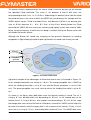
VARIO User manual
Document version 2.0
2012 FLYMASTER Avionics Ltd.
R. de Fundões,nº 151
3700-121 S. João da Madeira
Portugal
Tel: + 351 256 001 935
Fax: + 351 256 880 551
All rights reserved. Except as expressly provided herein, no part of this manual may be
reproduced, copied, transmitted, disseminated, downloaded or stored in any storage
medium, for any purpose without the express prior written consent of FLYMASTER
Avionics Lda. herein FLYMASTER avionics. FLYMASTER Avionics hereby grants
permission to download a copy of this manual onto a hard drive or other electronic storage
medium to be viewed and to print a copy of this manual or of any revision hereto, provided
that such electronic or printed copy of this manual must contain the complete text of this
copyright notice and provided further that any unauthorized commercial distribution of this
manual or any revision hereto is strictly prohibited.
Information in this document is subject to change without notice. FLYMASTER Avionics
reserves the right to change or improve its products and to make changes in the content
without obligation to notify any person or organization of such changes or improvements.
Visit the FLYMASTER Avionics website (www.flymaster-avionics.com) for current updates
and supplemental information concerning the use and operation of this and other
FLYMASTER Avionics products.
Document version: 2.0
Page 2
Warning
It is the sole responsibility of the pilot to operate the aircraft in a safe manner, maintain full
surveillance of all flying conditions at all times, and not become distracted by the Flymaster
VARIO. Flymaster Avionics is not responsible for any damages resulting from incorrect or
no data provided by the Flymaster VARIO. Flight safety is the sole responsibility of the
pilot.
It is unsafe to operate the Flymaster VARIO while in the air. Failure by the pilot equipped
with a Flymaster VARIO to pay full attention to the aircraft and flying conditions while flying
could result in accident with property damage and/or personal injury.
Document version: 2.0
Page 3
Table of Contents
1 Introduction......................................................................................................................................5
2 Overview..........................................................................................................................................5
3 Getting started..................................................................................................................................6
3.1 Charging the Battery.................................................................................................................6
3.2 VARIO Keys.............................................................................................................................7
3.3 Using keys Inside Menu...........................................................................................................7
3.4 Switching VARIO On and Off..................................................................................................8
3.5 Resetting the VARIO................................................................................................................8
4 Flight Mode......................................................................................................................................9
5 VARIO Elements............................................................................................................................10
5.1 Graphical Elements.................................................................................................................10
5.1.1 Battery.............................................................................................................................10
5.1.2 Sound...............................................................................................................................11
5.1.3 Analog Vario....................................................................................................................12
5.1.4 Big Analog Vario.............................................................................................................12
5.1.5 Altitude graph..................................................................................................................13
5.2 Data field Elements.................................................................................................................14
6 Menu mode.....................................................................................................................................15
6.1 Flight Log...............................................................................................................................16
6.2 Set Altimeter...........................................................................................................................17
6.3 Time........................................................................................................................................17
6.4 Vario Acoustics.......................................................................................................................18
6.4.1 Sinking/Climbing Threshold...........................................................................................18
6.4.2 Sink Alarm......................................................................................................................18
6.4.3 Base Frequency...............................................................................................................18
6.4.4 Increments.......................................................................................................................19
6.4.5 Volume............................................................................................................................19
6.5 Advanced Features..................................................................................................................20
6.5.1 Damper............................................................................................................................20
6.5.2 Cadence...........................................................................................................................20
6.5.3 Dynamic Frequency........................................................................................................21
6.5.4 Buzzer.............................................................................................................................21
6.5.5 Auto Silent.......................................................................................................................22
6.5.6 Integration.......................................................................................................................23
6.6 Screen......................................................................................................................................23
6.7 Language/Units.......................................................................................................................23
6.8 Device Settings.......................................................................................................................24
6.9 RF Probes................................................................................................................................25
7 Firmware.........................................................................................................................................25
Document version: 2.0
Page 4
1 Introduction
Thank you for choosing FLYMASTER VARIO. If you have any questions or comments
regarding the use of our equipment you can visit our website or contact our Support
Department ([email protected]).
This manual covers Firmware versions up to 1.01v If you have a more recent version of
firmware some of the features may not be covered.
2 Overview
Figure 1 - VARIO Overview
Document version: 2.0
Page 5
3 Getting started
Fully charge battery before using FLYMASTER VARIO for the first time.
Figure. 2 - USB Connector
The battery may be charged by either connecting the VARIO USB connector to the wall
socket charger or USB cable. USB connector can be found on the right side of the VARIO
(see Figure. 2).
3.1 Charging the Battery
Flymaster VARIO has a completely new battery power management, that gives the pilot a
more accurate information about the battery state, as well as the charging time and battery
remaining time.
To charge the Flymaster VARIO battery you can use the wall charger, the Usb cable, or the
car charger. Flymaster accessories are recommended in order to avoid damage the power
management module.
Charging, or battery status information is shown in the Shutdown menu.
When not being charged, the remaining battery level is shown as a percentage. In addition
the estimated remaining working time (TTG) is shown. Both values are estimated based
on the average consumption of the device since the last charge. Naturally, any change in
consumption profile results in an estimation error.
The Flymaster VARIO has 2 charging modes, namely, “Quick Charge” and “Slow charge”.
The charging mode choice is made automatic.
Quick charge mode is only choose when the wall charger, or the car charger are used,
while Slow Charge mode is choose when is used a USB cable connected to a Pc.
Note: Charging is not possible when the device is turned on, and the device is
connected to a PC. In order to start charging the device should be turned off.
Document version: 2.0
Page 6
Information about the charging process can be seen in the shutdown page, or in the center
of the display when the device is turned off. In both cases information displayed includes:
the charging mode, slow or quick; the current battery level in percentage; and the
remaining charging time in hh:mm format.
Note: Charging should be avoided at high temperatures in order to reduce the
probability of battery overheating.
3.2 VARIO Keys
Four keys are used to interact with VARIO (see Figure. 3). In this manual we will call
MENU key to S1, ENTER key to S2, UP key to S3, and DOWN key to S4. Each key has 2
functions depending on whether the device is in flight mode or in menu mode. Additionally
the MENU key is used to “power-up” the VARIO when it is switched off.
Figure. 3: Keys
In Flight Mode each key has a specific functions, which is indicated by a symbol draw in
the key. The symbol are self explanatory, so key S4 allows resetting Altimeter 3, S1
change to menu Mode, S2 switch the layout page, and S3 to change the volume. The
volume can also be changed trough the Menu (see section 6.4.5 )
3.3 Using keys Inside Menu
Changing parameters on the VARIO can be performed through the menu. Changing a
parameter involves accessing the menu, selecting an option, and then changing a specific
field value.
Accessing the main menu can be done by pressing the MENU key in flight mode. Once in
Document version: 2.0
Page 7
the menu, UP, and DOWN keys can be used to scroll up, and down, through the menu
options list. Once the desired option is selected, the option is highlighted, and the ENTER
key should be used to access the option. Depending on the menu option, either appears a
new menu options list, or a data fields list appears. Going back from a menu can be
achieved using the MENU key.
When accessing data fields the associated menu option becomes “grayed” and the
respective field data item is highlighted. Using the UP, and DOWN, keys changes the
value on each field. When the correct value appears pushing the ENTER key moves to the
next field, or in same cases to the next character/digit. Conversely, pushing MENU key
moves to the previous field, or to the next character/digit.
If the ENTER key is pushed on the last field all the data in the selection section is stored
and control returns to the configuration menu. Inversely, if the MENU key is pushed on the
first data field the changed settings are ignored and control is returned to the configuration
menu.
When setting a data field that involves setting several characters, e.g. when defining a
waypoint name, after defining the desired characters, then pushing the ENTER key
continually for more than 2 seconds will make the cursor jump to the next data field, or
return to the configuration menu if no more data field needs to be set.
3.4 Switching VARIO On and Off
To switch on the VARIO, briefly push the S1 key (Menu Key). This will display the start
up screen with a 10 second countdown . Pushing the S2 (Enter key) before the 10
seconds have elapsed will power up the VARIO. VARIO initiates in flight mode. If the S2
key is not pushed within 10 seconds the VARIO will go back to sleep.
To switch off the VARIO, push the S1(menu key) to activate menu mode, using the
arrow keys (S3 or S4) scroll the cursor to the “Shutdown” item and push the S2(Enter
Key).
3.5 Resetting the VARIO
The reset procedure allows the pilot to restart the VARIO if it freezes, or stop
responding. To reset the VARIO just push S1 (Menu key) and the S4 (Down arrow key)
Document version: 2.0
Page 8
keys simultaneously for at least two seconds.
4 Flight Mode
The Flymaster VARIO has two main working modes, namely Flight mode, and Menu
mode. Flight moe is used during flight, and this allows the user to see information such as
Altitude, or Vario. The VARIO has up to 16 different pages (see Figure. 4) in memory. Each
page corresponds to a different screen, which can be completely configured by the user. A
set of 16 pages is called a Layout. Once a Layout containing multiple pages has been
defined, the user can switch page using the S2 Key(ENTER) in Flight Mode.
Figure. 4 - Layout pages examples
Screen layout can be configured by the user using a free application, called “Flymaster
Designer” which can be downloaded from the Flymaster website (www.flymaster.net). This
intuitive tool allows the user to create an unlimited number of layouts, which can be saved
to the computer, uploaded to the instrument, and even shared with other Flymaster users.
Document version: 2.0
Page 9
See the Designer user manual, available on the website for more information about the
Designer tool.
Designing a Layout consists of inserting a set of objects, called Elements, in the desired
position, and with the desired dimensions, in each of the available 16 pages. The Designer
works by “what you see is what you get”. This means that when you insert a element in a
page, and after uploading the layout to the instrument, you will see exactly the same thing
on the VARIO screen.
There are several elements available for the VARIO which are presented in the following
section.
5 VARIO Elements
The main objective of an element is to provide information to the user. Elements can be
Graphical, or Data Field type. Each element have its own properties which can be
changed in order to alter the element behavior, and/or shape.
5.1 Graphical Elements
Graphical elements are characterized by providing information in a graphical way. Most of
the graphical elements have fixed dimensions, although their position can be altered.
As the VARIO firmware evolves the list of Graphical Elements will likely grow. The current
version includes the following graphical elements.
5.1.1 Battery
The Battery Element provides a graphical indication of the current battery level. In Table 1
it is possible to see the relationship between what is shown and the actual battery level in
percentage. This element has fixed dimensions.
Document version: 2.0
Page 10
Table 1 - Battery Element description
Symbol
Description
•Battery level above 90%
•Battery level between 70% and 89%
•Battery level between 50% and 69%
•Battery level between 30% and 49%
•Battery level between 15% and 29%
•Less than 15% battery remaining
5.1.2 Sound
The Sound Element provides graphical representation on the current volume level. Table 2
Shows the relationship between what is shown and the sound level. This element has
fixed dimensions.
Table 2 - Sound Element description
Symbol
Description
•Sound Level 6 (maximum sound level)
•Sound Level 5
•Sound Level 4
•Sound Level 3
•Sound Level 2
•Sound Level 1
•Sound is muted (No sound)
Document version: 2.0
Page 11
5.1.3 Analog Vario
The Analog Vario Element shows information regarding the analogue instantaneous
vertical speed. This element can be resided and re-positioned.
This Element graphically represents the rate of climb, scaled from 0 m/s to +/-10 m/s
depending if you are climbing or sinking.
Figure. 5 - Analog Vario Element
When the VARIO detects that the pilot is climbing, a black bar starts to grow on the left,
from the bottom of the scale to the top ,with 0,1 m/s increments. The same bar grows on
the right, from the top of the scale to the bottom, if sinking is detected.
5.1.4 Big Analog Vario
The big analog Vario element shows the instantaneous vertical speed like the one in the
previews section. This element can be resized and re-positioned.
Figure. 6 - Analog Big Vario Element
This Element graphically represents the rate of climb, scaled from 0 m/s to +/-10 m/s
depending if you are climbing or sinking.
Document version: 2.0
Page 12
In this Element a black bar starts from the middle of the scale and grows at 0,1 m/s
increments, up to 5 m/s at the top of the scale. When 5 m/s value is reached the black bar
starts to disappear from 0 m/s (middle of the scale) until the top of the scale. When the bar
completely disappears the climbing rate is equal, or above 10 m/s.
The same process occurs when descending, but from the middle of the scale to the
bottom.
5.1.5 Altitude graph
The Altitude graph element (see Figure. 7) corresponds to a graph altitude versus time.
Altitude is shown in the vertical axis graduated in meters with time shown on the horizontal
axis graduated in seconds.
Figure. 7 Altitude graph element
The range of the horizontal axis is fixed and corresponds to 240 seconds (4 minutes),
while the range of the vertical axis is automatically adjusted in order to accommodate the
gained height. In reality the altitude graph element is a plot of the absolute altitude over the
last 4 minutes of flight (see Figure. 8).
Figure. 8 Altitude plot
Document version: 2.0
Page 13
5.2 Data field Elements
Data field elements can be used to shown numerical information like altitude, time,
amongst others. These elements have configurable size, and position, although the text
within has only 3 possible sizes. Table 3 explains the available data fields. As the VARIO
firmware evolves this list will likely grow.
Table 3 - Data fields Description
Field ID
Description
Abs.
Pressure
Absolute atmospheric pressure value in Pascals.
Above Toff
Altitude above takeoff is the altitude over the flight starting point.
Alt. Gain
Altitude Gain. Altitude gained in current thermal (see Note 1).
Altitude
Current altitude. This altitude is calculated based on the barometric pressure, and
depends on the QNH value (see Note 2).
Altitude2
Second Altimeter which can be set independently to the main altimeter.
Ave.Vario
Average Vario calculated using an integration time constant in order to indicate
smoother climbing rates.
Date
Current date.
Dur.
Flight Duration. Duration of the current flight.
Flight Level Current altitude in hundreds of feet.
Fuel Level
Fuel level in liters (available when connected with Flymaster M1).
Max.Alti
Maximum altitude reached during current flight. This is based on barometric
altitude.
Max.Climb
Once a flight has started, it shows the maximum rate of climb encountered during
the flight. This value uses the integrated vario not the instantaneous rate of climb.
This provides good indication of the quality of the day's thermals. This value is
reset when the instrument is switched off.
Max.Sink
Once a flight has started shows the maximum sink encountered during the flight.
Note that these values are using the integrated vario. When the instrument is
switched off this value is reset back to zero.
Motor
Temp.
Motor Temperature (available when connected with Flymaster M1).
Page
Current layout active page number.
Document version: 2.0
Page 14
Number
RPM
Motor rotation (available when connected with Flymaster M1).
Time
Current Time.
Vario
Numeric value of the instantaneous Vario (shown in vario graph).
Voltage
Current battery level in Volts
Note 1- The VARIO considers a thermal has been entered when the integrated vario value
is above 0.5m/s and considers the thermal as been exited when the integrated vario goes
bellow -1.0 m/s. Once in the thermal the Gain indicator will keep track of the maximum
altitude reached in the thermal. If the altitude is less than the the max thermal altitude then a
negative number will show the difference from the highest point reached. If the altitude is
equal or higher than the maximum reached then a positive number will show the altitude
gained since entering the thermal. The Gain indicator keeps track of how much altitude is
being gained in the thermal. When a pilot enters a thermal the VARIO will reset the Gain
indicator to 0 and will start to track how much altitude the pilot has gained. At a certain point
in the thermal the lift may become weaker and inconsistent. At this point the gain indicator
will show altitude loss in this inconsistency. Once the pilot climbs in the thermal again the
indicator will show the gain since entering the thermal.
Note 2- The “altitude” field (see Figure 6) indicates the absolute height in meters or feet
depending on the setting. This altitude corresponds to the barometric altitude and thus
depends totally on the QNH (absolute pressure at a given moment and location in regards
to the correspondent pressure at MSL).
The altimeter cannot be reset, but can be set using the corresponding menu option (see
section 6.2 ).
6 Menu mode
When in flight mode, pushing the menu (S1) button accesses the menu mode. When in
menu mode pushing the menu(S1) button will go back to flight mode.
Document version: 2.0
Page 15
Figure. 9 - Main Menu Screen
To access the different items on the menu you can use the UP(S3) and DOWN(S4) keys.
Once a menu item is selected pushing the ENTER (S2) executes the selected function.
The main menu screen can be seen in Figure. 9.
6.1 Flight Log
The Flight Log option allows the user to access information about previous saved flights. In
the top of the screen a list of flights is showed. Each flight is identified by the take off
date ,time and flight duration.
Flights can be selected using UP and DOWN keys. For each flight the flowing information
is displayed:
•Max. Altitude – Maximum altitude during flight (ASL).
•T.off Alti. - Take off altitude.
•Min. Sink – Maximal sinking rate
•Max Climb – Maximal climbing rate
Document version: 2.0
Page 16
Figure. 10 - Flight Log
6.2 Set Altimeter
The “Set Altimeter” page allows the user to adjusts the barometric altimeters. The VARIO
has two altimeters. A barometric altimeter calculates altitude based on atmospheric
pressure. Since atmospheric pressure can vary substantially with meteorological
conditions it should be calibrated prior to takeoff.
Calibrating the main altimeter can be achieved by entering the know altitude of the
location. Changing altitude of the main altimeter automatically calculates the QNH.
Conversely, if the QNH is changed then the value of the main altimeter is adjusted
accordingly. This method allows calibrating the altimeter by either entering a know altitude
at the current location, or known QNH for a particular instant in time at the current location.
Figure. 11 - Set Altimeter
Altimeter 2 is dependent of the main altimeter, and also QNH. However, changing the
altimeter 2 does not change the main altimeter, neither the QNH.
Document version: 2.0
Page 17
6.3 Time
The “Time” page allows the user to set the time, and date. (see Figure. 12)
Figure. 12 - Timing Parameters
6.4 Vario Acoustics
The user can change the climbing, and sinking rate sound through the respective
threshold values. These thresholds correspond to the climbing and sinking rates at which
the sound activates.
Figure. 13 - Vario Acoustics
The user can also define in the Acoustic Thresholds option the sink alarm and the sound
volume. (see Figure. 13).
6.4.1 Sinking/Climbing Threshold
The sinking threshold is set to -2 m/s by default. The value can be changed by pressing
the ENTER key when the “Acoustic Thresholds” option is highlighted on the settings menu.
This action will highlight the “Sink TH” threshold which can be changed using UP and
DOWN keys, respectively to increase and decrease the value. Confirmation should be
made by pressing the ENTER key, which at the same time highlights the “Climb TH”
threshold. The same procedure can then be used to adjust the climbing threshold.
Document version: 2.0
Page 18
6.4.2 Sink Alarm
The “Sink Alarm” is highlighted when the confirmation of “Climb TH” is made. The “Sink
Alarm” defines a vertical speed value at which a sound (alarm) starts to be produced. This
alarm can be used to identify high vertical speeds, as for example, in a spiral dive. Set the
Sink Alarm to 0 to disable the alarm.
6.4.3 Base Frequency
Additionally the audio frequencies can be adjusted to match the user's preference, by
setting the “Base Frq” and “Increments”.
The “Base Frq” is the first frequency used to produce the initial sound which corresponds
to the climb threshold, usually 0.1 m/s. Later, as the climb rate increases, a bip, bip sound
is produced for which the cadence, and frequency, also increase. The “Base Frq” can be
set from 500 to 1500 Hz. The higher is the frequency value, the more high pitched the
sound is.
In order to change the base frequency value press the ENTER key after the “Audio
Frequencies” menu option is highlighted. This action will highlight the “Base Frq” value so
it can be increased using the UP key, or decreased using the DOWN key. The ENTER key
should then be pressed, thus confirming the “Base Frq” setting. The preset value for “Base
Frq” is 700 Hz.
6.4.4 Increments
The “Increments” parameter sets the frequency increment for each 0.1 m/s climb rate
increase. The “increments” can be set from 1 to 99 Hz. The preset value for “Increments”
is 10 Hz.I
Considering an “Increments” value of 10, and “Base Frq” of 700 Hz, the vario frequency at
1 m/s is 800 Hz.
6.4.5 Volume
The final option allows the user to adjust the sound volume. The current volume level can
be seen using the sound element (see chapter 5.1.2 for more details).
Document version: 2.0
Page 19
The Vario has six different sound levels, plus “no sound”. Pressing UP, or DOWN, key will
respective increase, or decrease the sound level. After setting the sound value , to confirm
and return to Settings menu press the ENTER key.
Note that sound volume can also be adjusted using one FS key. However, changing
the volume using the S3 key is only valid for the current flight, and will not override
the volume level setting.
Every time the instrument is turned on, if the sound is muted, a alarm is generated
in order to notify the pilot.
6.5 Advanced Features
The advanced features settings option can be used to set further the vario acoustics, and
also the integration time constant for the integrated vario.
Figure. 14- Advanced Features
Using advanced features menu the user can turn the vario sound more or less responsive,
and can also turn on, and off, the buzzer functionality.
There are five advanced features:
6.5.1 Damper
The VARIO's vertical speed calculation is based on air pressure variations. It is very
seldom to have air pressure absolutely stable. Turbulence caused by air moving near the
sensor is sufficient to cause small variations in pressure. For this reason the VARIO filters
(averages) the pressure data to prevent constantly detecting tiny pressure variations. The
value that defines how must the pressure is filtered is the “Damper”. Setting a lower
damper value caused the VARIO to become more responsive but harsher. Inversely a
Document version: 2.0
Page 20
higher value causes the VARIO to be less responsive but smoother. We have found that
an ideal value is 8 and therefore the default value.
6.5.2 Cadence
When a rate of climb is higher than that specified by the Climb threshold the VARIO
creates a beeping sound. The rate (cadence) of the beeps increases as the climb rate
increases. This increase in rate is not linear. The cadence parameter specifies which
cadence curve should be used. Current there are 2 possibilities represented in the graph
of Figure. 15.
Figure. 15- Cadence Curves
6.5.3 Dynamic Frequency
The VARIO beeps at a specified pitch(frequency) when a certain rate of climb is
encountered. When dynamic frequency is off the pitch(frequency) of that beep will remain
constant if the rate of climb changes. With dynamic frequency on the pitch of the beep may
vary if the rate of climb varies during the individual beep.
6.5.4 Buzzer
Is so called because of the sound it emits, which resembles a buzzing sound.
Document version: 2.0
Page 21
The buzzer sound is produced when the rate of climb is close to, but has not yet reached
the specified Climb threshold. This value is set between 0 and 9 with each unit
corresponding to be 0.1 m/s, ie. 3 is 0.3m/s. Subtracting this decimal value from the climb
threshold will give us the value at which the VARIO will start buzzing. For example with the
VARIO default values, Climb threshold=0.1m/s, and Buzzer=3 (0.3m/s) the buzzing with
start at -0.2m/s because 0.1 - 0.3= -0.2. Also, at the 0.1m/s directly below the Climb
threshold the VARIO will emit a constant sound varying rapidly in pitch from around 100hz
to the set base frequency at which the first beep is emitted. Setting the Buzzer value to 0
will disable the buzzer feature.
Although the Buzzer will sound very annoying on the ground it becomes an amazing
companion in flight allowing the pilot to pick-up thermals he would have usually missed.
Airmass
Pilot Rate
of climb
Figure. 16- Buzzer illustration
A practical example of the advantages of the buzzer feature can is illustrated in Figure. 16.
In this example both pilots are sinking at -1.0 m/s. The orange paraglider has a VARIO for
which the climbing threshold is set to 0.1 m/s and the Buzzer parameter is set to 3 (0,3
m/s). The green paraglider has usual vario for which the climbing threshold is set to 0.1
m/s.
As shown in the figure, when both pilots enter the thermal nothing is heard. The air is
rising at 0.1 m/s but both pilots are descending at -0.9 m/s. In the second zone of the
thermal the air is rising at 0.8 m/s, and so pilots are descending at -0.2 m/s. At this stage
the orange pilot starts to hear the Next to Climb brrrrr sound of his VARIO, which helps him
to center the thermal, while the green pilot is still unaware of the thermal. Finally, in the 3
zone, the air is rising at 1.2 m/s, and so both pilots climb at 0.2 m/s. The VARIO pilot starts
Document version: 2.0
Page 22
to hear his vario beep... beep... sound, it is only at this point the green pilot hears the first
beep from his instrument.
The green pilot may have missed the thermal completely had he found the inner zone or if
he was not watching his friend with the VARIO.
6.5.5 Auto Silent
Setting Auto silent on will keep the VARIO's buzzer quiet until a “start flight” has been
detected. A start flight is detected when the instruments detects a altitude variation of 5 m.
The audio will then be kept active until the VARIO is switched off. The default value for the
auto silent parameter is “On”.
6.5.6 Integration
The Integrated vario is calculated by integrating the vertical speed during a period of X
seconds defined by this value. In the example of Figure. 14 the integration period is 10
seconds (default value).
6.6 Screen
The screen menu option allows the user to set the screen contrast. Contrast may be
adjusted to the pilot's needs. Beware of adjusting a very low value may cause the display
to be totally blank. With a blank screen it is difficult to readjust since nothing is visible.
You can use the UP, and DOWN keys, to move the contrast bar (see Figure. 17). Move the
bar to the right to increase the contrast, and to the left to decrease the contrast. When in
the desired position push the ENTER key to confirm the value.
Figure. 17- Screen
Document version: 2.0
Page 23
6.7 Language/Units
The “Language and Units” menu option allows the user to change the VARIO interface
language and units. A short description off the available options for this menu are shown in
Table 4.
Figure. 18 - Language/Units
You can use the UP, and DOWN keys, to change each field option. Pushing the ENTER
key confirms the current field value, and highlights the following field. Pushing, the MENU
key will undo changes.
Table 4 - Language/Units Menu Options
Function
Description
Language
Allows to define the interface language.
Alti. Units
Altitude Units. Altitude can be show in Meters, or Feets.
Roc. Units
Rate of Climb Units. ROC can
100xFeets/s
be show in m/s, or
6.8 Device Settings
This menu option allows the user to reset all parameters to the default factory values.
Care should be taken because all changes made by the user are lost.
In order to reset all settings use UP, or DOWN key to change the “Factory Settings”
parameter to “Yes”, and then confirm the action with the ENTER key.
Document version: 2.0
Page 24
Additionally this menu also allows to make an hardware reset to the instrument. The
result is the same as the one presented in section 3.5 . In order to reset the instrument
use UP, or DOWN key to change the “Reset Now” parameter to “Yes”, and then confirm
the action with the ENTER key.
6.9 RF Probes
The “RF Probes” menu option allows the user to set the ID of the M1, (motor instrument),
and Pitot probe (Wind Speed). The ID is important to distinguish between different external
instruments/probes in a scenario were several pilots are near one of each other.
The ID corresponds to the last for digits of the serial number of the probe you wish to
connect.
For example consider the M1 with the serial number S/N 1034 00024. In this case the M1
ID should be set to 0024 (see Figure. 19)
Figure. 19 - RF probes ID setting
7 Firmware
Flymaster follows a policy of continuous improvement of its products. This means that a
new version of firmware can be uploaded from our website periodically. The update
process is simple.
Before beginning update procedure make sure you download the next files from the
download page of VARIO product section:
•
USB Drivers according the operating system(Windows, windows 7 64bits or MAC
OS X)
•
The last version of the firmware(VarioFirmware.fmf)
Document version: 2.0
Page 25
•
The firmware updating software according the operating system (Flymaster firmware
installer).
The first step of the updating procedure consists in installing the USB drivers. In order to
do that you should run the drivers installation file and follow the on-screen instructions.
Next you need to install the update application, run the Flymaster firmware installer setup
and follow the on-screen instructions.
Once the driver and the update tool are correctly installed do the following procedure.
1. Double click the firmware file, this will start the Flymaster Firmware installer, with the
firmware path already inserted. Alternatively, open the Firmware installer, and insert the
path to the firmware file. (see Figure. 20)
2. Click “Send Firmware” button. The message “waiting for Flymaster intrument...” will
apear.
3. Connect the VARIO to the PC using the cable supplied. If it is the first time the VARIO
is connected to the PC, wait until Windows show the message that new hardware is
present a ready to use.
4. The update should start automatic, and a message appears saying “Programing...”, and a
progress bar starts to grow. If after a few seconds nothing happens reset the VARIO(click
at the same time the Menu and down arrow key for 2 seconds (see section 3.5 )).
When the process is finish the application shows a message saying “complete”. Then
disconnect the USB cable and the VARIO will start to work. Eventually, a message can
appear asking for a Layout. If this happens the Designer software should be used to
upload a new layout.
Document version: 2.0
Page 26
Figure. 20- Firmware Installer
Document version: 2.0
Page 27