1
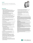
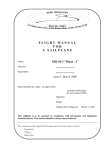
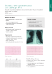
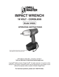
Pacemakers
Accent MRI™ DR
Dual-Chamber Pacemaker
Product Highlights
n
The Accent MRI pacemaker has been designed and tested for safe
performance of a full-body MRI scan, without zone restrictions,1 using a 1,5 T
(Tesla) field-strength MRI scanner.1 The MRI conditional device:
– Allows a maximum whole body averaged specific absorption rate (SAR) of
4 watts per kilogram (W/kg) for high image resolution
– Must be used in conjunction with an MRI lead from St. Jude Medical
n
n
n
™
An optional, easy-to-use hand-held device (SJM MRI Activator device) can be
used to program the device to pre-approved MRI settings pre- and post-MRI
scan, decreasing the number of workflow steps and increasing clinic efficiency
AT/AF Alerts can be programmed to notify patients and/or their clinics when
a programmed AT/AF threshold or continuous episode duration has been
exceeded, or when a high ventricular rate accompanies the AT/AF episode
A suite of state-of-the-art features—complete automaticity (atrial and
ventricular), Ventricular Intrinsic Preference (VIP™) technology, QuickOpt™
timing cycle optimisation, the AF Suppression™ algorithm and SenseAbility ™
technology—is designed to deliver optimal therapy for patients at implant and
throughout their lives
Industry-leading longevity offers 9,4 years of service life,2 which is supported by a 7-year warranty 3
n
1. The St. Jude Medical™ MRI conditional pacing system can be scanned in patients under the following conditions: horizontal closed bore clinical scanner working in the Normal Operating Mode or First Level Controlled Operating Mode; static magnetic field strength of 1,5 Tesla (T) only; maximum gradient slew rate of 200 T/m/s per axis.
See manual for additional details before performing an
MRI scan.
2. A
,V = 2,5 V @ 0,4 ms; 500 ohms; 100% DDD pacing @ 60 bpm;
AutoCapture™ Pacing System OFF; SEGMs ON
3. Terms and conditions apply; refer to the warranty for details.
Ordering Information
Contents: Cardiac pulse generator
Model Number
Dimensions (H x W x T, mm)
Weight (g) Volume (cc) Connector
PM2124 (Inductive) 52 x 53 x 6 23 13,1 (± 0,5)
IS-1
Radiopaque markers
St. Jude Medical identifier
Indications: Implantation of a dual-chamber pulse generator is indicated in one or more of the following
permanent conditions: syncope, presyncope, fatigue, disorientation due to arrhythmia/bradycardia or any
combination of those symptoms. MRI conditional pulse generator is safe for use in the MRI environment
when used in a complete MRI conditional pacing system and according to the instructions in the MRI
Procedure Information document for the St. Jude Medical MRI conditional pacing system. Rate-modulated
pacing is indicated for patients with chronotropic incompetence, and for those who would benefit from
increased stimulation rates concurrent with physical activity. Dual-chamber pacing is indicated for those
patients exhibiting: sick sinus syndrome, chronic, symptomatic second- and third-degree AV block, recurrent
Adams-Stokes syndrome, symptomatic bilateral bundle branch block when tachyarrhythmia and other causes
have been ruled out. Atrial pacing is indicated for patients with sinus node dysfunction and normal AV and
intraventricular conduction systems. Ventricular pacing is indicated for patients with significant bradycardia
and normal sinus rhythm with only rare episodes of A-V block or sinus arrest, chronic atrial fibrillation, severe
physical disability. AF Suppression algorithm is indicated for suppression of paroxysmal or persistent atrial
fibrillation episodes in patients with one or more of the above pacing indications.
Contraindications: Dual-chamber pulse generators are contraindicated in patients with an implanted
cardioverter defibrillator (ICD). Rate-adaptive pacing may be inappropriate for patients who experience angina
or other symptoms of myocardial dysfunction at higher sensor-driven rates. An appropriate Maximum Sensor
Rate should be selected based on assessment of the highest stimulation rate tolerated by the patient. AF
Suppression stimulation is not recommended in patients who cannot tolerate high atrial-rate stimulation.
Dual-chamber pacing, though not contraindicated for patients with chronic atrial flutter, chronic atrial
Customer Support: 46-8-474-4756
Brief Summary: Prior to using these devices, please review the Instructions for Use for a complete listing of
indications, contraindications, warnings, precautions, potential adverse events and directions for use. Devices
depicted may not be available in all countries. Check with your St. Jude Medical representative for product availability
in your country. Unless otherwise noted, ™ indicates that the name is a trademark of, or licensed to, St. Jude
Medical or one of its subsidiaries. ST. JUDE MEDICAL, the nine-squares symbol and MORE CONTROL. LESS RISK.
are registered and unregistered trademarks and service marks of St. Jude Medical, Inc. and its related companies.
©2011 St. Jude Medical, Inc. All rights reserved.
Device MRI symbol
fibrillation, or silent atria, may provide no benefit beyond that of single-chamber pacing in such patients.
Single-chamber ventricular demand pacing is relatively contraindicated in patients who have demonstrated
pacemaker syndrome, have retrograde VA conduction, or suffer a drop in arterial blood pressure with the
onset of ventricular pacing. Single-chamber atrial pacing is relatively contraindicated in patients who have
demonstrated compromise of AV conduction.
Adverse Events: The following are potential complications associated with the use of any pacing system:
arrhythmia, heart block, thrombosis, threshold elevation, valve damage, pneumothorax, myopotential sensing,
vessel damage, air embolism, body rejection phenomena, cardiac tamponade or perforation, formation of
fibrotic tissue, local tissue reaction, inability to interrogate or program a device because of programmer
malfunction, infection, interruption of desired device function due to electrical interference, loss of desired
pacing and/or sensing due to lead displacement, body reaction at electrode interface, or lead malfunction
(fracture or damage to insulation), loss of normal device function due to battery failure or component
malfunction, device migration, pocket erosion, or hematoma, pectoral muscle stimulation, and phrenic nerve
or diaphragmatic stimulation. The following, in addition to the above, are potential complications associated
with the use of rate-modulated pacing systems: inappropriate, rapid pacing rates due to sensor failure or
to the detection of signals other than patient activity, loss of activity-response due to sensor failure, and
palpitations with high-rate pacing.
Refer to the User’s Manual for more detailed indications, contraindications, warnings, precautions and
potential adverse events.
Pacemakers
Accent MRI™ DR
Dual-Chamber Pacemaker
Product Specifications
PHYSICAL SPECIFICATIONS
ModelPM2124
TelemetryInductive
Dimensions (mm) 52 x 53 x 6
Weight (g) 23
Volume (cc) 13,11
Connector IS-1
PARAMETER SETTINGS
Rate/Timing
Atrial Pace Refractory (ms) Atrial Sense Refractory (ms) Atrial Protection Interval (ms) Paced AV Delay (ms) Base Rate (min-1) Far-Field Protection Interval (ms) Hysteresis Rate (min-1) Search Interval (min) Cycle Count Intervention Rate (min-1) Intervention Duration (min) Recovery Time Maximum Tracking Rate (min-1) Mode Post-Ventricular Atrial Blanking (ms) PVARP (ms) Sensed AV Delay (ms) Rest Rate (min-1) Shortest AV Delay (ms) Ventricular Blanking (ms) Ventricular Pace/Sense Refractory5
(Fixed) (ms) 190-400 in steps of 30; 440; 4702
93; 125; 157; 190-400 in steps of 30; 440; 470; 5002
1253
25; 30-200 in steps of 10; 225-300 in steps of 25; 350
30-130 in steps of 5; 140-170 in steps of 10
163
Off; 30 4-150 in steps of 5
Off; 1; 5; 10; 15; 30
1-16 in steps of 1
Off; Same as Base Rate; 80-120 in steps of 10; Intrinsic +0;
Intrinsic +10; Intrinsic +20; Intrinsic +30
1-10 in 1-minute intervals
Fast; Medium; Slow; Very Slow
90-130 in steps of 5; 140-180 in steps of 10
AOO(R); AAI(R); AAT(R); VOO(R); VVI(R);
VVT(R); VDD(R); DOO(R); DVI(R); DDI(R);
DDD(R); Pacing Off
60-200 in steps of 10; 225; 250
125-500 in steps of 25
25; 30-200 in steps of 10; 225-325 in steps of 25
Off; 30-150 in steps of 5
25-50 in steps of 5; 60-120 in steps of 10
Auto; 12-52 in steps of 4
125; 160-400 in steps of 30; 440; 4702
MRI Settings
MRI Mode
MRI Base Rate MRI Paced AV Delay
MRI Atrial Pulse Configuration
MRI Atrial Pulse Amplitude
MRI Atrial Pulse Width
MRI RV Pulse Configuration
MRI RV Pulse Amplitude
MRI RV Pulse Width AOO; VOO; DOO; Pacing Off
30-120 bpm in steps of 5 bpm
25 ms; 30-200 ms in steps of 10 ms;
225-300 ms in steps of 25 ms; 350 ms
Bipolar
5,0 V; 7,5 V
1,0 ms
Bipolar
5,0 V; 7,5 V
1,0 ms
Output/Sensing
ACap™ Confirm On; Off; Monitor
Primary Pulse Configuration Bipolar
Backup Pulse Configuration Bipolar
Backup Pulse Amplitude (V) 5,0
Search Interval (hours) 8; 24
A or V Pulse Amplitude (V) 0,25-4,0 in steps of 0,25; 4,5-7,5 in steps of 0,5
A or V Pulse Width (ms) 0,05; 0,1-1,5 in steps of 0,1
A or V Pulse Configuration Unipolar (tip-case); Bipolar (tip-ring)
A or V Sense Configuration Unipolar Tip (tip-case); Bipolar (tip-ring);
Unipolar Ring (ring-case)
Atrial Sensitivity (mV) 0,1-0,46 in steps of 0,1; 0,5; 0,75-2,0 in steps of 0,25;
2,5-4,0 in steps of 0,5; 5,07
™
Ventricular AutoCapture Pacing System On; Off
Primary Pulse Configuration Unipolar; Bipolar
Backup Pulse Configuration Unipolar; Bipolar
Backup Pulse Amplitude (V) 5,03
Search Interval (hours) 8; 24
AutoCapture
Paced/Sensed AV Delay (ms) 50/25; 100/70; 120/100
Ventricular Sensitivity (mV) 0,5-5,0 in steps of 0,5; 6-10 in steps of 1,0; 12,57
™
SenseAbility Technology
Off; On (Automatic Sensitivity Control adjustment for atrial
and ventricular events)
A Max Sensitivity (mV)
0,2-1,0 in steps of 0,1
V Max Sensitivity (mV) 0,2-2,0 in steps of 0,1
Threshold Start
(Atrial and Ventricular Post-Sense) 50; 62,5; 75; 100%
(Atrial Post-Pace) 0,2-3,0 in steps of 0,1 mV
(Ventricular Post-Pace) Auto; 0,2-3,0 in steps of 0,1 mV
Decay Delay (ms)
(Atrial and Ventricular Post-Sense) 0; 30; 60; 95; 125; 160; 190; 220
(Atrial Post-Pace) 0; 30; 60; 95; 125; 160; 190; 220
(Ventricular Post-Pace) Auto; 0; 30; 60; 95; 125; 160; 190; 220
(GMCRM739EN)
Rate-Modulated Parameters
Maximum Sensor Rate (min-1) Rate Responsive AV Delay Rate Responsive PVARP/VREF Reaction Time Recovery Time 80-150 in steps of 5; 160-180 in steps of 10
Off; Low; Medium; High
Off; Low; Medium; High
Very Fast; Fast; Medium; Slow
Fast; Medium; Slow; Very Slow
Customer Support: 46-8-474-4756
Brief Summary: Prior to using these devices, please review the Instructions for Use for a complete listing of
indications, contraindications, warnings, precautions, potential adverse events and directions for use. Devices
depicted may not be available in all countries. Check with your St. Jude Medical representative for product availability
in your country. Unless otherwise noted, ™ indicates that the name is a trademark of, or licensed to, St. Jude
Medical or one of its subsidiaries. ST. JUDE MEDICAL, the nine-squares symbol and MORE CONTROL. LESS RISK.
are registered and unregistered trademarks and service marks of St. Jude Medical, Inc. and its related companies.
©2011 St. Jude Medical, Inc. All rights reserved.
Item GMCRM739EN
Sensor Shortest PVARP/VREF (ms) Slope Threshold AF Management
On; Off; Passive
125-475 in steps of 25
Auto (-1); Auto (+0); Auto (+1); Auto (+2);
Auto (+3); 1-16 in steps of 1
Auto (-0,5); Auto (+0,0); Auto (+0,5); Auto (+1,0);
Auto (+1,5); Auto (+2,0); 1-7 in steps of 0,5
Off; On
AF Suppression™ Algorithm 103
Lower Rate Overdrive (min-1) -1
Upper Rate Overdrive (min ) 53
No. of Overdrive Pacing Cycles 15-40 in steps of 5
Rate Recovery (ms) 8; 123
Maximum AF
80-150 in steps of 5; 160-180 in steps of 10
Suppression Rate (min-1) Atrial Tachycardia
-1
110-200 in steps of 10; 225-300 in steps of 25
Detection Rate (min ) Auto Mode Switch Off; DDD(R) to DDI(R); DDD(R) to DDT(R); DDD(R) to VVI(R);
DDD(R) to VVT(R); VDD(R) to VVI(R); VDD(R) to VVT(R)
-1
40-170 in steps of 5
AMS Base Rate (min ) Stored Electrograms
Options
Priority Options Channel Triggers
Advanced Hysteresis AMS Entry/AMS Exit/
AMS Entry and Exit AT/AF Detection Magnet Response High Atrial Rate
Rate (min-1)
No. of Consecutive Cycles High Ventricular Rate
Rate (min-1)
No. of Consecutive Cycles
PMT Termination Consecutive PVCs No. of Consecutive PVCs Noise Reversion Off; Low; High
1; 2; 3
Off; Low; High
Off; Low; High
Off; Low; High
Off; Low; High
Off; Low; High
125-300 in steps of 25
2; 3; 4; 5; 10; 15; 20
Off; Low; High
125-300 in steps of 25
2; 3; 4; 5; 10; 15; 20
Off; Low; High
Off; Low; High
2; 3; 4; 5
Off; Low; High
Other
A and V Lead Monitoring A and V Low Impedance Limit (Ω) A and V High Impedance Limit (Ω) Lead Type Magnet Response Negative AV Hysteresis Search (ms) NIPS Options
Stimulation Chamber Coupling Interval (ms) S1 Count S19; S2; S3 and S4 Cycle (ms) Ventricular Support Rate (min-1) Sinus Node Recovery Delay (sec) PMT Options PMT Detection Rate (min-1) PVC Response Ventricular Intrinsic
Preference, VIP™ (ms) VIP Search Interval VIP Search Cycles Ventricular Safety Standby Diagnostic Trends
Monitor; Auto Polarity Switch
100-500 in steps of 25
750-2500 in steps of 250; 3000
Uncoded; Unipolar; Bipolar
Off; Battery Test
Off; -10 to -120 in steps of 10
Atrial; Ventricular
100-800 in steps of 108
2-25 in steps of 1
Off; 100-800 in steps of 10 (Fixed or Adaptive)
Off; 30-95 in steps of 5
1; 2; 3; 4; 5
Off; Passive; Atrial Pace2
90-180 in steps of 5
Off; Atrial Pace2
Off; 50-150 in steps of 25; 160-200 in steps of 10
30 sec; 1; 3; 5; 10; 30 min
1; 2; 3
Off; On
AT/AF Activity; Exercise; Lead Impedance; P and R Wave; A and V Threshold
Patient Notifiers
Programmable Notifiers (On; Off) Device at ERI; Atrial Lead Impedance Out of Range;
Ventricular Lead Impedance Out of Range; AT/AF Burden;
AT/AF Episode Duration; V Rate During AT/AF (High V Rate Threshold/
Total Time in High V Rate)
Device Reset On
Entry into Backup VVI Mode On
Audible Duration (sec) 2; 4; 6; 8; 10; 12; 14; 16
Number of Audible Alerts
per Notification 2
Number of Notifications 1-16
Time Between Notifications (hours) 10; 22
1. ± 0,5 cc
2. Programming options dependent on pacing mode.
3. This parameter is not programmable.
4. The highest available setting for hysteresis rate will be 5 min-1 below the programmed base rate.
5. In dual-chamber modes, the maximum ventricular refractory period is 325 ms.
6. Values 0,1-0,4 not available in a unipolar sense configuration.
7. Sensitivity is with respect to a 20 ms haversine test signal.
8. During atrial NIPS in dual-chamber modes, the shortest Coupling Interval will be limited by the programmed AV/PV delay.
9. S1 Burst Cycle is applied at the pre-programmed S1 cycle length.
Pacemakers
Accent MRI™ SR
Single-Chamber Pacemaker
Product Highlights
n The Accent MRI pacemaker has been designed and tested for safe performance of a full-body MRI scan, without zone restrictions,1 using a 1,5 T (Tesla) field-strength MRI scanner.1 The MRI conditional device:
– Allows a maximum whole body averaged specific absorption rate (SAR) of
4 watts per kilogram (W/kg) for high image resolution
– Must be used in conjunction with an MRI lead from St. Jude Medical
n
n
An optional, easy-to-use hand-held device (SJM MRI Activator device)
can be used to program the device to pre-approved MRI settings pre- and
post-MRI scan, decreasing the number of workflow steps and increasing
clinic efficiency
™
State-of-the-art features—such as automaticity, Ventricular AutoCapture™
Pacing System and SenseAbility ™ technology—are designed to deliver optimal
therapy for patients at implant and throughout their lives
Industry-leading longevity offers 14,2 years of service life,2 which is supported by a 7-year warranty3
n
1. The St. Jude Medical™ MRI conditional pacing system can be scanned in patients under the following conditions: horizontal closed bore clinical scanner working in the Normal Operating Mode or First Level Controlled Operating Mode; static magnetic field strength of 1,5 Tesla (T) only; maximum gradient slew rate of 200 T/m/s per axis.
See manual for additional details before performing an
MRI scan.
2. V
= 2,5 V @ 0,4 ms; 500 ohms; 100% VVI pacing @ 60 bpm;
AutoCapture Pacing System OFF; SEGMs ON
3. Terms and conditions apply; refer to the warranty for details.
Ordering Information
Contents: Cardiac pulse generator
Model Number
Dimensions (H x W x T, mm)
Weight (g) Volume (cc) Connector
PM1124 (Inductive) 46 x 52 x 6 22
12 (± 0,5)
IS-1
Radiopaque markers
St. Jude Medical identifier
Indications: Implantation of a single-chamber pulse generator is indicated in one or more of the following
permanent conditions: syncope, presyncope, fatigue, disorientation due to arrhythmia/bradycardia or any
combination of those symptoms. MRI conditional pulse generator is safe for use in the MRI environment when
used in a complete MRI conditional pacing system and according to the instructions in the MRI Procedure
Information document for the St. Jude Medical MRI conditional pacing system. Rate-modulated pacing is
indicated for patients with chronotropic incompetence, and for those who would benefit from increased
stimulation rates concurrent with physical activity. Atrial pacing is indicated for patients with sinus node
dysfunction and normal AV and intraventricular conduction systems. Ventricular pacing is indicated for
patients with significant bradycardia and normal sinus rhythm with only rare episodes of A-V block or sinus
arrest, chronic atrial fibrillation, severe physical disability.
Contraindications: Single-chamber pulse generators are contraindicated in patients with an implanted
cardioverter defibrillator (ICD). Rate-adaptive pacing may be inappropriate for patients who experience
angina or other symptoms of myocardial dysfunction at higher sensor-driven rates. An appropriate Maximum
Sensor Rate should be selected based on assessment of the highest stimulation rate tolerated by the patient.
Single-chamber ventricular demand pacing is relatively contraindicated in patients who have demonstrated
pacemaker syndrome, have retrograde VA conduction, or suffer a drop in arterial blood pressure with the
onset of ventricular pacing. Single-chamber atrial pacing is relatively contraindicated in patients who have
demonstrated compromise of AV conduction.
Customer Support: 46-8-474-4756
Brief Summary: Prior to using these devices, please review the Instructions for Use for a complete listing of
indications, contraindications, warnings, precautions, potential adverse events and directions for use. Devices
depicted may not be available in all countries. Check with your St. Jude Medical representative for product availability
in your country. Unless otherwise noted, ™ indicates that the name is a trademark of, or licensed to, St. Jude
Medical or one of its subsidiaries. ST. JUDE MEDICAL, the nine-squares symbol and MORE CONTROL. LESS RISK.
are registered and unregistered trademarks and service marks of St. Jude Medical, Inc. and its related companies.
©2011 St. Jude Medical, Inc. All rights reserved.
Device MRI symbol
Adverse Events: The following are potential complications associated with the use of any pacing system:
arrhythmia, heart block, thrombosis, threshold elevation, valve damage, pneumothorax, myopotential sensing,
vessel damage, air embolism, body rejection phenomena, cardiac tamponade or perforation, formation of
fibrotic tissue, local tissue reaction, inability to interrogate or program a device because of programmer
malfunction, infection, interruption of desired device function due to electrical interference, loss of desired
pacing and/or sensing due to lead displacement, body reaction at electrode interface, or lead malfunction
(fracture or damage to insulation), loss of normal device function due to battery failure or component
malfunction, device migration, pocket erosion, or hematoma, pectoral muscle stimulation, and phrenic nerve
or diaphragmatic stimulation. The following, in addition to the above, are potential complications associated
with the use of rate-modulated pacing systems: inappropriate, rapid pacing rates due to sensor failure or
to the detection of signals other than patient activity, loss of activity-response due to sensor failure, and
palpitations with high-rate pacing.
Refer to the User’s Manual for more detailed indications, contraindications, warnings, precautions and
potential adverse events.
Pacemakers
Accent MRI™ SR
Single-Chamber Pacemaker
Product Specifications
PHYSICAL SPECIFICATIONS
Stored Electrograms
ModelPM1124
TelemetryInductive
Dimensions (mm) 46 x 52 x 6
Weight (g) 22
Volume (cc) 121
Connector IS-1
Options
Priority Options Channel Triggers
Magnet Response High Ventricular Rate Rate (min-1) No. of Consecutive Cycles Advanced Hysteresis Noise Reversion PARAMETER SETTINGS
Rate/Timing
Ventricular Pace/Sense Refractory
(Fixed) (ms)
Base Rate (min-1) Mode Hysteresis Rate (min-1) Search Interval (min-1) Cycle Count Intervention Rate (min-1) Intervention Duration (min) Recovery Time Rest Rate (min-1) 125; 160-400 in steps of 30; 440; 470; 5002
30-130 in steps of 5; 140-170 in steps of 10
VOO(R); VVI(R); VVT(R); Pacing Off
Off; 303-150 in steps of 5
Off; 1; 5; 10; 15; 30
1-16 by 1
Off; Same as Base Rate; 80-120 in steps of 10; Intrinsic +0;
Intrinsic +10; Intrinsic +20; Intrinsic +30
1-10 in 1 minute intervals
Fast; Medium; Slow; Very Slow
Off; 30-150 in steps of 5
MRI Settings
MRI Mode
MRI Base Rate MRI RV Pulse Configuration
MRI RV Pulse Amplitude
MRI RV Pulse Width VOO; Pacing Off
30-120 bpm in steps of 5 bpm
Bipolar
5,0 V; 7,5 V
1,0 ms
Output/Sensing
V Pulse Amplitude (V) V Pulse Width (ms) V Sensitivity (mV) V Pulse Configuration V Sense Configuration Ventricular AutoCapture™
Pacing System Primary Pulse Configuration Backup Pulse Configuration Backup Pulse Amplitude (V) Search Interval (hours) SenseAbility™ Technology
Max Sensitivity (mV)
Threshold Start
Decay Delay (ms)
0,25-4,0 in steps of 0,25; 4,5-7,5 in steps of 0,5
0,05; 0,1-1,5 in steps of 0,1
0,5-5,0 in steps of 0,5; 6-10 in steps of 1,0; 12,5 4
Unipolar (tip-case); Bipolar (tip-ring)
Unipolar Tip (tip-case); Bipolar (tip-ring); Unipolar Ring (ring-case)
On; Off
Unipolar; Bipolar
Unipolar; Bipolar
5,05
8; 24
Off; On (Automatic Sensitivity Control adjustment for ventricular events)
0,2-2,0 in steps of 0,1
(Ventricular Post-Sense) 50; 62,5; 75; 100%
(Ventricular Post-Pace) Auto; 0,2-3,0 in steps of 0,1 mV
(Ventricular Post-Sense) 0; 30; 60; 95; 125; 160; 190; 220
(Ventricular Post-Pace) Auto; 0; 30; 60; 95; 125; 160; 190; 220
Rate-Modulated Parameters
Maximum Sensor Rate (min-1) Rate Responsive VREF Shortest VREF Reaction Time Recovery Time Sensor Slope Threshold 80-150 in steps of 5; 160-180 in steps of 10
Off; Low; Medium; High
125-475 in steps of 25
Very Fast; Fast; Medium; Slow
Fast; Medium; Slow; Very Slow
On; Off; Passive
Auto (-1); Auto (+0); Auto (+1); Auto (+2); Auto (+3); 1-16 in steps of 1
Auto (-0,5); Auto (+0,0); Auto (+0,5); Auto (+1,0); Auto (+1,5);
Auto (+2,0); 1-7 in steps of 0,5
Customer Support: 46-8-474-4756
Brief Summary: Prior to using these devices, please review the Instructions for Use for a complete listing of
indications, contraindications, warnings, precautions, potential adverse events and directions for use. Devices
depicted may not be available in all countries. Check with your St. Jude Medical representative for product availability
in your country. Unless otherwise noted, ™ indicates that the name is a trademark of, or licensed to, St. Jude
Medical or one of its subsidiaries. ST. JUDE MEDICAL, the nine-squares symbol and MORE CONTROL. LESS RISK.
are registered and unregistered trademarks and service marks of St. Jude Medical, Inc. and its related companies.
©2011 St. Jude Medical, Inc. All rights reserved.
Item GMCRM740EN
Off; Low; High
1; 2; 3
Off; Low; High
Off; Low; High
125-300 in steps of 25
2; 3; 4; 5; 10; 15; 20
Off; Low; High
Off; Low; High
Other
Lead Monitoring V Low Impedance Limit (Ω) V High Impedance Limit (Ω) Magnet Response Lead Type NIPS Options
Stimulation Chamber Coupling Interval (ms) S1 Count S16 ; S2; S3 and S4 Cycle (ms) Diagnostic Trends
Monitor; Auto Polarity Switch
100-500 in steps of 25
750-2500 in steps of 250; 3000
Off; Battery Test
Uncoded; Unipolar; Bipolar
Ventricular
100-800 in steps of 10
2-25 in steps of 1
100-800 in steps of 10 (Fixed or Adaptive)
Exercise; Lead Impedance; R Wave; V Threshold
Patient Notifiers
Programmable Notifiers (On; Off) Device Reset Entry into Backup VVI Mode Audible Duration (sec) Number of Audible Alerts
per Notification Number of Notifications Time Between Notifications (hours) Device at ERI; Ventricular Lead Impedance Out of Range
On
On
2; 4; 6; 8; 10; 12; 14; 16
2
1-16
10; 22
1. ± 0,5 cc
2. Programming options dependent on pacing mode.
3. The highest available setting for hysteresis rate will be 5 min-1 below the programmed base rate.
4. Sensitivity is with respect to a 20 ms haversine test signal.
5. This parameter is not programmable.
6. S1 Burst Cycle is applied at the preprogrammed S1 cycle length.
Handheld MRI Pacemaker Settings Activator
SJM MRI Activator™
Handheld Device
Product Highlights
n
n
The SJM MRI Activator™ handheld device, model EX4000, is an external device
that uses radio waves to communicate with a St. Jude Medical MRI conditional
implanted pulse generator
The SJM MRI Activator device streamlines MRI patient workflow by allowing
previously stored MRI settings to be easily:
– Enabled before an MRI scan1
– Disabled after an MRI scan1
– Verified at any time
Ordering Information
Contents: SJM MRI Activator device
Reorder Number
Description
EX4000
SJM MRI Activator EX4000
Intended Use: The SJM MRI Activator™ handheld device is used to evaluate the status of, and to enable
and disable, the previously stored MRI settings. The activator is intended for use with St. Jude Medical™ MR
Conditional pulse generators.
Contraindications: There are no contraindications.
Warnings and Precautions: Electromagnetic interference. The activator is not magnetic and has no
moving parts. However, you should avoid equipment which generates a strong electromagnetic interference
(EMI). EMI could interfere with communication between the activator and the implanted St. Jude Medical ™
MR conditional pulse generator. Moving away from the source of EMI or turning it off will usually allow the
activator to return to its normal mode of operation. Communication equipment. Communication equipment
such as microwave transmitters or high-power amateur transmitters may generate enough EMI to interfere
Customer Support: 46-8-474-4756
Brief Summary: Prior to using these devices, please review the Instructions for Use for a complete listing of
indications, contraindications, warnings, precautions, potential adverse events and directions for use. Devices
depicted may not be available in all countries. Check with your St. Jude Medical representative for product availability
in your country. Unless otherwise noted, ™ indicates that the name is a trademark of, or licensed to, St. Jude
Medical or one of its subsidiaries. ST. JUDE MEDICAL, the nine-squares symbol and MORE CONTROL. LESS RISK.
are registered and unregistered trademarks and service marks of St. Jude Medical, Inc. and its related companies.
©2011 St. Jude Medical, Inc. All rights reserved.
with the performance of the activator if you are too close to the source of EMI. Wireless communication
devices. Wireless communication devices such as computers that operate on a wireless network, handheld
personal computers (PDA), cellular phones, and even cordless telephones may generate enough EMI to
interfere with the performance of the activator if it is used too close to the source of EMI. Hospital and Medical
equipment. A variety of standard hospital and medical equipment may generate enough EMI to interfere
with the performance of the activator. These include, but are not limited to: blood pressure monitors, ECG
equipment, external defibrillation equipment, x-ray machines. Office equipment. A variety of standard office
equipment may generate enough EMI to interfere with the performance of the activator. These include, but
are not limited to: desktop or laptop computers, fax machines, phone systems. Industrial equipment. A variety
of industrial equipment may generate enough EMI to interfere with the performance of your activator. These
include, but are not limited to: arc welders; induction furnaces; very large or defective electric motors; and
internal combustion engines with poorly shielded ignition systems.
Handheld MRI Pacemaker Settings Activator
SJM MRI Activator™
Handheld Device
Product Specifications
PHYSICAL SPECIFICATIONS
ModelEX4000
Dimensions (cm) 7,1 x 5,6 x 1,8
Case material High-impact plastic
Power source 1 cell; 3,6 V (nominal); Chemistry:
Lithium Thionyl Chloride
Battery longevity 3 years from manufacturing date
Audible output level 60 dB (minimum) at 10,0 cm
Classification with respect to electric shock
Internally powered
Protection from electric shock (IEC 60601-1)
Protection against ingress of liquids
Mode of operation
Type BF
Ordinary equipment
Non-continuous
(GMCRM855EN)
1. T he SJM MRI Activator device is designed to enable/disable pre-programmed MRI mode quickly and easily pre- and post-scan;
do not take the SJM MRI Activator device into the MRI magnet/scanner room.
Customer Support: 46-8-474-4756
Brief Summary: Prior to using these devices, please review the Instructions for Use for a complete listing of
indications, contraindications, warnings, precautions, potential adverse events and directions for use. Devices
depicted may not be available in all countries. Check with your St. Jude Medical representative for product availability
in your country. Unless otherwise noted, ™ indicates that the name is a trademark of, or licensed to, St. Jude
Medical or one of its subsidiaries. ST. JUDE MEDICAL, the nine-squares symbol and MORE CONTROL. LESS RISK.
are registered and unregistered trademarks and service marks of St. Jude Medical, Inc. and its related companies.
©2011 St. Jude Medical, Inc. All rights reserved.
Item GMCRM855EN
Pacing Leads
Tendril MRI™
Pacing Lead
Product Highlights
n
The Tendril MRI lead is designed to ensure patient safety while performing
an MRI scan1
– The Tendril MRI conditional lead must be used in conjunction with an
MRI device from St. Jude Medical and with a 1,5 T (Tesla) MRI scanner
n
Soft silicone tip offers more compliance at the lead tip-endocardium interface
– The soft silicone tip on the Tendril MRI LPA1200M lead reduces tip
pressure by approximately 50% over 6 F leads without a soft silicone tip2
Though the soft silicone increases the surface area of the lead tip to 9 F,
the Tendril MRI lead still fits through an 8 F introducer due to the material’s
soft nature. Four pads on the silicone tip further increase the surface area
of the lead tip that is in contact with the tissue
n
n
Optim™ lead insulation—a chemical co-polymer that blends the best features
of polyurethane and silicone—provides improved handling and increased
durability
Limited lifetime warranty
– Terms and conditions apply. Refer to the warranty for details
1. See manual for additional details before performing an MRI scan.
2. Bench testing data on file.
Ordering Information
Contents: Cardiac pacing lead
Insulation
Fixation
Min. Introducer (F)
Connector
Length (cm)
LPA1200M
Optim
Ext/Ret helix
8
IS-1 bipolar
46, 52 and 58
t
Easily identifiable unique
radiopaque markers
t
Model Number
Indications: The Tendril MRI™ lead is designed for permanent sensing and pacing in either the right atrium or
the right ventricle, in combination with a compatible device.
Active leads such as the Tendril MRI lead may be indicated for patients where permanent fixation of passive
leads is suspected to be unstable. In atrial applications, the use of a screw-in lead such as Tendril MRI lead
may be indicated in the presence of an abnormal, surgically altered or excised atrial appendage.
This is an MR Conditional lead.
MR Conditional Pacing System: The St. Jude Medical MRI conditional lead is part of the St. Jude Medical™ MRI
conditional pacing system. Patients with an implanted St. Jude Medical™ MRI conditional pacing system can
have an MRI scan if the conditions for use, as described in the MRI Procedure Information document, are met.
Customer Support: 46-8-474-4756
Brief Summary: Prior to using these devices, please review the Instructions for Use for a complete listing of
indications, contraindications, warnings, precautions, potential adverse events and directions for use. Devices
depicted may not be available in all countries. Check with your St. Jude Medical representative for product availability
in your country. Unless otherwise noted, ™ indicates that the name is a trademark of, or licensed to, St. Jude
Medical or one of its subsidiaries. ST. JUDE MEDICAL, the nine-squares symbol and MORE CONTROL. LESS RISK.
are registered and unregistered trademarks and service marks of St. Jude Medical, Inc. and its related companies.
©2011 St. Jude Medical, Inc. All rights reserved.
Contraindications: The Tendril MRI™ lead is contraindicated in the presence of tricuspid atresia, for patients
with mechanical tricuspid valves, and in patients who are expected to be hypersensitive to a single dose of one
milligram of dexamethasone sodium phosphate.
Adverse Events: Potential complications associated with the use of Tendril MRI leads are the same as with
the use of other active fixation leads and include: perforation of the myocardium, cardiac tamponade, phrenic
nerve stimulation, dislodgement of the pacing lead, embolism, temporary or permanent loss of stimulation
and/or sensing, infection, valve and/or vessel damage, tissue necrosis.
Refer to the User’s Manual for more detailed indications, contraindications, warnings, precautions and
potential adverse events.
Pacing Leads
Tendril MRI™
Pacing Lead
Product Specifications
PHYSICAL SPECIFICATIONS
ModelLPA1200M
Minimum Introducer Size
8F
Minimum Introducer Size with Guidewire
10,5 F
Type of Lead
Active-fixation, steroid-eluting, endocardial, straight pacing lead
Lead Connector
IS-1 bipolar
Lead Lengths
46, 52 and 58 cm
Fixation Mechanism
Extendable/Retractable helix
Typical Number of Rotations
for Helix Extension
5-10 (straight stylet)
Lead Body Diameter
2,18 mm (max)/6,6 F
Tip-to-Ring Spacing
10 mm
Lead Tip Electrode (Cathode)
Active TiN-coated Pt/Ir helix (1,8 mm extension)
Tip Electrode Surface Area
6,8 mm2
Ring Electrode (Anode)
TiN-coated Pt/Ir
Ring Electrode Surface Area
16,5 mm2
Mapping
Capable with TiN-coated Pt/Ir helix
Steroid
Silicone plug with <1 mg dexamethasone sodium phosphate
Inner Conductor/Outer Conductor
MP35N™* coil
Inner Insulation
Silicone
Outer Insulation
Optim™ lead insulation
In Pack
Straight stylets
J-shaped stylets
Helix extension/retraction clip-on tools
Accessory Kits
Available Separately
Model Number 1 x-soft in lead, 1 x-soft, 1 soft
2 soft
2 clip-on tools
Compatible Lengths Description
Stylet Kit DSO6002 with appropriate
46, 52 and 58 cm 1 fixation tool, 1 clip-on tool,
length designation
1 J-shaped soft, 1 x-soft,
1 soft, 1 firm, 1 x-firm
DSO6003 with appropriate 46, 52 and 58 cm
1 clip-on tool, 1 J-shaped soft,
length designation
1 x-soft, 1 soft, 1 firm, 1 x-firm
1281 with appropriate 46, 52 and 58 cm
Disposable implant tool to Locator™ Plus Deflectable Stylet
length designation
facilitate precise lead positioning 1292 with appropriate
46, 52 and 58 cm
and manipulation with one hand
length designation
(GMCRM741EN)
*MP35N is a trademark of SPS Technologies, Inc.
Customer Support: 46-8-474-4756
Brief Summary: Prior to using these devices, please review the Instructions for Use for a complete listing of
indications, contraindications, warnings, precautions, potential adverse events and directions for use. Devices
depicted may not be available in all countries. Check with your St. Jude Medical representative for product availability
in your country. Unless otherwise noted, ™ indicates that the name is a trademark of, or licensed to, St. Jude
Medical or one of its subsidiaries. ST. JUDE MEDICAL, the nine-squares symbol and MORE CONTROL. LESS RISK.
are registered and unregistered trademarks and service marks of St. Jude Medical, Inc. and its related companies.
©2011 St. Jude Medical, Inc. All rights reserved.
Item GMCRM741EN