1
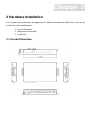
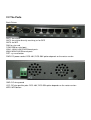
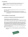
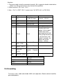
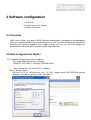
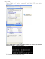
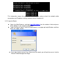
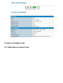
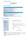
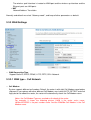
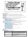
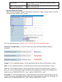
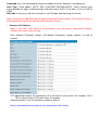
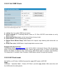
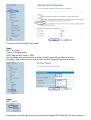
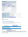
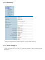
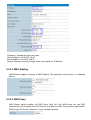
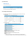
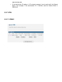
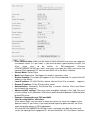
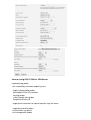
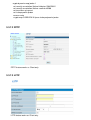
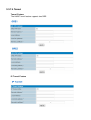
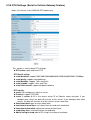
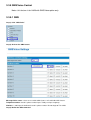
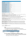
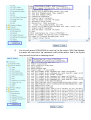
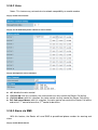
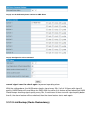
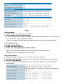
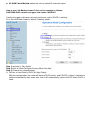
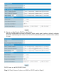
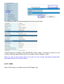
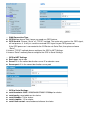
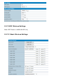
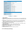
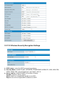
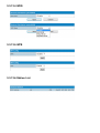
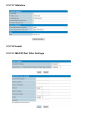
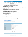
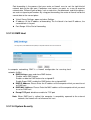
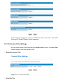
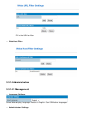
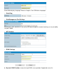
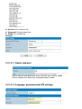
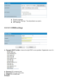
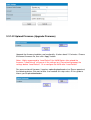
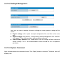
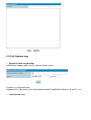
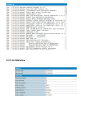
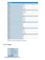
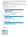
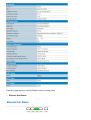
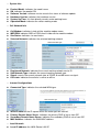
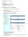
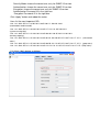
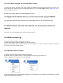
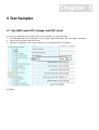
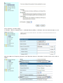
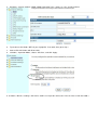
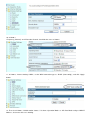
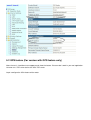
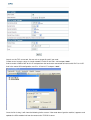
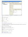
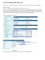
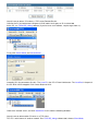
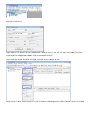
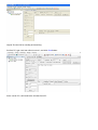
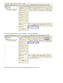
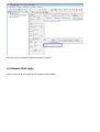
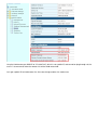
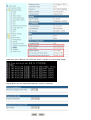
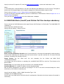
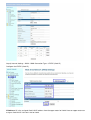
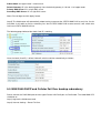
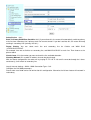
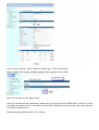
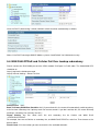
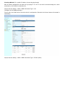
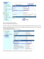
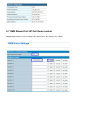
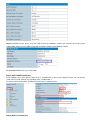
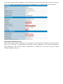
H820 Series Industrial Grade Cellular Router
User Manual
Content
1 Preparation job before configuration ······························································································································· 4
1.1 Learn your router version and feature ················································································································· 4
1.2 Prepare SIM Card and working condition ··········································································································· 5
2 Hardware Installation ························································································································································· 6
2.1 Overall Dimension ·················································································································································· 6
2.2 The Ports ·································································································································································· 7
2.3 Installment································································································································································ 8
2.4 SIM/UIM card installed ··········································································································································· 8
2.5 The installation of terminal blocks ························································································································ 8
2.6 Grounding ································································································································································ 9
2.7 Power Supply ························································································································································ 10
2.8 LED and Check Network Status ························································································································· 10
3 Software configuration····················································································································································· 12
3.1 Overview ································································································································································ 12
3.2 How to log into the Router ··································································································································· 12
3.3 How to configure web··········································································································································· 15
3.3.1 Main Menu as below Picture···························································································································· 15
3.3.2 Operation Mode ················································································································································· 16
3.3.3 WAN Settings ····················································································································································· 17
3.3.3.1 WAN type – Cell Network ····························································································································· 17
3.3.3.2 Cell ICMP Check ············································································································································ 21
3.3.3.3 AP Client mode ··············································································································································· 21
3.3.4 LAN Settings ······················································································································································ 24
3.3.4.1 Router Gateway IP········································································································································· 24
3.3.4.2 MAC binding ··················································································································································· 25
3.3.4.3 DNS Proxy ······················································································································································ 25
3.3.5 DHCP Client ······················································································································································· 26
3.3.6 Configure Static Routing··································································································································· 26
3.3.7 VPN ····································································································································································· 27
3.3.7.1 IPSEC ······························································································································································ 27
3.3.7.2 PPTP ································································································································································ 30
3.3.7.3 L2TP································································································································································· 30
3.3.7.4 Tunnel ······························································································································································ 31
3.3.8 DTU Settings (Serial to Cellular Gateway Feature) ····················································································· 32
3.3.9 SMS/Voice Control ············································································································································ 33
3.3.9.1 SMS·································································································································································· 33
3.3.9.2 Voice ································································································································································ 36
3.3.9.3 Alarm via SMS ················································································································································ 36
3.3.10 Link Backup (Route Redundancy) ················································································································ 37
3.3.11 GPS ··································································································································································· 41
3.3.12 WiFi Wireless Settings ··································································································································· 43
3.3.12.1 Basic Wireless Settings ······························································································································ 43
3.3.12.2 WiFi Advanced Settings ······························································································································ 44
3.3.12.3 Wireless Security/Encryption Settings ······································································································ 45
3.3.12.4 WDS······························································································································································· 46
3.3.12.5 WPS ······························································································································································· 46
3.3.12.6 Station List····················································································································································· 46
3.3.12.7 Statistics ························································································································································ 47
3.3.13 Firewall······························································································································································ 47
3.3.13.1 MAC/IP/Port Filter Settings ························································································································ 47
3.3.13.2 Port Forwarding (Virtual Server Settings) ································································································ 48
3.3.13.3 DMZ Host ······················································································································································ 49
3.3.13.4 System Security ··········································································································································· 49
3.3.13.5 Content Filter Settings································································································································· 50
3.3.14 Administration ·················································································································································· 51
3.3.14.1 Management ················································································································································· 51
3.3.14.1.1 Router web port ········································································································································ 53
3.3.14.1.2 Language, password and NTP settings ································································································ 53
3.3.14.1.3 DDNS settings··········································································································································· 54
3.3.14.2 Upload Firmware (Upgrade Firmware) ····································································································· 55
3.3.14.3 Settings Management ································································································································· 56
3.3.14.4 System Command ······································································································································· 56
3.3.14.5 System Log ··················································································································································· 57
3.3.14.6 Statistics ························································································································································ 58
3.3.14.7 Reboot ··························································································································································· 59
3.3.14.8 Status ····························································································································································· 60
3.3.15 SNMP (For version with SNMP only) ··········································································································· 63
4 FAQ ···················································································································································································· 66
4.1 Open Device Error ················································································································································ 66
4.2 Read Error ····························································································································································· 66
4.3 Signal Strength has right number, but cannot dialup······················································································· 66
4.4 Signal Strength shows 99 ···································································································································· 66
4.5 The router cannot be remote web visited ·········································································································· 67
4.6 Signal shows 99 but still can connect to internet and get WAN IP································································ 67
4.7 Router shows sim card and network info, but cannot connect to internet ··················································· 67
4.8 DDNS not working ················································································································································ 67
4.9 Cannot connect router ········································································································································· 67
5 Test Samples ···································································································································································· 69
5.1 Two H820 make WiFi hotspot and WiFi client ·································································································· 69
5.2 GPS feature (For version with GPS feature only) ···························································································· 73
5.3 Port Forwarding (NAT, NAPT) test ····················································································································· 76
5.4 Remote Web Login ··············································································································································· 81
5.4 WAN RJ45 Static (fixed IP) and Cellular Fail Over backup redundancy ······················································ 84
5.5 WAN RJ45 DHCP and Cellular Fail Over backup redundancy······································································ 86
5.6 WAN RJ45 PPPoE and Cellular Fail Over backup redundancy ···································································· 89
5.7 SMS Reboot/Cell UP/Cell Down control ··········································································································· 92
Chapter 1
1 Preparation job before configuration
1.1 Learn your router version and feature
1) H820 series contains different version and option feature. Please learn it before using it.
H820 series defines the model as follows,
Notes: please be informed the following features are option. Please indicate with your
orders.
1) cellular diversity receiving
2) WiFi Feature
3) GPS feature
4) Serial to cellular feature, RS232 or RS485 can choose one
5) Voice/SMS control
6) DC7V~50V
7) BGP, OSPF.
2) Find the modem type info at the back cover of the router. This will be used while do configuration.
For example: the following label indicates the version, type and inside module modem.
The module modem name is “EM820w”, remember this and will select this module name while do configuration.
1.2 Prepare SIM Card and working condition
1) For GSM/GPRS/EDGE/HSDPA/HSUPA/HSPA/HSPA+/4G LTE networks or TD-SCDMA networks,
please get a SIM card with data business.
2) For CDMA2000 EVDO/CDMA1x networks, please get a UIM card with data business or inform us
before order if the network uses non-ruim (nam-flashing).
3) Make sure the sim card or uim card is with enough data business and balance.
4) Make sure the signal is good enough where you test or install the router. Weak signal will make the
router no work. If you find your signal strength is not good, please contact us for high gain antenna.
Chapter 2
2 Hardware Installation
This chapter mainly describes the appearance, model and function of H820 series and how to
install and set the configurations.
1. Overall Dimension
2. Accessories Description
3. Installment
2.1 Overall Dimension
2.2 The Ports
Back Picture:
ANT1: for cellular
ANT2: for cellular diversity receiving, or for GPS
ANT3: for WiFi
SIM: for sim card
COM: DB9 for serial port.
LAN1~LAN4: LAN RJ45 Ethernet ports.
WAN: WAN RJ45 Ethernet ports.
RST: sys reset button
PWR: DC power socket. DC5~40V, DC5~50V option depends on the router version.
GND: DC wire ground
VCC: DC wire positive pole. DC5~40V, DC5~50V option depends on the router version
WPS: WPS button
2.3 Installment
H820 series should be installed and configured properly before putting in service. The
installation and configuration should be done or supervise by qualified engineer.
Attention:
Do not install H820 series or connect/disconnect its cable when it is power on.
2.4 SIM/UIM card installed
If your router has SIM/UIM card protector, please remove it, insert the sim card correctly,
and fix the protector.
If your router has no SIM/UIM card protector, please insert the sim card correctly.
Attention: SIM/UIM card does not reach the designated position, the equipment can not
find a card, can't work normally, therefore inserted a try to check again for a SIM
card is stuck fast.
2.5 The installation of terminal blocks
This chapter is for version with terminal blocks only. Default, the H820 is with DB9
connector. Please use DB9 cable to connect H820 and the equipment directly.
The following is for version with terminal blocks only:
H820 uses pluggable terminals to connect the user’s data and the power supply. Spacing:
3.81mm,10 Pin; User data and power supply suggestion: 14~24AWG. Please refer to the
table 2-4 for the interface definition of the power cable and connection sequence. Specific
interface definition of the power cable and connection sequence you can read on the
labels of H820 products. Using 14~24AWG cable and referring to H820 products labels
or the bellowed interface definition and connection sequence, you need to use the oblate
screw driver to fix the cable to the connecting jacks of the pluggable terminal. After
successfully connection, you need to insert the terminal into the corresponding position in
the bottom of the H820 products.
Notes: Connection sequence should be accurate。Cable’s insulating striping length is
about 7mm. (For safety, insulating striping length should be too long). Please refer
to the picture.
Attention:
1. The power cable should be connected correctly. We “suggestion double check before
switch it on .Wrong connections may destroy the equipment.
2. Power terminals: Pin 1 and Pin 2;
3. Here:Pin 2 is “GND”, PIN 1 is power input “Vin”(DC5~40V, or DV5~50V).
PIN
Signal
Description
Note
1
Vin
+7-30V DC Input
Current:12V/1A
2
3
4
5
GND
Tx
Rx
PGND
Ground
Transmit Date
Receive Date
Ground
6
Reset
7
SPI-I(IO0)
8
SPI-O
Reset
(IO1)
SPI-CLK
9
10
(IO2)
SPI-EN (IO3)
I/O Terminal on router
Port 2
Port 3
Port 4
Reset Pin has the same
function with reset
button. In the usage, it
needs to be short
connected to the GND.
After giving the device a
1 sec low level, it will
reboot.3 seconds, the
device will restore
factory settings
General
I/O
General
I/O
Purpose
General
I/O
Purpose
Purpose
General
Purpose
I/O
Serial port (RS485 or
RS232)
Port 5
Port 3
Port 2
2.6 Grounding
To ensure a safe, stable and reliable H820 series operation, Router cabinet should be
grounded properly.
2.7 Power Supply
H820 series can be applied to complicated external environment and usually the power
range is very large. So in order to fit the complicated application environment and improve
the stability of the system, H820 series is designed with advanced power management
technology. The DC power supply electronic to the device via the pluggable terminal PIN
2(GND) and PIN 1(Vin). Please refer to the above table for the detail definition of the
terminal.
Normally, H820 series input powers supply is +5~+40V (if your H820 support 50V, the
option is +5~+50V). In most cases, the standard configuration is 12V/1A.
2.8 LED and Check Network Status
Please connect the antenna after you successfully connect to the cable. And then insert
the valid SIM/UIM card and provide the power to the H820 series via the cable. After
provide the power to H820, if the SYS LED starts to blink in a few seconds, that means the
system start-up is normal; if the CELL LED works, that means the network is online; if the
VPN light works, that means VPN tunnel has been set up. Please refer to the below table
for the situation of the indication lights.
LED
Indication Light
Description
SYS
On for 25 seconds
On for 25 seconds after power supply
blink
System set-up normally
Off or still on after 25
seconds
System set-up failure
blink
Data transmission in Ethernet
Off
Ethernet connection abnormal
On
Ethernet is connected
On
VPN tunnel set-up
Off
VPN tunnel set-up failure or unactivated
CELL
On
Access to the Internet
WIFI
On
Enable
Off
Disable
blink
Data transmission in Ethernet
LAN1~
LAN4
VPN
WAN
Signal
Off
Ethernet connection abnormal
On
Ethernet is connected
Off
No signal, or signal checking is not ready
4s blink 1 time
Signal bar is 1
3s blink 1 time
Signal bar is 2
2s blink 1 time
Signal bar is 3
1s blink 1 time
Signal bar is 4
1s blink 2 times
Signal bar is 5
Chapter 3
3 Software configuration
1. Overview
2. How to log into the Router
3. How to config web
3.1 Overview
H820 series routers with built-in WEB interface configuration, management and debugging
tools, user should configuration the parameters first; and it could be altered the parameters
flexibility and software upgrades and simple testing. User can set up and manage the
parameters of the router on its interface, detail step are bellow:
3.2 How to log into the Router
3.2.1 Network Configuration of the Computer.
The router default parameters as follow
Default IP: 192.168.8.1, sub mask: 255.255.255.0.
There are two ways to set the PC’s IP address.
Way 1) Manual setting
Set the PC IP as 192.168.8.xxx (xxx = 2~254), subnet mask: 255.255.255.0, default
gateway: 192.168.8.1, primary DNS: 192.168.8.1.
Way 2) DHCP
Choose “Obtain an IP address automatically” and “Obtain DNS server address
automatically”.
After IP setting, check it by ping. Click Windows start menu, run, execute “cmd” command.
Input “ping 192.168.8.1” in the DOS window.
This information means the connection is work.
This information means the connection is failure. If so, please check the network cable
connection and IP address setting, and can refer to Chapter 4.9.
3.2.2 Log into Router
Open the Web Browser, and type http://192.168.8.1 into the address field and press
Enter bottom in your computer keyboard.
Type User Name “admin” and Password “admin” in the pop-up Login Window, and then
press the “Apply” button.
If you type into the correct User Name and Password, you will get the access into the
Router’s Web Management Page.
3.3 How to configure web
3.3.1 Main Menu as below Picture
3.3.2 Operation Mode
Bridge
All Ethernet and wireless interfaces are bridged into a single bridge
interface.
Gateway
The first Ethernet port is treated as WAN port. The other Ethernet ports and the wireless
interface are bridged together and are treated as LAN ports.
AP Client
The wireless apcli interface is treated as WAN port and the wireless ap interface and the
Ethernet ports are LAN ports.
NAT
Network Address Translation
Normally and default we select “Gateway mode”, and keep all other parameters as default.
3.3.3 WAN Settings
WAN Connection Type
Support Static IP, DHCP, PPPoE, L2TP, PPTP, CELL Network.
3.3.3.1 WAN type – Cell Network
Cell Modem
System supports different cell modem. Default, the router is with right Cell Modem name before
shipment. If you replace with other different Cell Modem, must select AUTO_DETECT and click
Apply button to reboot the router, the router will automatically check the Cell Modem name.
Notes: the Cell Modem Type was marked on the back of the router.
For example, it shows the following picture. H820 is the router series name,
H820w-W-RS232 is the part number name. And the EM820w Cell Modem is the Cell
Modem name.
Modem Description
It will display related description after the H820 router detects the Cell Modem.
Network Type
Select the type. Different Cell Modem supports different types. Default select AUTO.
Online Mode
Keep Alive: means always online. The router will keep online whatever there is data for
transmission or not.
On Demand: The router will dialup when there is data for transmission.
Idle time (minutes): fill in the time. For example, fill in 5, the router will offline after 5 minutes if
there is no data for transmission.
On Time: router dialup or offline with schedule. Totally supports 4 groups.
MAC Clone
Enable and disable the MAC clone function.
Parameter Groups
APN Group Option
Marks
AUTO
Only keep for future use. Normally do not select this
WCDMA
If your router is 4G LTE or WCDMA
HSPA/HSDPA/HSUPA/HSPA+/EDGE/GPRS/GSM
version, please select this one
CDMA
If your router is CDMA2000 EVDO or CDMA1x version,
please select this one
TD-SCDMA
User-defined (only show
after user defined one)
If your router is TD-SCDMA HSDPA/HSUPA version,
please select this one
If you add one APN group with your defined parameters,
please select this one
Advance Parameter Groups
Click Advance Parameter Groups, Cell Modem Parameters Groups expand. Define one APN
Group to fit your network and sim card.
Fill in the related parameters. And DO NOT FORGET TO CLICK “Add/Edit” button.
Parameters Groups Name: you can fill in the name freely. But keep No Space between
characters.
Dialup: fill in the related parameters. Get this parameter from the Sim Card Provider or Carrier;
APN: fill in the related parameters. Get this parameter from the Sim Card Provider or Carrier;
User: fill in the related parameters. Get this parameter from the Sim Card Provider or Carrier; If
yours has no user name, please input out default value, otherwise the router may not dialup. Our
default value for GSM/WCDMA/LTE is “wap”, and for CDMA/EVDO is “card”.
Password: fill in the related parameters. Get this parameter from the Sim Card Provider or Carrier;
If yours has no user name, please input out default value, otherwise the router may not dialup. Our
default value for GSM/WCDMA/LTE is “wap”, and for CDMA/EVDO is “card”.
Command: this is for command to control the module or router. Normally is for debug use.
Auth Type: Three options (AUTO, PAP, CHAP/MS-CHAP/MS-CHAP2). Please confirm your
carrier provide the types of authentication. Normally select AUTO. If not work, try to use PAP or
CHAP.
PIN code: if necessary. Most of sim card has no PIN code, and then keep it as blank.
Notes: Please press Add/Edit button to add your defined APN parameters. At Parameter Groups, it
will automatically choose the defined APN Parameter Groups.
Advance Cell Options
Notes: If you don’t know advance cell parameters very well, please keep default settings.
Otherwise the router may not work.
Click Advance Parameter Groups, Cell Modem Parameters Groups expand. 2nd click to
contract.
LCP: ppp dialup monitor. At interval(sec), fill in the time for every check. For example, if fill in
10, the router will get LCP check every 10 seconds.
Other parameters: user can disable or enable or define it.
Warmly Reminding: do not forget to click Apply button after setting.
3.3.3.2 Cell ICMP Check
Active: tick it to enable ICMP check feature
Check method: fill in checking domain name or IP. Click HOST/IP check button to verify
before using it.
Check interval time (sec): set the interval time of every check
Check Count: set the checking count number
Reboot Count Before Sleep: H820 Router will sleep to stop checking after failed with set
times.
Sleep Time (min): H820 Router sleep timing before resume check.
Example with above picture:
H820 Router check “www.google.com” and “112.134.33.8”, it will check 3 times. After the previous
check, it will do next check after 60 seconds. Totally it will check 3 times. If 3 times all failed, H820
Router will reboot. If reboots 3 times continuously, H820 Router goes to sleep to stop checking.
The sleep time is 5 minutes. After 5 minutes, H820 Router resume to cycle the checking.
3.3.3.3 AP Client mode
Set H820 as an AP client, H820 will connect the upper WiFi router or WiFi AP.
Step1)
H820 web -- Operation Mode – Choose “AP Client”, and click apply button. Wait some time until
the H820 make the setting works.
The router will switch to AP Client mode.
Step2)
WIFI – AP Client
Here fill in the parameters.
SSID: input the WiFi router’s SSID
Security Mode: choose correct one to match the WiFi router/AP you want to connect.
Encryption Type: choose correct one to match the WiFi router/AP you want to connect.
Step3)
WIFI -- Basic
Here please select the right channel the same with the upper WiFi Router/AP you want to connect.
Then choose the same Channel in H820 router as follows,
Step4)
Internet Settings – WAN
At “WAN Connection Type”, choose “DHCP (Auto Config)”, and click “Apply” button. The H820
router will automatically connect the WiFi Router and get local IP from the wifi router. You can
check at status info page.
3.3.4 LAN Settings
Setting the LAN parameters, include IP address, sub mask, VLAN, DHCP, etc.
3.3.4.1 Router Gateway IP
Default, the Router LAN IP is 192.168.8.1. If users want to modify it, please change the related
parameters.
IP Address: change the value you need
Start IP Address: for DHCP start IP
End IP Address: for DHCP end IP
Default Gateway: manually change it after you modify the IP Address.
3.3.4.2 MAC binding
H820 Router supports 3 groups of MAC Binding. The parameter value format is as followed
picture.
3.3.4.3 DNS Proxy
H820 Router default enables the DNS Proxy. With this, the H820 router can get DNS
automatically and assigned to the PC/Device. If disable the DNS Proxy, please input correct
DNS for your PC/Device, otherwise, it may not work correctly.
3.3.5 DHCP Client
List the Clients which gain IP address from DHCP.
3.3.6 Configure Static Routing
This section mainly introduces what is Routing Table and how to configure static router.
Routing Table
This page shows the key routing table of this router.
New Static Router
This page is about how to set static routing function of the router.
Destination: please enter Target Host or IP network segment
Range: Host or Network can be chosen
Gateway: IP address of the next router.
Interface: You can choose the corresponding interface type.
Comment: some notes
Notice:
Gateway and LAN IP of this router must belong to the same network segment.
If the destination IP address is the one of a host, and then the Subnet Mask must be
255.255.255.255.
If the destination IP address is IP network segment, it must match with the Subnet
Mask. For example, if the destination IP is 10.0.0.0, and the Subnet Mask is
255.0.0.0.
3.3.7 VPN
3.3.7.1 IPSEC
IPsec connect name: make sure the name in client and server are same, we suggest to
use domain name (111.vpn1.com). if you want to build a point-to-point channel, the
IPsec
name
have
to
be
written
as
DEV+equipment
ID+name
(DEV281250D52F2A1452.vpn1.com), and make sure both the client and server are
inputing Client equipment ID. You can find H820’s ID in the Status interface.
Service Mode: Server/Client
Mode: Main/Aggressive. The Aggressive mode is commonly used.
Remote Gateway: This choice just appears in the Client mode and it is used to fill the IP
address in the Server.
Local IP address: Fill LAN IP of this device. You can fill an IP or a network segment.
Remote IP address: Fill the IP of the other router.
Authentication: Commonly, Pre-Shared Key is chosen. And the Client and Server
must choose the same key.
Advanced AKE settings: There are some encryption methods in this field. You must
use the settings in this field when VPN tunnel needs to be built between H820 and other
brand VPN server.
Example: Connected cisco 7200 and H820
How to config H820 as VPN clinet
IPsec Name: make sure the name in client and server are same, we suggest to use
domain name(111.vpn1.com). if you want to build a point-to-point channel, the IPsec
name have to be written as DEV+equipment
ID+name(DEV281250D52F2A1452.vpn1.com), and make sure both the client and
server are inputing Client equipment ID. You can find H820’s ID in the Status interface.
How to config CISCO 7200 as VPN Server
crypto keyring jordan
pre-shared-key hostname jordan key test
crypto isakmp profile jordan
description china SZ shenzhen
keyring jordan
match identity host jordan
keepalive 60 retry 10
crypto ipsec transform-set vpnset esp-des esp-sha-hmac
crypto ipsec profile jordan
set transform-set vpnset
set isakmp-profile jordan
crypto dynamic-map jordan 1
set security-association lifetime kilobytes 536870912
set security-association lifetime seconds 43200
set transform-set vpnset
set isakmp-profile jordan
reverse-route
crypto map COREVPN 26 ipsec-isakmp dynamic jordan
3.3.7.2 PPTP
PPTP feature works as Client only.
3.3.7.3 L2TP
L2TP feature works as Client only.
3.3.7.4 Tunnel
Tunnel Feature
The H820 Tunnel feature supports two GRE.
IP Tunnel Feature
3.3.8 DTU Settings (Serial to Cellular Gateway Feature)
Notes: this feature is for H820 with DTU option only.
This section is mainly about DTU settings.
DTU status: open and close DTU
DTU Serial setting
serial baudrate: support 300/1200/2400/4800/9600/19200/38400/57600/115200bps
serial parity: support none/odd/even
serial databits: support 7 bits and 8 bits
serial stopbit: support 1 bits and 2 bits
serial flow control: support hardware/software
DTU config
mode: can configure as client or server.
Protocol: support TCP/UDP
server 1~server 4: fill in the centre server IP or Domain name and port. If you
configure one server, the data will transfer to this server. If you configure one more
servers, the data will transfer to all the servers at the same time.
Send heart beat: open or close heart beat.
heart beat interval time: set interval time to send each heart beat
heart beat information: define the content of heart beat
send delay time: send waiting time to send data.
Add id string to head: add an ID string in the data or heartbeat.
3.3.9 SMS/Voice Control
Notes: this feature is for H820 with SMS/Voice option only.
3.3.9.1 SMS
Step 1) click “SMS/Voice”
Step 2) Activate the SMS feature
Message/Voice status: select “on” to enable SMS feature. “off” to disable SMS feature.
Telephone number: Sender’s phone number input. Totally can input 10 groups.
Number 1….10: input the dedicated sender’s phone number. Do not forget to Tick “SMS”
Step 3) Define the SMS command
SMS Command: select “on” to enable it. “off” to disable it.
Send ack SMS: If select “on”, the router will send command feedback to sender’s phone number. If select “off”, the
router will not send command feedback to sender’s phone number.
Reboot Router Command: input the command for “reboot” operation, default is “reboot”.
Get Cell Status Command: input the command for “router cell status checking” operation, default is “cellstatus”. For
example, if we send “cellstatus” to router, router will feedback the status to sender such as “Router SN:
086412090002 cell_link_up”, which indicated the router SN number and Cell Working Status.
Cell link-up Command: input the command for “router cell link up” operation, default is “cellup”. If router gets this
command, the Router Cell will be online.
Cell link-down Command: input the command for “router cell link down” operation, default is “celldown”. If router gets
this command, the Router Cell will be offline.
DIO_0 Set Command: input the command for I/O port 0. For SMS feature, please keep the parameter default.
DIO_0 Reset Command: input the command for I/O port 0. For SMS feature, please keep the parameter default.
DIO_1 Set Command: input the command for I/O port 1. For SMS feature, please keep the parameter default.
DIO_1 Reset Command: input the command for I/O port 1. For SMS feature, please keep the parameter default.
DIO Status Command: input the command for I/O port status. For SMS feature, please keep the parameter default.
Step 4) Click
button to save
Note:
1) SIM Card inserted in the router must support SMS or Voice.
2) Try to add zone code or country code if the command cannot get working.
For example, we set the number 13798257916, and if the command cannot work,
please try to put the country code 86 as followed picture.
Here set an example, we set the parameters for SMS/Voice as above.
1)
Use the cell phone 13798257916 to send “down” to the router’s SIM Card Number,
the router will receive the “down” command, and it will be off-line. And in the
System Log, we shall find a info as following marks.
2)
Use the cell phone 13798257916 to send “up” to the router’s SIM Card Number,
the router will receive the “up” command, and it will be online. And in the System
Log, we shall find a info as following marks.
3.3.9.2 Voice
Notes: This feature may not work due to network compatibility or module modem.
Step 1) enable voice feature
Step 2) set the dedicated phone number for voice control
Step 3) Configure the voice command
off: disable the voice control
Cell link up: with this selection, the voice control can only control the Router Cell online.
Cell link down: with this selection, the voice control can only control the Router Cell offline.
Cell link up and down: with this selection, the voice control can control the Router Cell offline
and online. 1st control to be online, 2nd control to be offline.
3.3.9.3 Alarm via SMS
With this feature, the Router will send SMS to pre-defined phone number for warning and
alarm.
Step 1) enable Alarm feature
Step 2) set the dedicated phone number for SMS Alarm
Step 3) Configure the voice command
normal signal count for check again: to prevent repeating alarm.
With the setting above, the H820 router checks signal every 20s, if all of 10 times with signal 0
quality, H820 Router will send Alarm via SMS. After the alarm, this feature will be locked, but H820
Router keeps checking signal quality every 20s, if continuous 8 times are with signal quality better
than 0, the alarm feature will be unlocked, then the alarm feature starts work again.
3.3.10 Link Backup (Route Redundancy)
Operation Mode
Active: disable or enable the link redundancy
Back to Higher Primary When Possible:
If you tick this option, once the H820 Router work on backup link, whether it fails or not, it will
return to main link if main link turns to be okay.
If not tick this option, the H820 Router will not return to main link until the current link fails.
Link Priority Settings
WAN1: Cellular Wireless
WAN2: WiFi DHCP Wireless
WAN3: Wired XXX (XXX=DHCP, STATIC, PPPOE)
OFF: Check OFF Blank to disable or uncheck to enable the link redundancy
Priority: High Priority, Middle Priority, Low Priority.
Link Check Settings
Check Count: for example, set it as 3. Router check link live 3 times.
Check Interval Time(min): for example, set is as 2. Router check link live every 2 minutes.
Used The Same Method:
If set it as YES, WAN1/WAN2/WAN3 use same check IP or domain name from ALL WAN
Check Method.
If set is as NO, users need set WAN1/WAN2/WAN3 live check IP or domain name separately.
All WAN Check Method: define the link live check IP or domain name.
How to use Link Backup feature? Here set an example as follows,
H820 WAN RJ45 connects to upper side router LAN RJ45.
Confirm the upper side router connects to internet, and its DHCP is working.
First, Set H820 work mode as default “Gateway mode”.
Step 1) activate it. Tick “Active”
Step 2) click at “Back To Higher Primary When Possible”
Step 3) Choose the network priority.
A. Cellular as Low Priority, DHCP as High Priority
With this configuration, the router will work at DHCP mainly, and if DHCP is failed, it switches to
cellular automatically after some time. And it will automatically switch to DHCP when DHCP is
fixed.
B. Cellular as High Priority, DHCP as Low Priority
With this configuration, the router will work at cellular mainly, and if cellular is failed, it switches
to DHCP automatically after some time. And it will automatically switch to cellular when cellular
is fixed.
DHCP: here can be DHCP WiFi Client.
Step 4) if Step 3 choose A, please set WAN as DHCP and click “Apply”
The H820 gets WAN IP and default gateway from the up-side router.
If Step 3 choose B, set WAN as CELL NETWORK and click “Apply”, it will work on cellular first, and
switch to LAN RJ45 cable WAN or WiFi client mode if cellular network is failed.
Notes: for route fail over feature, please first make the main network and backup network both
work before activate the fail over feature.
3.3.11 GPS
Notes: GPS feature is for H820 router with GPS option only.
WAN Connection Type
GPS Active: please click it once you need use GPS feature.
GPS Send to: Choose “Serial” or “TCP/IP” method. The router only receives the GPS signal,
will not process it. It will just send the received GPS signal to your GPS processor.
If the GPS processor is connected to the 3G Router via Serial Port, then please choose
“Serial”.
If choose “TCP/IP” method, please configure the GPS to NET Settings.
If choose “Serial” method, please configure the GPS to Serial Settings.
GPS to NET Settings
Sock type: tcp or udp
Server: fill in the correct destination server IP or domain name
Server port: fill in the correct destination server port
GPS to Serial Settings
serial baudrate: 9600/19200/38400/57600/115200bps for choice
serial parity: none/odd/even for choice
serial databits: 7/8 for choice
serial stopbits: 1/2 for choice
serial flow control: none/hardware/software for choice
3.3.12 WiFi Wireless Settings
Notes: WiFi Feature is H820 with WiFi only
3.3.12.1 Basic Wireless Settings
Wireless Network
Radio On/Off: If it indicates RADIO OFF, it means the radio is on. You can click RADIO OFF to
disable it. If it indicates RADIO ON, it means the radio is off. You can click RADIO ON to enable
it.
WiFi On/Off: If it indicates WiFi OFF, it means the radio is on. You can click WiFi OFF to
disable it. If it indicates WiFi ON, it means the radio is off. You can click WiFi ON to enable it.
If WiFi is ON, the WiFi LED will be light on. If WiFi is OFF, the WiFi LED will be off.
Network Mode: 802.11b/g/n mode selection
Network Name(SSID): Input the SSID, Hidden & Isolated for option. If tick Hidden, the WiFi
SSID will not broadcast.
Multiple SSID1: H820 Router supports multiple SSID 8 groups totally.
Broadcast Network Name (SSID): Enable or Disable SSID broadcast.
BSSID: indicates the MAC of WiFi
Frequency (Channel): current working frequency and channel.
3.3.12.2 WiFi Advanced Settings
3.3.12.3 Wireless Security/Encryption Settings
SSID choice: select the SSID you want to configure
Security Mode: include Disable, OPENWEB, SHAREDWEB, WEBAUTO, WPA, WPA-PSK,
WPA2, WPA2-PSK, wpa-psk/wpa2-psk, wpa1/wpa2, 802.1X.
Access policy: setting the MAC list for access or deny.
Disable: close the Access Policy.
Allow: allow the assigned MAC enable to use WiFi
Reject: refuse the assigned MAC enable to use WiFi
3.3.12.4 WDS
3.3.12.5 WPS
3.3.12.6 Station List
3.3.12.7 Statistics
3.3.13 Firewall
3.3.13.1 MAC/IP/Port Filter Settings
This section is mainly about MAC/IP/Port filter settings
Basic Settings
MAC/IP/Port Filtering: Disable or Enable
Default Policy -- The packet that don't match with any rules would be: Dropped/Accepted
MAC/IP/Port Filter Settings
Source MAC address: Fill the MAC address which needs to filter.
Dest IP Address: IP of the target destination computer( the computer which the data packet will
be sent to)
Destination Port Range: port range of target computer
Source Port Range: port range of the computer which sends data
Action: choose Accept or Drop
Comment: input comment here
Current MAC/IP/Port filtering rules in system
It display the configured rules in this table.
3.3.13.2 Port Forwarding (Virtual Server Settings)
Port forwarding is the process that your router or firewall uses to sort the right kind of
network data to the right port. Computers and routers use ports as a way to organize
network data. Different types of data, such as web sites, file downloads, and online games,
are each assigned a port number. By using port forwarding, the router or firewall sends the
correct data to the correct place.
Virtual Server Settings: open and close Settings.
IP address: fill the IP address of forwarding. The first blank is for local IP address, the
second blank is for port.
Port Range: fill the Port of forwarding.
3.3.13.3 DMZ Host
In computer networking, DMZ is a firewall configuration for securing local
area
networks (LANs).
DMZ Settings: open and close DMZ feature.
Disable: close DMZ feature
Enable: enable the DMZ feature for assigned IP
Enable Super DMZ: enable the DMZ feature for assigned MAC
DMZ IP Address: Please Enter the IP address of the computer which you want to set
as DMZ host
DMZ MAC Address: Please Enter the MAC address of the computer which you want
to set as DMZ host
Except TCP port: disable or enable for TCP port
Note: When DMZ host is settled, the computer is completely exposed to the external
network; the firewall will not influence this host.
3.3.13.4 System Security
Include Remote management, Ping from WAN Filter, Block Port Scan, Block SYN
Flood and SPI Firewall (Stateful Packet Inspection).
3.3.13.5 Content Filter Settings
You can setup Content Fillter to restrict the improper content access, including Webs
Content Settings, URL filter and Host Filter.
Proxy/Java/Activex Filter
Support Proxy, Java, ActiveX filter.
Web URL Filter
Fill in the URL for filter.
Web Host Filter
3.3.14 Administration
3.3.14.1 Management
Language Settings
Select Web display language. Default is English. Can OEM other languages.
Administrator Settings
Select Web display language. Default is English. Can OEM other languages.
WatchDog
Web Management Port Settings
Default port is 80, sometimes if the carrier/ISP block 80 port for remote incoming, can try to modify
it to port 10000.
NTP Settings
DDNS Settings
Dynamic DNS Provider: choose the right DNS server provider. Supported server list.
Account: fill in account info.
Password: fill in password info.
DDNS: fill in DDNS info.
Example:
3.3.14.1.1 Router web port
Please input the web port of the router. Normally we use 80 or 10000.
Please re-power the router after changing the port number.
3.3.14.1.2 Language, password and NTP settings
Select Language
Administrator Settings. The default both are admin.
NTP Settings
3.3.14.1.3 DDNS settings
Dynamic DNS Provider: choose the right DNS server provider. Supported server list.
Account: fill in account info.
Password: fill in password info.
DDNS: fill in DDNS info.
Example:
3.3.14.2 Upload Firmware (Upgrade Firmware)
Upgrade the firmware to obtain new functionality. It takes about 2~5 minutes. Choose
the correct firmware file, then click “Apply” button.
Notes: Highly recommend to “Load Default” the H820 Router after upload the
firmware. “Load Default” will cause all the settings lost. Please backup/export the
settings before “Load Default”. Or re-configure the H820 after “Load Default”
For some version of firmware, it requires uploading bootloader also. Please operate at
the following picture. But most of time it no need do this step unless E-Lins guide or
inform you to upload bootloader.
3.3.14.3 Settings Management
Here you can make a backup of current settings or restore previous settings of the
router .
Export settings: click ‘export’ to export configuration files and then select save
path.
Import settings: click ‘browse’, select previous backup configuration files and then
click ‘Import’. Then all the previous settings will be recovered.
Load Factory Defaults: click ‘Load Default’ then all settings will be restored to
factory settings. This is not recommended in order to avoid the loss of important
parameter
3.3.14.4 System Command
Input related command at command area. Click “Apply” button to execute. The blank area will
display infos.
3.3.14.5 System Log
Remote System Log Settings
H820 Router support export the sys log into remote server.
It requires sys log server tool.
Download link: http://www. szelins.com/download/tool/SyslogWatcherSetup-4.2.0-win32_1.rar
Local System Log
3.3.14.6 Statistics
Display the statistics information of system flow.
3.3.14.7 Reboot
Question: Why to use Reboot Feature?
Answer: Router is similar a computer, whose performance depends on hardware and software.
The Router’s performance becomes weaker after very long time working. With reboot, it will
refresh the performance.
Question: Is necessary to use the Reboot Feature?
Answer: Not really. Our router has high reliable and stable performance. It not requires using
reboot feature compulsively. However, Reboot Feature will double ensure the router to be more
stable and reliable.
H820 Router support three types of Reboot Feature.
Reboot AT Time Settings
Users can define the exact time to reboot for everyday.
Reboot AT Time Settings
Users can set timer to reboot.
Reboot AT Time Settings
Manually click “Reboot” button to reboot immediately.
3.3.14.8 Status
From this page you can see the Router’s basic running state.
Ethernet Port Status
System Info
Product Model: indicates the model name
SN: indicates the product SN
Software Version: software version reveals the status of software update.
Hardware Version: indicates the hardware version
System Up Time: this time directly reveals router working hours
Operation Mode: indicates the router working mode
Cell Network Info
Cell Modem: indicates inside cellular module modem name
IMEI/ESN: indicates IMEI or ESN info of inside cellular module modem
Sim Status: indicates sim card status
Selected Network: indicates the selected working network
Registered Network: indicates the current working network carrier ID
Sub Network Type: indicates the current working network type
Signal: reveals the current network state of 2G/3G. 0 and 99 mean no signal.
Cell state: indicates the cellular is online or offline
Internet Configurations
Connected Type: indicates the selected WAN type.
WPN IP address: the IP expose when the router gets on internet.
Primary Domain Name Server: indicates the primary DNS of set or from ISP.
Secondary Domain Name Server: indicates the secondary DNS of set or from ISP.
MAC Address: indicates the WAN MAC address
Local Network
Local IP address: the H820 Router LAN IP
MAC Address: the LAN MAC address
VPN Status
IPSEC Status: indicates IPSEC status info
PPTP Status: indicates PPTP status info
L2TP Status: indicates L2TP status info
3.3.15 SNMP (For version with SNMP only)
Notes: SNMP feature is for H820 Router with SNMP option only.
Soft tool download link:
http://www. szelins.com/download/tool/SNMP-JManager-v1.0.rar
H820 router web page – Internet Settings – SNMP
Fill in related parameters in the screen like follows,
SNMP Active: tick it to active SNMP feature.
Contact Info: set the contact info here
Location: set router’s installation address.
User: set public name
Host/Lan: set the network range to visit the router via SNMP, default we set all as 0.0.0.0./0
Writable: tick it to enable it.
Security Mode: choose the correct one, only for SNMP V3 version.
Authentication: choose the correct one, only for SNMP V3 version.
Encryption: choose the correct one, only for SNMP V3 version.
Authentication Password: fill in the right one.
Encryption Password: fill in the right one.
Click “Apply” button and reboot the router.
Here list the most important OID:
1.3.6.1.4.1.2021.255.4.1.2.9.103.101.116.95.109.111.100.101.109.1
(read module modem model)
1.3.6.1.4.1.2021.255.4.1.2.10.103.101.116.95.117.112.116.105.109.101.1
(system running time)
1.3.6.1.4.1.2021.255.4.1.2.12.103.101.116.95.109.101.109.95.102.114.101.101.1
(memory capacity)
1.3.6.1.4.1.2021.255.4.1.2.15.103.101.116.95.99.101.108.108.95.115.116.97.116.117.115.1 (3G network
status)
1.3.6.1.4.1.2021.255.4.1.2.15.103.101.116.95.108.50.116.112.95.115.116.97.116.117.115.1 (pptp status)
1.3.6.1.4.1.2021.255.4.1.2.15.103.101.116.95.112.112.116.112.95.115.116.97.116.117.115.1 (l2tp status)
List client side’s picture as follows,
Chapter 4
4 FAQ
4.1 Open Device Error
With this error, most of time the module inside the router is loosen. Please try to fasten it.
4.2 Read Error
With this error, it indicates the sim card is not well touched with sim card slot. Try to check the sim card is right
put. Try to scrap the sim card slot and make it clean.
4.3 Signal Strength has right number, but cannot dialup
Try to check the WAN port setting is correct.
4.4 Signal Strength shows 99
Here it shows 16, it means signal is okay. If shows 99, try to check the sim card is has enough balance. Or if the
data business is supported.
4.5 The router cannot be remote web visited
1) Default the router’s web port is 80. Some network ISP block the 80 of incoming. So confirm with your ISP
which port can be visited. Or you can change other port to try, such as port 10000. Refer to chapter 3.3.14.1.1
Router web port to operate.
2) Check if the router’s WAN IP can be ping through via the PC.
4.6 Signal shows 99 but still can connect to internet and get WAN IP
Our router built-in different types of modem inside, some modem cost this. But will not affect the use.
4.7 Router shows sim card and network info, but cannot connect to
internet
Check the sim card is with balance or limited service by the ISP.
4.8 DDNS not working
1) Please confirm the DDNS configuration is correct.
2) Check if the router is online and get IP, and can visit internet.
3) Check if the WAN IP from sim card (shows in the status page once the router is online) is a public IP or privacy
IP, privacy IP will make DDNS no work.
4.9 Cannot connect router
1) Please check if Ethernet cable is correctly connected.
2) Double check PC network card IP is correct configured. Please refer to Chapter 3.2
3) Try to disable the PC network card, and re-enable it.
4) Reset the H820 router. Power on router, keep press “RST” button until 12 seconds, and then release it. H820
router will automatically load default.
Chapter 5
5 Test Samples
5.1 Two H820 make WiFi hotspot and WiFi client
Here we take H820 router for example. H685 setting method is the same with H820.
1. Take two H820 router. One will be WiFi server, the other will be WiFi Client. We name H820-s and H820-c
2. Connect PC with H820-s with RJ45 cable.
3. At H820-s and H820-c, make sure the DHCP service from both routers are working.
At H820-s,
Select “Gateway”, and click “Apply”.
4. At H820-s, “Wireless Settings--Basic”, set Network Name (SSID) as “3G Router” (Here we recommend you use “3G
Router” to test first)
And write down the “Frequency (Channel)” and “Extension Channel”. Remember it and we shall use this value at
H820-c.
5. At H820-s, “Internet Settings—WAN—WAN Connection Type:”, choose as “3G”, and click “Apply”.
6. Try to connect the H820-s WiFi via your Laptop/PC. If can work, then go to step 7.
7. Connect PC with H820-c with RJ45 cable.
8. at H820-c, “Operation Mode”, choose “AP client”, and click “Apply”
9. at H820-c, “Wireless Settings—AP Client—SSID”, here input the correct one. Here the value is from the H820-s.
10. at H820-c,
“Frequency (Channel)” and “Extension Channel” should be the same as H820-s
11. at H820-c, “Internet Settings--WAN”, set the WAN connection type as “DHCP (Auto config)”, and click “Apply”
button.
12. Then check H820-c, “Administration--Status”, if it shows “Operation Mode” as “AP client Mode” and get “WAN IP
Address”, that means the test is working.
5.2 GPS feature (For version with GPS feature only)
Note: the test is simulation test to approve and show the feature. Please make it work in your real application.
Here we run a TCP server tool as the GPS TCP server.
Step1: configure the GPS feature of the router.
Step 2: run the TCP server tool. You can ask us to get this tool if you need.
Create server, here our server is a local network PC with IP 192.168.1.102 and port 10001.
And we make a DMZ or NAT for this IP and port from the local router connected to internet with IP 27.38.13.57.
And in the router GPS configuration, we fill in “27.38.13.57” and port “10001”.
Once the link is okay, it will show the following similar screen. If the route doesn’t get the satellite, it appears and
updates the GPS module info from the router to the TCP GPS server.
Picture: Feedback string if not get the satellite.
If the route gets the satellite, it appears and updates the GPS module info from the router to the TCP GPS server
with the following similar string.
Picture: Feedback string if gets the satellite.
5.3 Port Forwarding (NAT, NAPT) test
Note: the test is simulation test to approve and show the feature. Please make it work in your real application.
Warmly reminding:
Question: I configure the port forwarding feature correctly, but still no work.
Answer: first, please check the port if block by your ISP, because some ISP block some ports for security reason.
For example, the H820 gets WAN IP 27.38.14.223. And the H820’s default web port is 80. So from the other
network, try to visit http:// 27.38.14.223:80 if can be okay. If no okay, it means the ISP blocks the 80 port. Then
check with your ISP which ports are open for use. Then re-try the port forwarding feature.
Step 1) make H820 router to be online.
Step 2) configure the port forwarding feature for H820 router
Click Apply Button to finish the setting. It will show the result in the following picture.
Step 3) here we take a PC to be as a TCP server/Remote Device.
Connect the PC to H820 router LAN port via RJ45 cable. And it gets an IP 10.10.10.100.
At the PC, run TCP&UDP_debug software (If you have no such software, require to get from us).
Firstly, click Server Mode, and CreateServer,
Secondly, fill in the parameters like this. The Local IP is the PC’s IP from H820 router. The LocalPort is the port of
the PC which will be mapped. Click Create Button to finish.
Choose the created server, and click StartServer. It will show the following windows.
Step 4) here we take another PC to be as a TCP client.
This PC is with internet in another network. Run TCPUDP_debug software tool, choose Client Mode,
and click CreateConn,
Type: choose TCP, DestIP: fill in the H820 router’s WAN IP (here is 113.115.141.126), Port: 8000 (This port is
external port for mapped port 10001). Click Create button to finish.
Then check the DestIP, DestPort and Type, and click Connect button to link.
Once the link is done, at the Server PC’s side, it shows the following picture, which indicates the link is created.
Step 5) Test the link for sending and receiving
At client PC, type “test from client to server”, and click Send button.
At the server PC, it will receive the info the client PC.
At Server PC, type “reply from server to client”, and click Send button.
At the client PC side, it will receive the related info from server PC side.
With this result, it indicates the port forwarding is working.
5.4 Remote Web Login
Step 1) make H820 router to be online and get a public WAN IP.
Here the H820 router gets WAN IP of 172.30.67.227, which is not a public IP, and cannot be ping through via the
test PC. So we cannot make the remote visit of the H820 router web.
Let’s get a public IP for H820 router first. Here we change another sim card to test.
H820 router gets a WAN IP 183.43.55.249, which is a public IP, and can ping though.
Step 2) Make sure the “Remote Management” feature is activated.
Step 3) at the test PC, open the IE, and input http://183.43.55.249:80 to enter the H820 router’s web.
Notes:
1) The H820 router’s web port default is 80. Some ISP block the port 80 because of some security. Then please
confirm the ISP the opened port, and change the web port for H820 router before remote visiting.
Please refer to Chapter 3.3.14.1.1 Router web port to change the web port.
2) If you cannot get a fixed public WAN IP, you can use H820 router’s DDNS feature. Refer to chapter 3.3.14.1.3
DDNS settings to configure.
Then you can input http://ddns:port to visit the H820 router’s web port.
5.4 WAN RJ45 Static (fixed IP) and Cellular Fail Over backup redundancy
Please connect the RJ45 WAN port and the upper Router LAN RJ45 port via RJ45 cable. The H820 WAN LED
should be on.
Step 1) log into the H820 router web.
Step 2) Internet Settings – Route Fail Over
Active/Pasive: tick it
Back To Primary WAN When Possible: tick it (if you activate this, the router will automatically switch to primary
main line from secondary line if primary main line resume to work. If you don’t activate this, the router will keep
working in secondary line if primary line fails.)
Router Priority: You can select main line and secondary line for Cellular and WAN RJ45
“STATIC/DHCP/PPPoE”
For example, here we set Cellular as secondary line, and WAN RJ45 STATIC as main line. Then choose as the
picture above.
Check Count: fill in the number you want to check the line available detection.
Checking Method: fill in a public IP address that can be ping through.
With the above configuration, the router will try to ping IP 74. 125.71.138 and if cannot be through for 3 times
continuously, it will switch to secondary line.
Step 3) Internet Settings – WAN – WAN Connection Type – Cell.
Configure the Cell WAN parameters.
Please make sure H820 can be Cell online after this configuration. Otherwise the fail over feature will not work in
redundancy
Step 4) Internet Settings – WAN – WAN Connection Type – STATIC (fixed IP)
Configure the STATIC (fixed IP),
IP Address: fill in the assigned fixed LAN IP address from the upper router for H820. Here our upper router can
assign a fixed LAN IP 192.168.1.128 for H820.
Subnet Mask: the upper router’s subnet mask.
Default Gateway: fill in the default gateway. Here the default gateway is 192.168.1.1 of upper router.
Primary DNS Server: fill in a right DNS server
Secondary DNS Server: fill in a right DNS server.
Notes: Do not forget to click “Apply” button.
Step 5) The H820 router will automatically reboot and try to connect the STATIC WAN RJ45 as main line. If main
line failed, it will switch to Cell as secondary line. And if STATIC WAN RJ45 resume to work, it will switch from
Cell line to STATIC WAN RJ45 line.
The following page indicated the Static fixed IP is working.
Once the Static (fixed IP) is failed, H820 will switch to cellular automatically as follows,
5.5 WAN RJ45 DHCP and Cellular Fail Over backup redundancy
Please connect the RJ45 WAN port and the upper Router LAN RJ45 port via RJ45 cable. The H820 WAN LED
should be on.
Step 1) log into the H820 router web.
Step 2) Internet Settings – Route Fail Over
Active/Pasive: tick it
Back To Primary WAN When Possible: tick it (if you activate this, the router will automatically switch to primary
main line from secondary line if primary main line resume to work. If you don’t activate this, the router will keep
working in secondary line if primary line fails.)
Router Priority: You can select main line and secondary line for Cellular and WAN RJ45
“STATIC/DHCP/PPPoE”
For example, here we set Cellular as secondary line, and WAN RJ45 DHCP as main line. Then choose as the
picture above.
Check Count: fill in the number you want to check the line available detection.
Checking Method: fill in a public IP address that can be ping through.
With the above configuration, the router will try to ping IP 74. 125.71.138 and if cannot be through for 3 times
continuously, it will switch to secondary line.
Step 3) Internet Settings – WAN – WAN Connection Type – Cell.
Configure the Cell WAN parameters.
Please make sure H820 can be Cell online after this configuration. Otherwise the fail over feature will not work in
redundancy
Step 4) Internet Settings – WAN – WAN Connection Type – DHCP (Auto config)
Choose “DHCP (Auto config)” at WAN Connection Type, and click “Apply” button
Notes: Do not forget to click “Apply” button.
Step 5) The H820 router will automatically reboot and try to connect the DHCP WAN RJ45 as main line. If main
line failed, it will switch to Cell as secondary line. And if DHCP WAN RJ45 resume to work, it will switch from Cell
line to DHCP WAN RJ45 line.
The following page indicated the DHCP is working.
Once the DHCP (Auto config) is failed, H820 will switch to cellular automatically as follows,
Notes: if the DHCP cannot get WAN IP Address, please “Load Default” for H820 router to retry.
5.6 WAN RJ45 PPPoE and Cellular Fail Over backup redundancy
Please connect the RJ45 WAN port and the ADSL modem RJ45 port via RJ45 cable. The H820 WAN LED
should be on.
Step 1) log into the H820 router web.
Step 2) Internet Settings – Route Fail Over
Active/Pasive: tick it
Back To Primary WAN When Possible: tick it (if you activate this, the router will automatically switch to primary
main line from secondary line if primary main line resume to work. If you don’t activate this, the router will keep
working in secondary line if primary line fails.)
Router Priority: You can select main line and secondary line for Cellular and WAN RJ45
“STATIC/DHCP/PPPoE”
For example, here we set Cellular as secondary line, and WAN RJ45 PPPOE as main line. Then choose as the
picture above.
Check Count: fill in the number you want to check the line available detection.
Checking Method: fill in a public IP address that can be ping through.
With the above configuration, the router will try to ping IP 74. 125.71.138 and if cannot be through for 3 times
continuously, it will switch to secondary line.
Step 3) Internet Settings – WAN – WAN Connection Type – Cell.
Configure the Cell WAN parameters.
Please make sure H820 can be Cell online after this configuration. Otherwise the fail over feature will not work in
redundancy
Step 4) Internet Settings – WAN – WAN Connection Type – PPPoE (ADSL)
Fill in the correct parameters for xDSL.
Notes: Do not forget to click “Apply” button.
Step 5) The H820 router will automatically reboot and try to connect the WAN RJ45 PPPoE as main line. If main
line failed, it will switch to Cell as secondary line. And if WAN RJ45 PPPoE resume to work, it will switch from
Cell line to WAN RJ45 PPPoE line.
The following page indicated the PPPoE is working.
Once the PPPoE (ADSL) is failed, H820 will switch to cellular automatically as follows,
5.7 SMS Reboot/Cell UP/Cell Down control
Step 1) follow Chapter 3.3.9 to configure the SMS feature. We configure it as follows,
Step 2) for EVDO version, please keep your UIM Card can get CDMA1x network also, otherwise the router cannot
support SMS feature because SMS cannot work on EVDO network but on CDMA1x network.
For WCDMA/GSM/W-LTE, it has no limitation.
Step 3) CELL DOWN control test
Send “celldown” from send’s phone number (here is 13798257916). In the System Log of the router, you can find the
similar info "received index=0 msg (celldown) from (13798257916) !"
The Router CELL will be offline, and WAN IP will be none as followed status.
Step 4) CELL UP control test
From sender’s phone number 13798257916, send "cellup" to router sim/uim card number. At the router "System Log",
there is info similar "received index=0 msg (cellup) from (13798257916) ". The router cell will dialup to be online.
Step 5) CELL STATUS check test
From sender’s phone number 13798257916, send "cellstatus" to router sim/uim card number. At the router "System
Log", there is info similar " received index=0 msg (cellstatus) from (13798257916) !". The router will feedback the
CELL STATUS to sender’s phone number 13798257916. At 13798257916, we will get message of “Router
SN:086412090002 cell_link_up”.