1
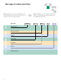
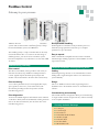
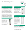
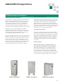
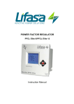
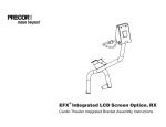
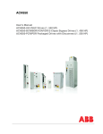
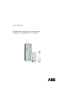
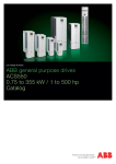
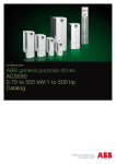
ABB low voltage drives
ACS550, 0.75 - 550 Hp
Technical Catalog
Two ways to select your drive
Choice 1: Simply contact your local ABB drives sales
office and let them know what you want. Use page 5 as
a reference section for more information.
Type code
1
2
3
4
5
6
7
2
Product series
Ratings and Types
Voltages
Construction
Dimension
Options
External Options
OR
ACS550
-
Choice 2: Build up your own ordering code using the
simple 7-step approach below and then contact your
local ABB Drive Sales Office.
U1
-
03A3
-
4
+
B055
Contents
ABB Standard Drive, ACS550
ABB Standard Base Drive...........................................................................................................................4
Ratings, Types and Voltages..........................................................................................................6
Construction....................................................................................................................................7
Advanced Control Panel.................................................................................................................7
Options...........................................................................................................................................8
Control Interfaces
How to select options..........................................................................................................8
Panel Mounting Kit..............................................................................................................8
DriveWindow Light 2...........................................................................................................8
Plug-in Options
Relay Output Extension Option Module..............................................................................9
Pulse Encoder Interface......................................................................................................9
Plug-in Fieldbus Module.....................................................................................................9
115/230V Digital Interface...................................................................................................9
External Options
Brake Units and Choppers................................................................................................10
Technical Data.............................................................................................................................. 11
Cooling.........................................................................................................................................12
Input Cable and Fuse Connections..............................................................................................13
Technical Specification.................................................................................................................14
Control Connections.....................................................................................................................15
ABB Packaged Drives...............................................................................................................................16
Ratings, Types and Voltages........................................................................................................17
Dimensions...................................................................................................................................19
3
ABB ACS550 Standard Drive
What is the ACS550 Customer Value?
■ Reduced commissioning and installation costs
■ Many assistants including Start-up, Drive Optimizer, Real-time Clock, Diagnostics, Maintenance, Serial and PID.
■ Two soft-keys that change according to the operator panel state
■ Field upgradeable firmware
■ Easy connection of cables
■ New conduit box is suitable for US and Europe
■ Built-in brake chopper (10Hp, 230V / 15Hp, 480V and 600 V)
■ Optional plug-in fieldbus modules
■ Reduced size and weight with Patented Swinging Choke (R1-R6) - equivalent to a 5% Line Impedance
■ 3% Impedance AC Line Reactor (R8) ■ Removable operator panel
■ Only Class T fuses required for high speed short circuit protection
■ NEMA 12 enclosure does not require derating
■ Smaller physical size of internal option slots
■ FlashDrop programming (unpowered drive)
Where can it be used?
The ABB ACS550 standard drive can be used in a wide
range of industries. Typical applications include pump,
fan and constant torque use, such as conveyors. The ABB
ACS550 standard drive is ideal for those situations where
there is a need for simplicity to install, commission and use
and where customizing or special product engineering is not
required.
ABB ACS550 standard drive promises
■Quick delivery
■Easy installation
■Trouble-free start-up
■Intuitive operation
Highlights:
■Advanced control panel permitting intuitive operation
■Patented swinging choke for superior harmonic
reduction (R1-R4) and AC line reactor (R5-R8)
■ Reduced energy costs without power factor ■Sensorless vector control
penalties and correction capacitors
■Integral EMC filter as standard
■ Patented swinging choke provides substantially ■Built-in Modbus RTU and numerous internally
reduced harmonics, more inductance to the correct mountable fieldbus adapters
load and higher power factor
■FlashDrop
■ Up to 25% less THD v. traditional DC choke
■ Coated boards for harsh environments
■ Daily timer controls for time-of-day backoff e.g. ■UL, cUL, C-Tick and Gost-R approved
start/stop process changes
■Built-in brake chopper (10Hp, 230V / 15Hp, 480V and 600 V)
■ Reduced Drive-Motor system failures and costs
■Many assistants including Start-up, Drive Optimizer, ■ Preventative "Maintenance Assistant" annunciation Real-time Clock, Diagnostics, Maintenance, Serial feature schedules Drive-Motor system maintenance and PID
■Seismic Certification to ICC AC-156 Criteria
The ABB ACS550 AC drive combines a sophisticated microprocessor with an advanced IGBT power switching
technology to deliver V/Hz, Closed Loop Flux Vector and
Sensorless Vector control of AC motors. Its intuitive control
panel offers numerous benefits making it the most userfriendly panel in the drives industry. The extensive library of
pre-programmed application macros maximizes convenience
and minimizes start-up time. This drive can handle the most
demanding industrial applications in an efficient, dependable
and economic manner
4
What are the ACS550's Main Features and Benefits Supporting Customer Value?
Feature
Note
Benefit
Advanced Control Panel
Two soft-keys change according to the state of the panel
Built-in "Help" button
Real-time clock, allows timed tracing of faults and setting of parameters at various
times of day
Changed parameter menu
Easy commissioning
Fast set-up
Easier configuration
Rapid fault diagnostics
Quick access to recent parameter changes
Brake Chopper
Built-in up to 15 Hp (480 and 600V) and up to 10 Hp (240V)
Reduced installation cost
Chokes
5% equivalent impedance swinging choke-matches the right inductance to the
right load, suppressing and reducing harmonics (R1-R4), 3% impedance AC line
reactor (R5-R8)
Reduces Total Harmonic Distortion (THD) emissions up to 25%
Connectivity
Simple to install:
Easy connection of cables
Easy connection of external fieldbus systems through multiple I/Os and plug-in
options
Reduced installation time
Secure cable connections
Assistants (v3.11a+)
Diagnostic assistant activated when fault occurs
Maintenance assistant monitors running hours or motor rotation
Start-up assistant guides user through all essential settings without going to
parameter list and offers option for parameter backup automatically
PID Controller assistant guides user set-up without going to parameter list
Real-time clock assistant helps user adjust time and date functions
Serial communications assistant provides a convenient way to set-up fieldbus
connections
Drive optimizer permits user to choose drive set-up for low noise, drive & motor
efficiency or motor control accuracy
Quick fault diagnostics
Takes care of drive preventative maintenance
Easy set-up of parameters
Simplifies closed loop process control adjustment
Allows quick adjustment of time and date
Provides easy set-up of fieldbus connectivity
Quickly tailors drive to application
Built-in EMC
Built-in category C2 (1st environment) filter
No need for external filtering
Sensorless vector control
Improve motor control performance
Enables wider range of applications
Switching frequency control
Permits the highest possible switching frequency based on operating and ambient
conditions
Considerable motor noise reduction and improved
efficiency
Flashdrop
Faster and easier drive set-up and programming
New fast, safe and trouble free method to download
parameters available without powering the drive
- patented
Coated boards
Longer lifetime in hostile environments. Reduced servicing requirements
Protections against moisture and hostile particles
as standard
Flange Mounting Kits
Allows mounting the drive with the heatsink external to a 3rd party enclosure
- frame size R1-R6.
Reduces heat and enclosure size
5
Ratings, Types and Voltages
Type code
This is the unique reference number that clearly indentifies
the drive by mounting configuration, power rating and
voltage. Once you have selected the type code, the frame size
can be used to determine the drives dimensions, shown on
the next page.
Voltages
The ACS550 is available in three voltage ranges:
2 = 208 - 240V
4 = 380 - 480V
6 = 500 - 600V
Notes
1 I2N: continuous base current with 110% overload for
1 minute / 10 minutes.
2 I2hd: continuous base current with 150% overload for
1 minute / 10 minutes.
3 180% Ihd continuous base current available for 2 seconds
/ 1 minute.
4 The rated current of the ACS550 must be greater than
or equal to the rated motor current to achieve the rated
motor power given in the table.
5 All -U1 models come with a conduit box and advanced
control panel as standard.
6 Horsepower is based on NEMA motor ratings for most
4-pole motors (1800 rpm). Check motor nameplate current for compatibility.
7 All 230V product can be operated on 230V single-phase
power, using a de-rate of the output current of 50%.
8 All -U2 models come standard with US conduit openings, top entry / top exit, common mode filter for drives
larger than 200 HP, fused disconnect and extended enclosure with advanced control panel.
6
Nominal Ratings
Type Code
UL Type 1
NEMA 1 (5,8)
ACS550-U1-04A6-2
ACS550-U1-06A6-2
ACS550-U1-07A5-2
ACS550-U1-012A-2
ACS550-U1-017A-2
ACS550-U1-024A-2
ACS550-U1-031A-2
ACS550-U1-046A-2
ACS550-U1-059A-2
ACS550-U1-075A-2
ACS550-U1-088A-2
ACS550-U1-114A-2
ACS550-U1-143A-2
ACS550-U1-178A-2
ACS550-U1-221A-2
ACS550-U1-248A-2
ACS550-U1-03A3-4
ACS550-U1-04A1-4
ACS550-U1-06A9-4
ACS550-U1-08A8-4
ACS550-U1-012A-4
ACS550-U1-015A-4
ACS550-U1-023A-4
ACS550-U1-031A-4
ACS550-U1-038A-4
ACS550-U1-045A-4
ACS550-U1-059A-4
ACS550-U1-072A-4
ACS550-U1-078A-4
ACS550-U1-097A-4
ACS550-U1-125A-4
ACS550-U1-157A-4
ACS550-U1-180A-4
ACS550-U1-246A-4
ACS550-U2-316A-4
ACS550-U2-368A-4
ACS550-U2-414A-4
ACS550-U2-486A-4
ACS550-U2-526A-4
ACS550-U2-602A-4
ACS550-U2-645A-4
ACS550-U1-02A7-6
ACS550-U1-03A9-6
ACS550-U1-06A1-6
ACS550-U1-09A0-6
ACS550-U1-011A-6
ACS550-U1-017A-6
ACS550-U1-022A-6
ACS550-U1-027A-6
ACS550-U1-032A-6
ACS550-U1-041A-6
ACS550-U1-052A-6
ACS550-U1-062A-6
ACS550-U1-077A-6
ACS550-U1-099A-6
ACS550-U1-125A-6
ACS550-U1-144A-6
Normal Duty (CT)
(110% I2N)
I 2N
A (1,7)
4.6
6.6
7.5
11.8
16.7
24.2
30.8
46.2
59.4
74.8
88
114
143
178
221
248
3.3
4.1
6.9
8.8
11.9
15.4
23
31
38
44
59
72
77
96
124
157
180
245
316
368
414
486
526
602
645
2.7
3.9
6.1
9
11
17
22
27
32
41
52
62
77
99
125
144
PN
HP (4,6)
1.0
1.5
2.0
3.0
5.0
7.5
10
15
20
25
30
40
50
60
75
100
1.5
2
3
5
7.5
10
15
20
25
30
40
50
60
75
100
125
150
200
250
300
350
400
450
500
550
2
3
5
7.5
10
15
20
25
30
40
50
60
75
100
125
150
Heavy Duty (CT)
(150% I2hd)
I 2hd
A (2,3,7)
3.5
4.6
6.6
7.5
11.8
16.7
24.2
30.8
46.2
59.4
74.8
88
114
150
178
192
2.4
3.3
5.4
6.9
8.8
11.9
15.4
23
31
38
44
59
65
77
96
124
156
192
240
302
368
414
477
515
590
2.4
2.7
3.9
6.1
9
11
17
22
27
32
41
52
62
77
99
125
P hd
HP (4,6)
0.75
1.0
1.5
2
3
5
7.5
10
15
20
25
30
40
50
60
75
1
1.5
2
3
5
7.5
10
15
20
25
30
40
50
60
75
100
125
150
200
250
300
350
400
450
500
1.5
2.0
3.0
5.0
7.5
10
15
20
25
30
40
50
60
75
100
125
Frame
Size
R1
R1
R1
R1
R1
R2
R2
R3
R3
R4
R4
R4
R6
R6
R6
R6
R1
R1
R1
R1
R1
R2
R2
R3
R3
R3
R4
R4
R4
R4
R5
R6
R6
R6
R8
R8
R8
R8
R8
R8
R8
R2
R2
R2
R2
R2
R2
R3
R3
R4
R4
R4
R4
R6
R6
R6
R6
Construction
“U1” within the type code indicates the drive mounting configuration. U1 models
are wall-mounted, while "U2" models are free-standing with an extended enclosure
and fused disconnect. Choose the correct one for your needs from the table below:
U1
U2
■Wall mounted, frame size R1-R6
■0.75 - 200 HP
■UL Type 1 (IP21) NEMA 1 or
UL Type 12 (IP54) NEMA 12
■Built-in EMC filter
■Standard software
■Built-in Modbus RTU interface
■Cable connection box
■Brake chopper in frame sizes R1-R2
■Advanced control panel
■Swinging choke (Frames R1-R6)
■Free standing, frame size R8
■250 - 550Hp
■UL Type 1 (IP21) NEMA 1
■Standard software
■Built-in Modbus RTU interface
■Free-standing with extended
enclosure and fused disconnect
■Advanced control panel
■AC Reactor (Frame R8)
Advanced Control Panel
For easy drive programming, a detachable, multilingual
alphanumeric advanced control panel is delivered as standard. The control panel has various assistants and built-in
help functions to guide the user. It includes a real time
clock, which can be used during fault logging and in
Name
Function
Start
Initiates operation of drive
Stop
Ceases operation of drive
Up
Down
Loc/Rem
HELP
Changes parameters and their value/ increases reference
Changes parameters and their value/ decreases reference
Changes drive state from local control to
remote control (I/O or other external source)
Built-in “Help” button
controlling the drive, such as start/stop and maintenance
reminders. The control panel can be used for copying parameters for back up or for downloading to another drive. A
large graphical display and soft keys make it extremely easy
to navigate.
Local/Remote indication
Motor rotation indicator
Speed reference
Actual value 1, Actual motor speed (selectable)
Actual value 2, Output current (selectable)
Actual value 3, Process value (selectable)
Soft key 2 function
Real time clock
Soft key 1 function
Soft key 1 Function changes according to state of panel
Soft key 2 Function changes according to state of panel
7
Options
Control Interfaces
How to select options
DriveWindow Light 2 (3AFE64532871)
The options shown below are available for use with the
ACS550. Each item has a 4-digit option code, which is
shown in the table below. This code is added to the end of
the type code above using a '+'. Ordering options using the
plus option code provides a factory installed option, while
using the field kit code provides a field installable kit (-KIT).
Available options
Plus Option
Code
Description
Field Kit Code
Protection class
+B055
UL Type 12 (IP54) NEMA 12
Slot 1 Options
+L511
Relay Output Extension
+L502
Pulse Encoder Interface
Slot 2 Options
+L512
+K451
+K454
+K462
+K466 +K457 +K467
OREL-01-KIT
OTAC-01-KIT
115/230V Digital Input InterfaceOHDI-01-KIT
DeviceNet
RDNA-01-KIT
Profibus-DP
RPBA-01-KIT
ControlNet
RCNA-01-KIT
EtherNet/IP and Modbus/TCP
RETA-01-KIT
CANopen
RCAN-01-KIT
PROFINET and Modbus/TCP
RETA-02-KIT
NOTE:
- Only one option can be installed in each option slot.
- Embedded Modbus RTU
Panel Mounting Kit (OPMP-01)
The panel mounting kit, OPMP-01, enables mounting of control
panels on cabinet doors. This kit includes a 10 ft (3 m) extension
cable, a gasket, mounting screws and a mounting template.
ACS-CP-EXT: permits permanent mounting of panel to external surface of NEMA 1 or NEMA 12 enclosures.
ACS-CP-EXT-IP66: permits permanent mounting of panel to
external surface of NEMA 4X enclosures.
8
DriveWindow Light 2 is a PC software used for rapid
commissioning, operating and programming of drives. It has
features for programming, monitoring, troubleshooting and
maintenance.
It is also a set-up and control tool which is Win98, WinNT,
Win2000 and WinXP compatible. DriveWindow Light 2 operates both off- and on-line. No
additional PC hardware is required. It uses the PC’s
RS-232 port. It is also compatible with drive types ACS350,
ACS800, DCS400 and DCS800.
DriveWindow Light 2 features
nGraphical start-up wizards
nOff- and on-line viewing and changing of drive
parameters
nBackup and restore parameters. In a fault situation, the
parameters can be reloaded resulting in time savings
nGraphical monitoring of actual signal values
nI/O mapping table
nControl of the drive
DrivePM
DrivePM (Parameter Manager) is a software tool designed to
create, edit and copy parameter sets included with a FlashDrop. For each parameter, and parameter group, the user
can change the default or hide the parameter or entire group.
FlashDrop does not require the drive to have power applied.
FlashDrop is also compatible with the ACS150 and ACS350.
FlashDrop MFDT-01
FlashDrop is a powerful palm-sized tool for fast and easy
parameter selecting and setting. This tool can be used to
download parameters to a drive in less than three seconds.
Using this tool, it is possible to hide
selected parameters to protect the
machine. Only parameters needed in
the application are shown. FlashDrop
does not require the drive to be powered. The MFDT-01 includes Drive PM
(Drive Parameter Manager) software
FlashDrop
tool to create, edit and copy parameter sets. (MFDT-01)
Options
Plug-in Options
Relay Output Extension Module (+L511)
This plug-in option offers three additional relay
outputs. They can be used to actuate motor starters
for pumps using a lead-lag alternation scheme with
the built-in Pump-Fan Macro. All relays can be programmed to on/off by using the advanced control
panel’s clock. Alternatively, fieldbus adapters can be
used to control any external components in the system.
Pulse Encoder Interface (+L502)
The Pulse Encoder Interface module offers a differential or single ended interface for a digital pulse encoder
connection. The module is capable of operating from
either a 15 or 24 VDC signal with a maximum frequency of 200kHz.
FlashDrop
probe port
Analog I/O
Digital
inputs
Relay outputs
115/230V Digital Input Interface (+L512)
The 115/230V Digital Input Interface module offers
six (6) 115V or three (3) 230V rated relays mounted on
a common board used to drive DI1 through DI6 of the
ACS550. The 115/230V must be provided by the user.
The module cannot be used in conjunction with any
fieldbus module as it occupies the same option slot.
Built-in Modbus RTU
using RS 485
Plug-in Feldbus Modules
The plug-in fieldbus options bring connectivity to major automation systems. A single twisted pair avoids
large amounts of conventional cabling, thereby reducing cost and increasing system reliability.
The ACS550 supports the following fieldbus options:
nCANopen
nControlNet™
nDeviceNet™
nEmbedded Modbus ® RTU
nEtherNet/IP™ Modbus/TCP ®
nProfibus-DP ®
nPROFINET IO ®
NOTE:
- Only one option can be installed in each option slot.
9
Options
External Options
Brake Units and Choppers
Frame sizes R1 to R2 are delivered with integrated brake
choppers as standard. Other units can use an external brake
chopper and resistor. For more information, please refer
to the ABB Low Voltage Drives PowerOhm Resistors Price List.
(LVD-PNPL02U-EN).
Flange Mounting Kits
Flange Mounting Kits for the ACS550 drives allow mounting
of the drive with the heatsink external to a 3rd party
enclosure. Use of the flange kit requires removal of the drive
cover, reducing protection to IP00. The flange kit can be used
with 3rd party UL Type 1 & 12 (NEMA 1 & 12) enclosures.
R5 and R6 kits provide NEMA 1 protection only.
Flange Mounting Kits
10
Frame Size
Field Kit Code
R1
FMK-A-R1
R2
FMK-A-R2
R3
FMK-A-R3
R4
FMK-A-R4
R5
AC8-FLNGMT-R5
R6
AC8-FLNGMT-R6
Technical Data
Cooling
Cooling Air Flow 208 - 240V Units
Type Code
Frame
Size
W
BTU/Hr
Cooling Air Flow 380 - 480V Units
m3/h
ft3/min
Type Code
Frame
Size
W
BTU/Hr
m3/h
ft3/min
-04A6-2
R1
55
189
44
26
-03A3-4
R1
40
137
44
26
-06A6-2
R1
73
249
44
26
-04A1-4
R1
52
178
44
26
-07A5-2
R1
81
276
44
26
-06A9-4
R1
97
331
44
26
-012A-2
R1
118
404
44
26
-08A8-4
R1
127
434
44
26
-017A-2
R1
161
551
44
26
-012A-4
R1
172
587
44
26
-024A-2
R2
227
776
88
52
-015A-4
R2
232
792
88
52
-031A-2
R2
285
973
88
52
-023A-4
R2
337
1151
88
52
-046A-2
R3
420
1434
134
79
-031A-4
R3
457
1561
134
79
-059A-2
R3
536
1829
134
79
-038A-4
R3
562
1919
134
79
-075A-2
R4
671
2290
280
165
-045A-4
R3
667
2278
134
79
-088A-2
R4
786
2685
280
165
-059A-4
R4
907
3098
280
165
-114A-2
R4
1014
3463
280
165
-072A-4
R4
1120
3825
280
165
-143A-2
R6
1268
4331
405
238
-078A-4
R4
1300
4300
280
165
-178A-2
R6
1575
5379
405
238
-097A-4
R4
1440
4918
280
165
-221A-2
R6
1952
6666
405
238
-125A-4
R5
1940
6625
350
205
-248A-2
R6
2189
7474
405
238
Cooling Air Flow 500 - 600V Units
Type Code
Frame
Size
W
BTU/Hr
m3/h
ft3/min
-02A7-6
R2
46
157
88
52
-03A9-6
R2
68
232
88
52
-06A1-6
R2
124
423
88
52
-09A0-6
R2
170
581
88
52
-011A-6
R2
232
792
88
52
-017A-6
R2
337
1150
88
52
-022A-6
R3
457
1560
134
79
-027A-6
R3
562
1918
134
79
-032A-6
R4
667
2276
280
165
-041A-6
R4
907
3096
280
165
-052A-6
R4
1120
3820
280
165
-062A-6
R4
1295
4420
280
165
-077A-6
R6
1504
5136
405
238
-099A-6
R6
1821
6219
405
238
-157A-4
R6
2310
7889
405
238
-180A-4
R6
2810
9897
405
238
-246A-4
R6
3850
13148
540
318
-316A-4
R8
4550
15539
1220
718
-368A-4
R8
6850
23394
1220
718
-414A-4
R8
7400
25000
1220
718
-486A-4
R8
7850
26809
1220
718
-526A-4
R8
7600
25955
1220
718
-602A-4
R8
8100
27663
1220
718
-645A-4
R8
9100
31078
1220
718
ACS550 are configured with cooling air fans. The cooling
air must be free from corrosive materials with a maximum
ambient temperature of 40oC (50oC with derating).
Free space requirements
Enclosure Type
Space
above
mm / in
Space
below
mm / in
Space on
left and right
mm / in
200 / 7.9
200 / 7.9
0
200 / 7.9
0
0
-125A-6
R6
2442
8339
405
238
U1 - Wall Mount
-144A-6
R6
2813
9607
405
238
U2 - Floor Mount
11
Technical Data
Fuse connections
Standard fuses can be used with ABB standard drives. For
fuse connections see table below.
Recommended input protection fuses
12
Mains Fuses
Type Code
Frame
Size
Input Current
A
IEC269 gG (A)
UL Class T (A)
-04A6-2
-06A6-2
-07A5-2
-012A-2
-017A-2
-024A-2
-031A-2
-046A-2
-059A-2
-075A-2
-088A-2
-114A-2
-143A-2
-178A-2
-221A-2
-248A-2
-03A3-4
-04A1-4
-06A9-4
-08A8-4
-012A-4
-015A-4
-023A-4
-031A-4
-038A-4
-045A-4
-059A-4
-072A-4
-078A-4
-097A-4
-125A-4
-157A-4
-180A-4
-246A-4
-316A-4
-368A-4
-414A-4
-486A-4
-526A-4
-602A-4
-645A-4
-02A7-6
-03A9-6
-06A1-6
-09A0-6
-011A-6
-017A-6
-022A-6
-027A-6
-032A-6
-041A-6
-052A-6
-062A-6
-077A-6
-099A-6
-125A-6
-144A-6
R1
R1
R1
R1
R1
R2
R2
R3
R3
R4
R4
R4
R6
R6
R6
R6
R1
R1
R1
R1
R1
R2
R2
R3
R3
R3
R4
R4
R4
R4
R5
R6
R6
R6
R8
R8
R8
R8
R8
R8
R8
R2
R2
R2
R2
R2
R2
R3
R3
R4
R4
R4
R4
R6
R6
R6
R6
4.6
6.6
7.5
11.8
16.7
24.2
30.8
46.2
59.4
74.8
88.0
114.0
143.0
178.0
221.0
248.0
3.3
4.1
6.9
8.8
11.9
15.4
23.0
31.0
38.0
44.0
59.0
72.0
77.0
96.0
124.0
157.0
180.0
245.0
316.0
368.0
414.0
486.0
526.0
602.0
645.0
2.7
3.9
6.1
9.0
11.0
17.0
22.0
27.0
32.0
41.0
52.0
62.0
77.0
99.0
125.0
144.0
10
10
10
16
25
25
40
63
63
80
100
125
200
250
315
315
10
10
10
10
16
16
25
35
50
50
63
80
80
125
160
200
250
250
400
400
500
500
630
630
800
10
10
10
16
16
25
25
35
35
50
60
80
80
125
160
200
10
10
10
15
25
30
40
60
80
100
110
150
200
250
300
350
10
10
10
15
15
20
30
40
50
60
80
90
100
125
175
200
250
250
400
400
500
500
630
630
800
10
10
10
15
15
25
25
40
40
50
60
80
100
150
175
200
Technical Specification
Input power connection
Voltage and power range
3-phase, 208 to 240 V, +10/-15%, 0.75 - 100Hp
3-phase, 380 to 480 V, +10/-15%, 1 - 550Hp
3-phase, 500 to 600V, +10/-15%, 1.5 - 150Hp
Frequency
48 to 63 Hz
Power factor
0.98
Motor connection
Voltage
3-phase, from 0 to USUPPLY
Frequency
0 to 500 Hz
Continuous loading
capability
Rated output current I2N
(constant torque at a max ambient temperature of 400c)
Programmable control connections
Two analog inputs
Voltage signal
Current signal
Potentiometer reference value
Maximum delay
Resolution Accuracy
0 (2) to 10 V, Rin > 312 kΩ single-ended
0 (4) to 20 mA, Rin = 100 Ω single-ended
10 V ±2% max. 10 mA, R < 10 kΩ
12...32 ms
0.1%
±1%
Two analog outputs
Accuracy
0 (4) to 20 mA, load < 500 Ω
±3%
Auxiliary voltage
24 V DC ±10%, max. 250 mA
Six digital inputs
Input impedance
Maximum delay
12 V... 24 V DC with internal or external
supply, PNP and NPN
2.4 kΩ
5 ms ± 1ms
Three relay outputs
Maximum switching voltage
Maximum switching current
Maximum continuous current
250 V AC/30 V DC
6 A/30 V DC; 1500 V A/230 V AC
2 A rms
Serial communication
RS 485
Built-in Modbus RTU protocol
Overload capacity
a max. ambient tempera(at
ture of 400c)
At normal use 1.1 x I2N for 1 minute
every 10 minutes
At heavy-duty use 1.5 x I2hd for 1 minute
every 10 minutes
Always 1.8 x I2hd for 2 seconds every
60 seconds
Switching frequency
Standard Selectable
Default 4 kHz
0.75 - 150Hp 1 kHz, 4 kHz, 8 kHz, 12 kHz
up to 550Hp
1 kHz, 4 kHz
Acceleration time
0.1 to 1800 s
Product compliance
Deceleration time
0.1 to 1800 s
240V products:
UL, cUL, CSA, CE, C-TICK, and GOST-R approvals
480V products:
UL, cUL, CSA, CE, C-TICK, and GOST-R approvals
600V products:
UL, cUL, CSA, C-TICK, and GOST-R approvals
Environmental limits
Ambient temperature
-15 to 40oC o
40 to 50 C
o
No frost
C (5 to 104oF)
-15
to 40allowed
o
o
f40
4
kHz,
derating
please
C
(104
to 122
F) contact supplier
to
50
switch
Altitude
Output
current
Altitude
Output
current
No frost allowed
EMC Directive 89/336/EEC with supplements
Rated
current
at 0 toto1000
PN available
and I2 derated
90% m (3300 ft)
fswitch 4 kHz,
reduced by 1% per 100 m over 1000 m (3300 ft) to 2000current
m (6600
ft)
Rated
available
at 0 to 1000 m (3300 ft)
Quality assurance system ISO 9001 and Environmental system ISO 14001
Relative humidity
Protection class
Relative
humidity
Enclosure
colour
Protection
class
Contamination
levels
lower than
(without
condensation)
reduced
by95%
1% per
100 m
over 1000 m (3300 ft) to
ft)
UL2000
Typem1 (6600
or 12 (NEMA
1 or NEMA 12)
lower
than 95%
(without
NCS 1502-Y,
RAL
9002, condensation)
PMS 420 C
Transportation
Enclosure
color
Contamination
levels
Storage
Transportation
Operation
Storage
UL
1 or 12
(NEMA
1 or NEMA 12)
No Type
conductive
dust
allowed
IEC60721-3-1,
class
1C3PMS
(chemical
NCS
1502-Y, RAL
9002,
420 Cgases),
Class
1S3 (solid particles)
IEC
721-3-3
IEC60721-3-2,
Classallowed
2C3 (chemical gases),
No
conductive dust
Class 1C2
2S3 (solid
particles)
Class
(chemical
gases),
IEC60721-3-3,
3C3 (chemical gases),
Class
1S2 (solidClass
particles)
Class 2C2
3S3 (solid
particles)
Class
(chemical
gases),
Operation
Class 2S2 (solid particles)
Class 3C2 (chemical gases),
Class 3S2 (solid particles)
Motor Control
Speed Control
Open Loop
Closed Loop
Open Loop
Closed Loop
20% of motor nominal slip
0.1% of motor nominal speed
< 1% s with 100% torque step
0.5% s with 100% torque step
Motor Control
Open Loop
Closed Loop
Open Loop
Closed Loop
<10ms with nominal torque
<10ms with nominal torque
±5% with nominal torque
±2% with nominal torque
Low Voltage Directive 73/23/EEC with supplements
Machinery Directive 98/37/EC
Seismic Certification to ICC AC-156
EMC
according
to EN61800-3
Mains
connection
1st environment restricted distribution for frame sizes R3, R4 with 75 m motor
cables and for frame sizes R1, R2, R5, R6 with 100 m motor cables.
2nd environment unrestricted distribution for frame sizes R1 - R4 with 300 m
cable and for frame sizes R5 - R8 with 100 m motor cables as standard.
These cable lengths are for EMC purposes only. For long motor cable
lengths, external EMC filters are available on request.
Mains connection
EMC standards in general
EN 61800-3/A11 (2000),
product standard
EN 61800-3 (2004),
product standard
EN 55011, product family
standard for industrial,
scientific and medical
(ISM) equipment
1st Environment,
unrestricted distribution
Category C1
Group 1
Class B
1st Environment,
restricted distribution
Category C2
Group 1
Class A
2nd Environment,
unrestricted distribution
Category C3
Group 2
Class A
2nd Environment,
restricted distribution
Category C4
Not Applicable
13
Control Connections
These connections are shown as examples only. Please refer to the ACS550 User’s Manual (3AUA0000001609) for more detailed
information.
R < 10 kohm
14
R < 10 kohm
Fieldbus Control
Gateway to your process
ABB AC drives have the connectivity to major automation
systems. This is achieved with a dedicated gateway concept
between the fieldbus systems and ABB drives.
The fieldbus gateway is a snap-on module that can be easily
mounted inside the drive. As a result of the wide range of
fieldbus gateways, your choice for an automation system
becomes independent of your decision to use first-class ABB
AC drives.
Manufacturing Flexibility
Drive control
The drive Control Word (16 bit) provides a wide variety of
functions from Start, Stop and Reset to Ramp Generator
control. Typical setpoint values like Speed, Torque and
Position can be transmitted to the drive with 15 bit accuracy.
Drive monitoring
A set of drive parameters and/or actual signals, like torque,
speed, position, current etc., can be selected for cyclic
data transfer providing fast data for operators and the
manufacturing process.
Drive diagnostics
Accurate and reliable diagnostic information can be obtained
via the drive Alarm, Limit and Fault Words reducing the down
time of the drive and therefore, also the down time of the
manufacturing process.
Drive parameter handling
Total integration of the drives in the production process is
achieved by single parameter read/write up to complete
parameter set-up or download.
Easy to expand
Serial communication simplifies the latest trend of modular
machine design enabling expansion of the installation at a later
stage with low effort.
Reduced Installation and Engineering Effort
Cabling
Substituting the large amount of conventional Drive Control
cabling with a single twisted pair reduces costs and increases
system reliability.
Design
The use of Fieldbus Control reduces engineering time at
installation due to the modular structure of the hardware and
software.
Commissioning and assembly
The modular machine configuration allows pre-commissioning
of single machine sections and provides easy and fast assembly
of the complete installation.
Currently Available Gateways
■CANopen
■ControlNet™
■DeviceNet™
■Embedded Modbus® RTU
■Modbus/TCP®
■EtherNet/IP™
■Profibus-DP®
■PROFINET IO®
15
ABB ACS550 Packaged Drives
ACS550 Packaged Drive
ACS550-PC and PD packaged drives combine ACS550 AC
drives with the disconnect arrangement of your choice in one
coordinated, easy to install package. Packages are available with
an input disconnect switch and fast acting, current limiting
fuses (ACS550-PD) or an input circuit breaker (ACS550-PC).
Units with a circuit breaker disconnect at and above ratings
of 30 HP at 208/240V and 75 HP at 480 & 600V are also
equipped with fast acting, drive input fuses to limit damage
to the drive and provide for the possibility of drive repair in
the unlikely event that a short circuit or ground fault should
develop within the input power structure of the drive.
Disconnects are externally operable and interlocked with the
enclosure door. The cover mounted disconnect operating
handle may be padlocked in the off position with up to three
padlocks. The multilingual, alphanumeric drive control panel
is provided on the cover of NEMA 1 and NEMA 12 enclosed
devices, and on the drive within NEMA 3R enclosed units.
Vertical Wall Mount Enclosures
NEMA 1 and NEMA 12 enclosed
ACS550-PC and PD Drives with
Disconnect through 25 HP at
208/240V and 60 HP at 480 and
600V are provided in vertical wall
mount enclosures. This unique
construction provides a minimum
footprint advantageous for use in
overcrowded electrical rooms or
mezzanines, or for direct mounting
on machines or columns. Input
and output conduit entry is at the
bottom of the enclosure.
Oversized Wall Mounting Enclosures
For NEMA 1 and NEMA 12 enclosed
ACS550-PC and PD Drives with
Disconnect from 30 to 100 HP at
208/240V, 75 to 200 HP at 480 &
600V, wall mounting enclosures
are sized to accommodate the field
addition of components that users
frequently desire to include at
these higher horsepower ratings. A
removable conduit plate is provided at
the top of the enclosure.
Free Standing Packages
From 250 HP to 550 HP at 480V,
ACS550-PC enclosures will
accommodate the field installation
of additional components. Where
additional enclosure panel space
is required, an auxiliary enclosure
section is available. A molded
case circuit breaker provides the
disconnect means function while
fast acting, current limiting drive
input fuses provide short circuit
protection. A removable conduit
mounting plate is provided at the
top of the enclosure.
NEMA 3R Enclosures
For outdoor applications, the ACS550 Drive with
Disconnect is available in NEMA 3R enclosures up to 100
HP at 208/240V and 200 HP at 480 & 600V. Construction
is sheet steel with a tough powder coat paint finish for
corrosion resistance. A 100 watt, thermostatically controlled
space heater and thermostatic control of the force ventilated
cooling system are provided as standard.
16
ABB ACS550 Packaged Drives
ACS550 Packaged Drive with Bypass
ACS550 Packaged Drive with Bypass
Externally Operated Devices
The ACS550-CC is a complete Drive with Bypass Package that
includes an ACS550 Adjustable Frequency Drive, a bypass
function that allows the motor to be run at full voltage in the
event the drive is shut down for service, a main disconnect
means and branch circuit short circuit and ground fault
protection. Complete, pre-engineered packages reduce time,
effort and the cost of installing the popular drive bypass option.
ACS550 Drive with Bypass Packages include an input circuit
breaker with a door mounted external operating handle that
is interlocked with the enclosure door and lockable in the
OFF position with up to three padlocks. The multilingual,
alphanumeric drive control panel is mounted on the door of the
enclosure. An optional drive service switch (+F267) isolates the
drive from the power source for service and provides superior
functionality to a three-contactor arrangement.
The bypass function is configured entirely of standard
industrial control components. It includes two electrically
interlocked contactors, a motor overload relay, a control power
transformer with primary and secondary fusing, and a cover
mounted DRIVE-OFF-BYPASS selector switch.
Bypass is accomplished by means of the two contactors. One is
the bypass contactor used to connect the motor directly to the
power line. The other is the output contactor that disconnects
the motor from the drive output when operating in the
bypass mode. This prevents the “back feeding” that would
occur if line voltage were applied to the drive output terminals.
The drive output contactor and the bypass contactor are
electrically interlocked to prevent simultaneous operation.
NEMA 1 Wall Mount
Drive Input Fuses Standard
Fast acting, current limiting drive input fuses are provided as
standard to limit damage and allow for possible drive repair if
a short circuit or ground fault should develop in the drive input
bridge. This is particularly pertinent for drives at the higher
ratings where it is generally more economical to repair rather
than replace the drive. The drive fuses are also intended to
provide for immediate operation of the bypass function after
such a fault.
Enclosure Options
Drive with Bypass Packages are available in NEMA 1 and
NEMA 12 enclosures through 100 HP at 208/240V, 400
HP at 480V and 150 HP at 600V. For outdoor applications,
NEMA 3R enclosed packages are available through 100
HP at 208/240V and 200 HP at 480 & 600V. NEMA 3R
enclosures are sheet steel construction with a tough powder
coat paint finish for corrosion resistance and include a 100
watt, thermostatically controlled space heater and thermostatic
control of the force ventilated cooling system as standard.
NEMA 1 Floor Mount
NEMA 3R Floor Mount
17
Ratings, Types and Voltages
600V
480V
208/240 V
System
Frame
Base Drive Type Code
Voltage
Size
ACS550-XX-04A6-2
ACS550-XX-06A6-2
ACS550-XX-07A5-2
ACS550-XX-012A-4
ACS550-XX-017-A2
ACS550-XX-024A-2
ACS550-XX-031A-2
ACS550-XX-046A-2
ACS550-XX-059A-2
ACS550-XX-075A-2
ACS550-XX-088A-2
ACS550-XX-114A-2
ACS550-XX-143A-2
ACS550-XX-178A-2
ACS550-XX-221A-2
ACS550-XX-248A-2
ACS550-XX-03A3-4
ACS550-XX-04A1-4
ACS550-XX-06A9-4
ACS550-XX-08A8-4
ACS550-XX-012A-4
ACS550-XX-015A-4
ACS550-XX-023A-4
ACS550-XX-031A-4
ACS550-XX-038A-4
ACS550-XX-045A-4
ACS550-XX-059A-4
ACS550-XX-072A-4
ACS550-XX-078A-4
ACS550-XX-097A-4
ACS550-XX-125A-4
ACS550-XX-157A-4
ACS550-XX-180A-4
ACS550-XX-246A-4
ACS550-XX-316A-4
ACS550-XX-368A-4
ACS550-XX-414A-4
ACS550-XX-486A-4
ACS550-XX-526A-4
ACS550-XX-602A-4
ACS550-XX-645A-4
ACS550-XX-02A7-6
ACS550-XX-03A9-6
ACS550-XX-06A1-6
ACS550-XX-09A0-6
ACS550-XX-011A-6
ACS550-XX-017A-6
ACS550-XX-022A-6
ACS550-XX-027A-6
ACS550-XX-032A-6
ACS550-XX-041A-6
ACS550-XX-052A-6
ACS550-XX-062A-6
ACS550-XX-077A-6
ACS550-XX-099A-6
ACS550-XX-125A-6
ACS550-XX-144A-6
R1
R1
R1
R1
R1
R2
R2
R3
R3
R4
R4
R4
R6
R6
R6
R6
R1
R1
R1
R1
R1
R2
R2
R3
R3
R3
R4
R4
R4
R4
R5
R6
R6
R6
R8
R8
R8
R8
R8
R8
R8
R2
R2
R2
R2
R2
R2
R3
R3
R4
R4
R4
R4
R6
R6
R6
R6
Nominal Ratings
Normal
Heavy Duty
Duty
I2N
A
PN
HP
I2hd
A
Phd
HP
4.6
6.6
7.5
11.8
16.7
24.2
30.8
46.2
59.4
74.8
88
114
143
178
221
248
3.3
4.1
6.9
8.8
11.9
15.4
23
31
38
44
59
72
77
96
124
157
180
245
316
368
414
486
526
602
645
2.7
3.9
6.1
9
11
17
22
27
32
41
52
62
77
99
125
144
1
1.5
2
3
5
7.5
10
15
20
25
30
40
50
60
75
100
1.5
2
3
5
7.5
10
15
20
25
30
40
50
60
75
100
125
150
200
250
300
350
400
450
500
550
2
3
5
7.5
10
15
20
25
30
40
50
60
75
100
125
150
3.5
4.6
6.6
7.5
11.8
16.7
24.2
30.8
46.2
59.4
74.8
88
114
150
178
192
2.4
3.3
5.4
6.9
8.8
11.9
15.4
23
31
38
44
59
65
77
96
124
156
192
240
302
368
414
477
515
590
2.4
2.7
3.9
6.1
9
11
17
22
27
32
41
52
62
77
99
125
0.75
1
1.5
2
3
5
7.5
10
15
20
25
30
40
50
60
75
1
1.5
2
3
5
7.5
10
15
20
25
30
40
50
60
75
100
125
150
200
250
300
350
400
450
500
1.5
2
3
5
7.5
10
15
20
25
30
40
50
60
75
100
125
Notes:
xx = contruction designations:
U1 = Base Drive - Wall mount
U2 = Base Drive - Floor mount
Base
Base
Input
Input
Bypass
Bypass
Bypass
Drive
Drive
Disconnect Disconnect
NEMA 1 NEMA 12 NEMA 3R
NEMA 1 NEMA 12
NEMA 1
NEMA 12
Dim Ref Dim Ref Dim Ref
Dim Ref Dim Ref
Dim Ref
Dim Ref
CX1
CX12
CX3R
UX1
UX12
PX1
PX12
1
1
1
1
1
2
2
3
3
4
4
4
6
6
6
6
1
1
1
1
1
2
2
3
3
3
4
4
4
4
5
6
6
6
8
8
8
8
8
8
8
2
2
2
2
2
2
3
3
4
4
4
4
6
6
6
6
1
1
1
1
1
2
2
3
3
4
4
4
6
6
6
6
1
1
1
1
1
2
2
3
3
3
4
4
4
4
5
6
6
6
1
1
1
1
1
3
3
4
4
6
9
9
10
10
11
11
1
1
1
1
1
2
2
4
4
4
5
5
5
6
7
10
10
11
12
13
13
13
1
1
1
1
1
3
3
5
5
6
7
7
10
10
10
10
1
1
1
1
1
2
2
4
4
5
6
6
6
7
8
9
9
10
11
12
12
12
1
1
1
1
1
2
2
3
3
4
5
5
7
7
8
8
1
1
1
1
1
2
2
3
3
3
4
4
4
5
6
7
7
8
1
1
1
1
1
2
2
3
3
4
5
5
6
6
6
6
1
1
1
1
1
2
2
3
3
3
4
4
4
5
5
6
6
6
8
8
8
8
2
2
2
2
2
2
3
3
4
4
4
4
6
6
6
6
2
2
2
2
2
2
4
4
5
5
5
5
8
8
10
10
2
2
2
2
2
2
4
4
6
6
6
6
9
9
9
9
2
2
2
2
2
2
3
3
4
4
4
4
6
6
6
6
2
2
2
2
2
2
3
3
4
4
4
4
6
6
6
6
PD = Packaged Drive with Switch and Fuse
PC = Packaged Drive with Circuit Breaker
Input
Disconnect
NEMA 3R
Dim Ref
PX3R
1
1
1
1
1
2
2
3
3
4
5
5
6
6
6
6
1
1
1
1
1
2
2
3
3
3
4
4
4
5
5
6
6
6
8
8
8
8
8
8
8
2
2
2
2
2
2
3
3
4
4
4
4
6
6
6
6
CC = Packaged Drive with Bypass
1
1
1
1
1
2
3
3
3
4
5
5
6
6
6
6
1
1
1
1
1
2
2
3
3
3
4
4
4
5
6
6
6
6
2
2
2
2
2
2
3
3
4
4
4
4
6
6
6
6
Dimensions
ACS550-UX, NEMA 1/UL Type 1
W
D
W1
H
H
H1
W
Wall Mount (UX1-1 - UX1-6)
Dim
Frame
UX1-1
UX1-2
UX1-3
UX1-4
UX1-5
UX1-6
UX1-7
R1
R2
R3
R4
R5
R6
R7
UX1-8
R8
Floor Mount (UX1-7 - UX1-8)
Mounting Dimensions
H1
W1
Mounting Hardware
12.5
3.9
#10
16.4
3.9
#10
18.6
6.3
#10
22.8
6.3
#10
23.2
9.4
0.25
26.6
10.4
0.25
Free Standing
NA
Free Standing
NA
H
14.5
18.5
23
27.1
29
35
59.2
Shipping Dimensions
W
D
Weight
4.9
8.3
14.3
4.9
8.7
19.5
8
9.1
35
8
10.3
53
10.5
11.3
75
11.9
15.8
152
24
19.5
430
83.9
31.5
23
827
Dimension Drawing
3AUA0000001559 - sheet
3AUA0000001560 - sheet
3AUA0000001571 - sheet
3AUA0000001572 - sheet
3AUA0000004629 - sheet
3AUA0000004633 - sheet
Consult Factory
1
1
1
1
1
1
Consult Factory
ACS550-UX, NEMA 12/UL Type 12
D
W1
H
H1
W
Wall Mount (UX12-1 - UX12-6)
Dim
Frame
UX12-1
UX12-2
UX12-3
UX12-4
UX12-5
UX12-6
R1
R2
R3
R4
R5
R6
Mounting Dimensions
H1
12.5
16.4
18.6
22.8
23.2
26.6
W1
3.9
3.9
6.3
6.3
9.4
10.4
Mounting Hardware
#10
#10
#10
#10
0.25
0.25
Shipping Dimensions
H
18.1
22.1
24.8
29.9
30.5
36.4
W
8.4
8.4
10.1
10.1
14.5
16.1
D
9.2
9.6
10
11.2
12.2
16.7
Weight
17.6
24.3
37.5
57.3
92.6
190
Dimension Drawing
3AUA0000004031
3AUA0000004032
3AUA0000004029
3AUA0000004043
3AUA0000004634
3AUA0000004635
-
sheet
sheet
sheet
sheet
sheet
sheet
1
1
1
1
1
1
19
Dimensions
ACS550-Cx NEMA 1 / UL Type 1
Wall Mount (CX1-1 - CX1-8)
Dim
CX1-1
CX1-2
CX1-3
CX1-4
CX1-5
CX1-6
CX1-7
CX1-8
CX1-9
CX1-10
CX1-11
CX1-12
CX1-13
H1
36.2
36.2
53.2
53.2
53.2
61.7
61.7
61.7
Free
Free
Free
Free
Free
Mounting Dimensions
W1
Mounting Hardware
8.2
0.375
8.2
0.375
10
0.375
10
0.375
10
0.375
13
0.375
13
0.375
13
0.375
Standing
Ø0.56
Standing
Ø0.56
Standing
Ø0.56
Standing
N/A
Standing
N/A
Wall Mount (CX1-9 - CX1-11)
H
37.3
37.3
54.3
54.3
54.3
62.8
62.8
62.8
74.1
74.1
72
84
84
Shipping Dimensions
W
D
13.7
13.7
13.7
13.7
16.3
14.6
16.3
14.6
16.3
14.6
19.3
19.2
19.3
19.2
19.3
19.2
35
20.7
35
20.7
36
23
36
33.4
60
33.4
Floor Mount (CX1-12 - CX1-13)
Weight
77
82
108
134
168
198
262
340
278
419
545
1276
1459
Dimension Drawing
3AUA0000012797
3AUA0000012797
3AUA0000012798
3AUA0000012798
3AUA0000012798
3AUA0000012799
3AUA0000012799
3AUA0000012799
3AUA0000012800
3AUA0000012800
3AUA0000024944
3AUA0000013236
3AUA0000013223
-
sheet
sheet
sheet
sheet
sheet
sheet
sheet
sheet
sheet
sheet
sheet
sheet
sheet
4
4
4
4
4
4
4
4
4
4
4
4
4
ACS550-Cx NEMA 12 / UL Type 12
Wall Mount (CX1-1 - CX1-9)
Dim
CX12-1
CX12-2
CX12-3
CX12-4
CX12-5
CX12-6
CX12-7
CX12-8
CX12-9
CX12-10
CX12-11
CX12-12
20
H1
25.5
25.5
31.5
31.5
37.5
37.5
49.5
49.5
49.5
Free
Free
Free
Mounting Dimensions
W1
Mounting Hardware
16.5
0.375
16.5
0.375
22.5
0.375
22.5
0.375
28.5
0.375
28.5
0.375
34.5
0.375
34.5
0.375
34.5
0.375
Standing
Ø0.56
Standing
N/A
Standing
N/A
Wall Mount (CX1-101)
H
27
27
33
33
39
39
51.4
51.4
51.4
72
84
84
Shipping Dimensions
W
D
18
14.5
18
14.5
24
14.5
24
14.5
30
14.5
30
14.5
36
22.5
36
22.5
36
22.5
36
23
36
33.4
60
33.4
Floor Mount (CX1-11 - CX1-13)
Weight
79
84
112
141
172
205
260
324
401
545
1276
1459
Dimension Drawing
3AUA0000012801
3AUA0000012801
3AUA0000012802
3AUA0000012802
3AUA0000012803
3AUA0000012803
3AUA0000012804
3AUA0000012804
3AUA0000012804
3AUA0000012805
3AUA0000013237
3AUA0000013224
-
sheet
sheet
sheet
sheet
sheet
sheet
sheet
sheet
sheet
sheet
sheet
sheet
4
4
4
4
4
4
4
4
4
4
4
4
Dimensions
ACS550-Cx UL Type 3R / NEMA 3R
Wall Mount (CX3R-1-7)
Floor Mount (CX3R-8)
Dim
CX3R-1
CX3R-2
CX3R-3
CX3R-4
CX3R-5
CX3R-6
CX3R-7
CX3R-8
Mounting Dimensions
H1
W1
Mounting Hardware
22.5
16.5
0.375
22.5
16.5
0.375
28.5
22.5
0.375
34.5
28.5
0.375
46.5
34.5
0.375
46.5
34.5
0.375
46.5
34.5
0.375
Free Standing
0.375
H
27
27
33
39
51
51
51
72
Shipping Dimensions
W
D
18
13.5
18
13.5
24
13.5
30
15.5
36
21.5
36
21.5
36
21.5
43
20.7
Weight
82
88
145
213
268
332
409
554
Dimension Drawing
3AUA0000060121
3AUA0000060121
3AUA0000060122
3AUA0000060123
3AUA0000060124
3AUA0000060124
3AUA0000060124
3AUA0000060125
-
sheet
sheet
sheet
sheet
sheet
sheet
sheet
sheet
4
4
4
4
4
4
4
4
ACS550-Px UL Type 1 / NEMA 1
Wall Mount (PX1-1 - PX1-4)
Dim
PX1-1
PX1-2
PX1-3
PX1-4
PX1-5
PX1-6
PX1-8
Mounting Dimensions
H1
W1
Mounting Hardware
28
3.9
0.25
32
3.9
0.25
38.7
6.3
0.25
44
6.3
0.25
46.3
23.6
0.375
46.3
23.6
0.375
Free Standing
Ø0.63
Wall Mount (PX1-5 - PX1-6)
H
28.7
32.6
39.9
45.2
47.7
47.7
83.7
Shipping Dimensions
W
D
7.8
11.2
7.8
11.6
10.2
11.9
10.2
13.1
28.1
19
28.1
19
31.7
Weight
33
42
75
95
267
359
25.9
Floor Mount (PX1-8)
Dimension Drawing
3AUA0000008216
3AUA0000008218
3AUA0000008220
3AUA0000008221
3AUA0000021148
3AUA0000021148
3AUA0000021152
-
sheet
sheet
sheet
sheet
sheet
sheet
sheet
1
1
1
1
1
1
1
21
Dimensions
ACS550-Px UL Type 12 / NEMA 12
Wall Mount (PX12-1 - PX12-4)
Dim
PX12-1
PX12-2
PX12-3
PX12-4
PX12-5
PX12-6
PX12-8
Mounting Dimensions
Mounting
H1
W1
Hardware
28
3.9
0.25
32
3.9
0.25
38.7
6.3
0.25
44
6.3
0.25
46.3
23.6
0.375
46.3
23.6
0.375
Free Standing
Ø0.63
Wall Mount (PX12-5 - PX12-6)
Floor Mount (PX12-8)
Shipping Dimensions
H
W
D
Weight
29.3
33.2
40.6
45.8
54.3
54.3
93.6
8.7
8.7
10.5
10.5
28.1
28.1
31.7
11.2
11.6
11.9
13.1
19
19
25.9
37
46
79
99
267
359
838
Dimension Drawing
3AUA0000008216
3AUA0000008218
3AUA0000008220
3AUA0000008221
3AUA0000021149
3AUA0000021149
3AUA0000021153
-
sheet
sheet
sheet
sheet
sheet
sheet
sheet
2
2
2
2
1
1
1
ACS550-Px UL Type 3R / NEMA 3R
Wall Mount (PX3R-1 - PX3R-4)
Dim
PX3R-1
PX3R-2
PX3R-3
PX3R-4
PX3R-5
PX3R-6
22
Mounting Dimensions
Mounting
H1
W1
Hardware
31.9
12.6
0.375
31.9
12.6
0.375
36.1
15.7
0.375
36.1
15.7
0.375
34.5
28.5
0.375
46.5
34.5
0.375
Wall Mount (PX3R-5 - PX3R-6)
Shipping Dimensions
H
W
D
Weight
34
34
38.1
38.1
39
51
17.8
17.8
20.9
20.9
30
36
13.5
13.5
15.3
15.3
15.5
21.5
128
134
176
194
203
203
Dimension Drawing
3AUA0000016377
3AUA0000016377
3AUA0000016380
3AUA0000016380
3AUA0000060123
3AUA0000060124
-
sheet
sheet
sheet
sheet
sheet
sheet
1
1
1
1
2
2
23
ABB Inc.
Low Voltage Drives
16250 W. Glendale Drive
New Berlin, WI 53151 USA
Phone: (800) 752-0696
Fax:
(262) 785-0397
Web: www.abb.us/drives
ABB Inc.
Low Voltage Drives- Canada
2117, 32nd Avenue
Lachine, QC H8T 3J1
Tel: (514) 420-3111 ext: 3505
Fax: (514) 420-3138
Web: www.abb.com
ACS550-PHTC01U-EN REVI Effective 03/26/2010 Subject to change without notice.
Contact us