1
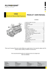
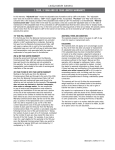
owners manual P-132 P-232 ENGLISH SPANISH FRENCH LPAdjustableBases.com CONTENTS Advisory ...................................................................................................................... 4 LP Sense™ Technology ................................................................................................ 6 Acoustics .................................................................................................................... 7 Fabric Cleaning Information .......................................................................................... 7 Installation ................................................................................................................. 8 Troubleshooting ......................................................................................................... 22 Accessories ............................................................................................................... 24 Adjustable Base 1-3-25 Warranty ................................................................................ 25 Tablet Warranty ......................................................................................................... 26 Spanish translation begins on page 27. La traducción en español inicia en la página 27. French Canadian translation begins on page 51. La traduction en Français débute à la page 51. If adjustable base does not operate or if parts are missing, call: 800-888-3078 Do not contact retail store or dealer. ADVISORY IMPORTANT INFORMATION READ THE FOLLOWING INFORMATION CAREFULLY BEFORE USING THIS PRODUCT FOR OPTIMUM ADJUSTABLE BASE OPERATION, USE A GROUNDED, ELECTRICAL SURGE PROTECTION DEVICE (NOT INCLUDED). FAILURE TO USE A SURGE PROTECTION DEVICE COULD COMPROMISE SAFETY OR CAUSE PRODUCT MALFUNCTION. ELECTRICAL RATING Input - 120VAC, 50/60Hz, 1.8A; Output 29VDC, 7A. ELECTRICAL GROUNDING This product is equipped with a polarized or grounded electrical power cord. The power cord will only fit into a grounded, electrical surge protection device (not included) or a grounded electrical outlet. WARRANTY WARNING Do not open any control boxes, motors or remote control devices (with the exception of the remote control and power down box battery compartments). The product warranty will be void if these components are tampered with. Do not attempt to alter component wiring or adjust or modify the structure of the product in any way or the warranty will be void. Any repair or replacement of base parts must be performed by authorized personnel. PRODUCT RATINGS The base lift motors are not designed for continuous use. Reliable operation and full life expectancy will be realized as long as the lift motor operation does not exceed five (5) minutes over a fifty (50) minute period, or approximately 10% duty cycle. Note: Massage equipped bases are not designed for continuous, extended massage operation. Massage systems are rated for a maximum of 2 hours of use within any 6 hour period. Any attempt to circumvent or exceed product ratings will shorten the life expectancy of the product and may void the warranty. The recommended maximum weight (including mattress) is 700 lb (317 kg) distributed evenly across the base. This product is not designed to support or lift this amount in the head or foot sections alone. Note: Exceeding the recommended weight restrictions could damage the base and void the warranty. For best performance, consumers should enter and exit the adjustable base with the base in the flat (horizontal) position. Avoid placing entire weight on head or foot section of the base, including when in the raised position. DO NOT STAND ON BASE AT ANY TIME. UL (Underwriters Laboratories) recognized components. CFR 1633 approved for use with most mattresses. Assembled in USA. LUBRICATION This product is designed to be maintenance free. The lift motors are permanently lubricated and sealed—no additional lubrication is required. Do not apply lubricant to lift motor lead screws or any nylon nuts or the base may inadvertently creep downward from the elevated position. 4 Premier Series™ Owners Manual 99301419 ADVISORY IMPORTANT INFORMATION READ THE FOLLOWING INFORMATION CAREFULLY BEFORE USING THIS PRODUCT SMALL CHILDREN / PETS WARNING After the base is unboxed, immediately dispose of packaging material as it can smother small children and pets. To avoid injury, children or pets should not be allowed to play under or on the base. Children should not operate this base without adult supervision. PACEMAKER WARNING This product produces a vibrating sensation. It is possible that individuals with heart-assist pacemakers may experience a sensation similar to exercise. Consult physician for complete information. HOSPITAL USE DISCLAIMER This base is designed for in-home use only. It is not approved for hospital use and does not comply with hospital standards. Do not use this base with tent type oxygen therapy equipment, or use near explosive gases. SERVICE REQUIREMENTS Service technicians are not responsible for moving furniture, removing headboards and footboards or any items required to perform maintenance on the base. In the event the technician is unable to perform service due to lack of accessibility, the service call will be billed to the purchaser and the service will have to be rescheduled. PINCH POINT WARNING DURING BASE OPERATION, GAPS (PINCH POINTS) ARE CREATED (ARROWS IN FIGURE 1). A CHILD, A PERSON’S LIMB, OR A PET CAN BECOME ENTRAPPED AT THESE LOCATIONS. DURING USE, AND WHEN BASE IS IN THE RAISED POSITION, ALWAYS KEEP GAP AREAS (PINCH POINTS) CLEAR AND KEEP ALL LIMBS ON TOP OF BASE. FAILURE TO FOLLOW THIS WARNING COULD RESULT IN SERIOUS INJURY OR DEATH. FIGURE 1 TYPICAL PINCH POINTS P-232 MODEL SHOWN FCC COMPLIANCE Components meet Class B digital device rating (Part 15, FCC rules) for residential use. Adjustable bases generate, use and may radiate radio frequency energy. Radio communication may be affected if not installed and operated as recommended in this manual. Changes or modifications not approved by the party responsible for compliance could void the user’s authority to operate the equipment. Radio frequency = 2.4GHz. Premier Series™ Owners Manual 99301419 5 LP Sense™ TECHNOLOGY IMPORTANT INFORMATION READ THE FOLLOWING INFORMATION CAREFULLY BEFORE USING THIS PRODUCT LP Sense™ TECHNOLOGY Your Premier Series™ base is equipped with LP Sense™ technology. LP Sense™ has been engineered to help detect human or animal presence in specific areas of the adjustable base that have moving mechanical parts or potential pinch points. When LP Sense™ is triggered by human or animal contact, your adjustable base will stop movement. To reactivate the base, simply remove the obstruction and continue with the previous function. When LP Sense™ is triggered, the underbed light flashes. When obstruction is removed, underbed light stops flashing. If the base does not begin movement again, please see the Troubleshooting Guide contained within this Owners Manual to reset LP Sense™. The LP Sense™ contact points include the top perimeter of the upholstered surround on a Model P-232, as shown in FIGURE 2. 6 Premier Series™ Owners Manual 99301419 FIGURE 2 TYPICAL LP Sense™ CONTACT POINTS (entire perimeter of upholstered surround on Model P-232) MODEL P-232 SHOWN Although LP Sense™ technology is designed to help prevent human or animal accidents while the base is being adjusted, the presence of LP Sense™ is not a guarantee of safety and does not eliminate the possibility of an accident. DURING USE, AND WHEN BASE IS IN THE RAISED POSITION, ALWAYS KEEP GAP AREAS (PINCH POINTS) CLEAR AND KEEP ALL LIMBS ON TOP OF BASE. FAILURE TO FOLLOW THIS WARNING COULD LEAD TO SERIOUS INJURY OR DEATH. ACOUSTICS LIFTING/LOWERING MECHANISMS The lift/lower feature will emit a minimal humming sound during operation. This is normal. During operation, the lift arm wheels make contact with the platform support of the base. This applies slight tension on the moving components and resonance is reduced to a minimum level. If excessive noise or vibration is experienced, reverse the movement action (up or down) of the base with the remote control. This should realign the base’s activating mechanisms to the proper operational position. LOCATION ENVIRONMENT The level of sound experienced during operation is directly related to the location environment. For example, when a base is located on a hardwood floor with the massage feature in operation, a vibrating tone will be audible. To minimize this resonance, place a piece of carpet, or rubber caster cups, under each leg or caster of the base. It is possible to experience vibration or noise from the headboard brackets, headboards or footboards if mounting bolts are not firmly tightened. MASSAGE OPERATION The massage feature will emit a minimal tone during operation. This is normal. When the massage level is increased, motor resonance will intensify accordingly. FABRIC CLEANING INFORMATION Spot clean only with water based shampoo or foam upholstery cleaner. Pretest a small, inconspicuous area before proceeding. Do not over wet. Do not use solvents to spot clean. Pile fabrics may require brushing with a non-metallic, stiff bristle brush to restore appearance. Hot water extraction or steam cleaning is not a recommended cleaning method. To prevent overall soiling, frequent vacuuming or light brushing with a non-metallic stiff bristle brush to remove dust and grime is recommended. When cleaning a spill, blot immediately to remove spilled material. Clean spots or stains from the outside to the middle of the affected area to prevent circling. Use a professional furniture cleaning service when an overall soiled condition is apparent. Premier Series™ Owners Manual 99301419 7 INSTALLATION For installation and setup, complete the following procedures, in the order indicated below and on the following pages: STEP 1 Before discarding any packing materials, check the adjustable base shipping carton and verify the following items are included: t .BUUSFTT3FUBJOFS t #FE-FHT(varies according to base type) t -PDLJOH-FH$BTUFST(standard w/ steel legs only) t )FBECPBSE#SBDLFU"TTFNCMJFT(varies POWER DOWN KIT OWNERS MANUAL CD according to base type) t )FBECPBSE#SBDLFU)BSEXBSF,JU(blister card) t 1PXFS%PXO,JU t 1PXFS$PSE t 5BCMFUBOEDIBSHJOHDPSE t #FESPPN"DDFTTPSZ$POUSPM t 0XOFST.BOVBM$% t 8BSSBOUZ"DUJWBUJPO$BSE t 2VJDL4FUVQ(VJEF POWER CORD WARRANTY ACTIVATION CARD QUICK SETUP GUIDE MATTRESS RETAINER (1 per base) LOCKING LEG CASTER (4 pieces) Standard with steel leg only. TABLET and charging cord BEDROOM ACCESSORY CONTROL (2) Bracket Weldments* (2) Flange Weldments* 5/16-18 Threads M-8 Threads Blister Card WOOD HEADBOARD BRACKET ASSEMBLIES - HARDWARE *Varies according to base type. Model P-232 type shown. (4 bracket pieces, hardware blister card) 8 Premier Series™ Owners Manual 99301419 Model P-232* STEEL Model P-132* LEG (4 pieces) *Varies according to base type: Either 6” Square Wood Leg or 4” Steel Leg INSTALLATION STEP 2 With packing carton still on adjustable base (with bottom of base exposed), install 4 legs. Simply screw each leg (wood or steel) into a tapped hole at each corner of the base frame (FIGURES 3 and 4). Note: Allowing base to remain in packing carton will prevent it from laying on an unclean surface. WARNING AT LEAST TWO PEOPLE ARE RECOMMENDED FOR HANDLING AND MOVING ADJUSTABLE BASE. STEP 3 Insert casters into the bottom of each base leg, if applicable (FIGURE 4). FIGURE 3 (MODEL P-232) CAUTION FIGURE 4 (MODEL P-132) CASTERS – PRESS-FIT INTO BOTTOM OF LEGS DO NOT ATTEMPT TO SCREW LEGS INTO ANY OTHER INSERTS. THIS WILL DAMAGE PRODUCT. LEGS – SCREW INTO TAPPED HOLE AT EACH CORNER Premier Series™ Owners Manual 99301419 9 INSTALLATION STEP 4 Install batteries in power down battery compartment. a. Locate the power down kit (FIGURE 5). Install the new 9-volt batteries in the power down box. Note: When installing batteries in the power down box, make sure battery wires are routed through notch in box as shown in FIGURE 6. FIGURE 5 POWER DOWN KIT FIGURE 6 10 MAKE SURE WIRE IS ROUTED THROUGH NOTCH IN B0X AS SHOWN. Premier Series™ Owners Manual 99301419 POWER DOWN BOX INSTALLATION b. Attach power down box to floor plate. If necessary, press the tabs in on both sides of the power down box and push in on the compartment until it locks in place (FIGURE 7). FIGURE 7 MAKE SURE WIRE IS ROUTED THROUGH NOTCH AS SHOWN. ATTACH POWER DOWN BOX TO FLOOR PLATE (press in on tabs if needed) POWER DOWN BOX ATTACHED MAKE SURE WIRE IS ROUTED AS SHOWN. FLOOR PLATE c. Insert plug into Power Down 2 port on control box (FIGURE 8). Power down assembly can be placed on floor. FIGURE 8 POWER DOWN 2 PORT CONTROL BOX (attached to underside of base) Premier Series™ Owners Manual 99301419 11 INSTALLATION STEP 5 Remove and extend out power cord from the protective packaging. Plug power cord into power supply (FIGURE 9). Note: Do NOT plug power supply into electrical power outlet yet. FIGURE 9 POWER SUPPLY WARNING POWER CORDS MUST NOT INTERFERE WITH ANY ADJUSTABLE BASE MECHANISMS. STEP 6 Carefully rotate the adjustable base over so it is resting on its legs (FIGURE 10). FIGURE 10 12 Premier Series™ Owners Manual 99301419 INSTALLATION STEP 7 Plug base into electrical power source (FIGURE 11), making sure to avoid making contact with the surround at that time, as this will trip LP Sense™. Note: An electrical surge protection device is recommended (not included). FIGURE 11 ! IMPORTANT ! IF A MODEL P-232 BASE DOES NOT OPERATE, LP SENSE™ MAY BE TRIPPED. CHECK FOR OBSTRUCTION TO UPHOLSTERED SURROUND ASSEMBLY. REMOVE OBSTRUCTION. IF NO OBSTRUCTION, AVOID TOUCHING BASE FOR 72 SECONDS AND BASE WILL RESET ITSELF. STEP 8 Locate and charge tablet by plugging charging cord into USB port located on either side of base (FIGURE 12). Briefly activate all functions of the base with the tablet to verify all features are in working order (see Premier Series™ Tablet User Guide). If base does not operate, refer to the Troubleshooting section of this manual. FIGURE URE 12 USB PORT LOCATED ON SIDE OF BASE, NEAR MIDDLE STEP 9 Return base to the level position. CHARGE TABLET WITH CHARGING CORD Premier Series™ Owners Manual 99301419 13 INSTALLATION STEP 10 Install mattress retainer at the foot end of the adjustable base as follows: a. Locate grommeted holes at foot of base. b. Place mattress retainer ends into grommeted holes in top surface of adjustable base (FIGURE 13). Press down until horizontal retainer section is flush against base. FIGURE 13 MATTRESS RETAINER FO OT EN DO FB AS E NOTE: If base is to be set up without a headboard, basic installation is now complete. If headboard is to be installed, proceed to Headboard Bracket Installation. 14 Premier Series™ Owners Manual 99301419 INSTALLATION HEADBOARD BRACKET INSTALLATION NOTE FAILURE TO FOLLOW HEADBOARD BRACKET INSTALLATION INSTRUCTIONS MAY CAUSE HEADBOARD BRACKET INTERFERENCE WITH BASE FOAM DURING BASE OPERATION. BASE FOAM OR BASE COVER DAMAGE COULD RESULT. WARNING IN ORDER TO AVOID A PERSON OR PET BEING CAUGHT IN THE SPACE REFERENCED BELOW WHILE THE BASE IS IN MOTION, THE BOTTOM OF THE HEADBOARD CROSS MEMBER MUST BE POSITIONED SO THAT THERE IS NO MORE THAN 3 INCHES (76.2mm) BETWEEN THE HEADBOARD AND THE TOP OF THE MATTRESS (FIGURE 14). DO NOT EXCEED 3 INCHES (76.2mm). FAILURE TO FOLLOW THIS INSTRUCTION COULD RESULT IN SERIOUS PERSONAL INJURY OR DEATH. FIGURE 14 3 s he inc X. MA Premier Series™ Owners Manual 99301419 15 INSTALLATION STEP 11a (for Model P-232) Install headboard brackets to the adjustable base frame as follows: a. Using the tablet, raise the head section of the base as far as it will articulate to gain access to the adjustable base frame. b. Insert a 1/2” carriage bolt into a headboard bracket weldment (FIGURE 15). FIGURE 15 HEADBOARD BRACKET WELDMENT 1/2” CARRIAGE BOLT 16 Premier Series™ Owners Manual 99301419 INSTALLATION c. Locate (2) slotted holes in base frame at one corner of head end of base. Place the headboard bracket weldment underneath base frame and against the head end of the base, positioning the bracket weldment so the carriage bolt appears through the innermost slotted hole in the base frame (FIGURE 16). Place hex nut on 1/2” long carriage bolt to attach bracket weldment to base frame. Loosely tighten to allow adjustment for headboard hole alignment. Place second 1/2” long carriage bolt in remaining slot and secure using hex nut. Loosely tighten to allow adjustment for headboard hole alignment. HEADBOARD BRACKET WELDMENT FIGURE 16 FRAME SLOTS 1/2 INCH LONG CARRIAGE BOLT HEAD END OF BASE Premier Series™ Owners Manual 99301419 17 INSTALLATION d. Place headboard flange weldment against headboard bracket weldment. Install (2) 1” long hex bolts through slots in headboard bracket weldment and holes in headboard flange weldment (FIGURE 17). Secure using (2) hex nuts. Loosely tighten to allow adjustment for headboard hole alignment. FIGURE 17 KET RAC IN OR B E SLID BLIES IEVE EM CH ASS T TO A ION U T I O POS HEADBOARD BRACKET WELDMENT SLOTS 1 INCH LONG HEX HEAD BOLT HEADBOARD FLANGE WELDMENT e. Repeat procedure to attach the other headboard bracket assembly (FIGURE 18). FIGURE 18 SLIDE BRAC ASSE KET MB OUT T LIES IN OR O ACH POSIT IEVE ION USE (2) 1 INCH LONG HEX HEAD BOLTS TO ATTACH FLANGE WELDMENT TO BRACKET WELDMENT 18 Premier Series™ Owners Manual 99301419 INSTALLATION h. Measure the center-to-center distance between the mounting slots of the headboard bracket flanges (FIGURE 19). i. If bracket flange adjustment is required to accept the headboard, remove the 1 inch long hex head bolts and move flanges side-to-side for the adjustment (FIGURE 19). Reinstall bolts. Tighten all headboard mounting bolts. j. Firmly tighten all bolts of both headboard bracket assemblies. k. Install headboard. FIGURE 19 MEASURE FLANGE SLOTS CENTER-TO-CENTER TO CHECK HEADBOARD HOLE LOCATION REMOVE 1 INCH LONG HEX HEAD BOLTS AND RELOCATE FLANGES TO ACHIEVE CENTER-TO-CENTER DISTANCE REQUIRED FOR HEADBOARD MOUNTING HOLES Premier Series™ Owners Manual 99301419 19 INSTALLATION STEP 11b (for Model P-132) Install headboard brackets to the adjustable base frame as follows: a. Using the tablet, raise the head section of the base as far as it will articulate to gain access to the adjustable base frame. b. Slide one headboard bracket channel onto one side of the base frame. Using (2) carriage bolts/nuts attach channel to base frame (FIGURE 20). Hand tighten bolts/nuts (loosely) to allow adjustment of the headboard bracket channels. Repeat procedure to install the other headboard bracket channel to the other side. FIGURE 20 USE (2) 3 INCH CARRIAGE BOLTS AND NUTS TO ATTACH EACH BRACKET CHANNEL TO BASE FRAME EXTENSION BASE FRAME 20 SLIDE HEADBOARD BRACKET CHANNEL OVER THE BASE FRAME EXTENSION Premier Series™ Owners Manual 99301419 INSTALLATION c. Attach one headboard bracket flange to one of the bracket channels with (2) hex head bolts/nuts (FIGURE 21). Tighten bolts. Repeat procedure to attach the other headboard bracket flange. d. Slide headboard bracket assemblies (in or out) to achieve a distance of 1.5 inches (38.1mm) to 2 inches (50.8mm) between the edge of the base and headboard bracket flange assemblies (FIGURE 21). e. Firmly tighten the 3 inch carriage bolts of both headboard bracket channels. f. Measure the distance (center-to-center) between the mounting holes in the headboard. g. Measure the center-to-center distance between the mounting slots of the headboard bracket flanges. h. If bracket flange adjustment is required to accept the headboard, remove the 1 inch headboard bracket flange bolts and move flanges side-to-side for the adjustment (FIGURE 21). Reinstall bolts and tighten. i. Install headboard. FIGURE 21 HEADBOARD BRACKET FLANGE K ET RAC IN OR B E S SLIDMBLIE HIEVE C E A S AS T TO TION OU POSI NOTE TWIN SIZE HEADBOARD BRACKET ASSEMBLIES ARE SHOWN (FIGURE 21). QUEEN SIZE HEADBOARD BRACKETS ARE EQUIPPED WITH ANGLE BRACES. USE (2) 1 INCH LONG HEX HEAD BOLTS AND NUTS (TIGHTEN) TO ATTACH BRACKET FLANGE TO BRACKET CHANNEL STEP 12 Install mattress on adjustable base. Typical Premier Series™ adjustable base installation is now complete. Premier Series™ Owners Manual 99301419 21 TROUBLESHOOTING In the event the adjustable base fails to operate, investigate the symptoms and possible solutions provided in the chart below: SYMPTOM SOLUTION t7FSJGZQPXFSDPSEJTQMVHHFEJOUPBXPSLJOHHSPVOEFE electrical outlet. A grounded, electrical surge protection device is recommended. Test outlet by plugging in another working appliance. t -14FOTFJTUSJQQFE$IFDLGPSPCTUSVDUJPOUP upholstered surround assembly. Remove obstruction. t 8BJUTFDPOETBOECBTFXJMMSFTFUJUTFMG Tablet is active and appears to be operable, but will not activate base. t6OQMVHCBTF8BJUTFDPOETUIFOQMVHCBDLJO t7FSJGZ#MVFUPPUIDPOOFDUJPO1SPHSBNUIFUBCMFU (see separate Tablet User Guide for programming procedures). t&MFDUSJDBMDJSDVJUCSFBLFSNBZCFUSJQQFE$IFDL electrical service breaker box to verify. t%FGFDUJWFTVSHFQSPUFDUJPOEFWJDFPSFMFDUSJDBMPVUMFU Test outlet by plugging in another working appliance. Tablet will not illuminate. t1SFTTBOEIPME0/0''CVUUPOTFDPOETVOUJMEJTQMBZ appears. If display does not appear, battery is dead. t$IBSHFUBCMFUXJUIXBMMDIBSHFS. t#BTFNFDIBOJTNNBZCFPCTUSVDUFE&MFWBUFCBTFBOE check for obstruction. Remove obstruction. Head or foot section will elevate, but will not return to the horizontal (flat) position. t)FBETFDUJPONBZCFUPPDMPTFUPUIFXBMM t)FBECPBSENBZCFUPPDMPTFUPUIFFEHFPGUIFNBUUSFTT Verify a 1.5” (38.1mm) to 2” (50.8mm) distance between headboard brackets and mattress. Adjust if required. t6OQMVHCBTF8BJUTFDPOETUIFOQMVHCBDLJO t-PTTPG"$QPXFSUPDPOUSPMCPY7FSJGZQPXFSTPVSDFJT active. Head and/or foot sections of base only move downward (slowly). t#BTFJTPQFSBUJOHJOCBDLVQNPEF7FSJGZQPXFSTPVSDF is active and replace power down batteries (power down feature is for one time use only) in control box. Underbed light is flashing. t-14FOTFJTUSJQQFE3FNPWFPCTUSVDUJPO Continued on next page... 22 Premier Series™ Owners Manual 99301419 TROUBLESHOOTING In the event the adjustable base fails to operate, investigate the symptoms and possible solutions provided in the chart below: SYMPTOM SOLUTION t7FSJGZNBUUSFTTSFUBJOFSXBTSFNPWFEEVSJOHJOTUBMMBUJPO Remove mattress retainer if still attached to the underneath side of base. t*GCBTFJTMPDBUFEPOIBSETVSGBDFnPPSJOHQMBDFDBSQFU pieces or rubber caster cups under each leg or caster of the base. &YDFTTJWFNBTTBHFNPUPSOPJTF t&MFWBUFUIFIFBEPSGPPUTFDUJPOBTIPSUEJTUBODFXJUI the tablet) to realign the lift/lower mechanisms with the base support platform. t7FSJGZUIBUUIFCBTFJTOPUQPTJUJPOFEBHBJOTUBXBMM nightstand, or other object that may cause vibration or noise. t*GCBTFJTJOTUBMMFEPWFSBCBTFGSBNFWFSJGZNBTTBHF motors are not causing base frame (or base frame components) to vibrate. t7FSJGZUIBUIFBECPBSEBUUBDINFOUIBSEXBSFJTUJHIUFOFE firmly (if used). Premier Series™ Owners Manual 99301419 23 ACCESSORIES OPTIONAL EQUIPMENT Contact customer service toll free (800-888-3078) to order the accessories indicated in the chart below. ACCESSORY DESCRIPTION 24 CODE Bedroom Accessory Control 4B8056 *OTVMBUFE)FBECPBSE#SBDLFU,JU5XJO4QMJU$BM,JOH 4B7728 *OTVMBUFE)FBECPBSE#SBDLFU,JU2VFFO'VMM 4B7729 *OTVMBUFE)FBECPBSE#SBDLFU,JU(2 piece base) 4B7730 w9w0%-FH"EBQUFS,JU(for use with Model P-132) 4B7365 w0%-FH"EBQUFS,JU(for use with Model P-232) 4B7275 Premier Series™ Owners Manual 99301419 IMAGE ADJUSTABLE BASE 1 YEAR, 3 YEAR AND 25 YEAR LIMITED WARRANTY In this warranty: “Adjustable base” means the adjustable bed foundation sold by L&P to the dealer. The “adjustable base” does not include the mattress or tablet. “L&P” means Leggett & Platt, Incorporated. “Purchaser” and “You” both mean the consumer who is the original purchaser of this adjustable base made by L&P. This warranty is not transferrable. “Warranty Commencement Date” means either (i) the date You purchased a new and unused L&P adjustable base or (ii) the date of manufacture of this adjustable base if You purchased an L&P adjustable base that has been used as floor or display model. L&P warrants this adjustable base to You on the terms and over the reducing periods of time set out below. All warranty claims require notice from You to be given to L&P in the manner set out below, and to be received by L&P inside the applicable warranty time period. 1ST YEAR FULL WARRANTY For the first year from the Warranty Commencement Date, your adjustable base is warranted against non-excluded defects in L&P’s workmanship or materials. During the first year from the Warranty Commencement Date, L&P will repair or replace (at no cost to You) any defective adjustable base part, and L&P will pay all authorized labor and transportation costs associated with the repair or replacement of any parts found to be defective. 2ND & 3RD YEAR LIMITED WARRANTY During the second and third year from the Warranty Commencement Date, L&P will replace any adjustable base part found to be defective and not excluded by this warranty. You are responsible to pay all service and transportation costs related to the costs of receiving and installation of the new part. Repair or replacement shall be the sole remedy of the Purchaser. There shall be no liability on the part of L&P for any special, indirect, incidental, or consequential damages or for any other damage, claim, or loss not expressly covered by the terms of this warranty. This limited warranty does not include reimbursement for inconvenience, removal, installation, setup time, loss of use, shipping, or any other costs or expenses. L&P and its service technicians will not be responsible for moving furniture or any other items not attached to the adjustable base in order to perform service on the adjustable base. It is the sole responsibility of You to provide adequate space and accessibility to the adjustable base. In the event that the technician is unable to perform service due to lack of accessibility, the service call will be billed to You and the service will have to be rescheduled. 4TH YEAR TO END OF 25TH YEAR LIMITED WARRANTY Starting in the fourth year from the Warranty Commencement Date and through to the end of the 25th year from the Warranty Commencement Date, L&P will replace steel and mechanical base parts found to be defective and not excluded by this warranty. This warranty does not cover any electronics, electrical components, drive motors or massage motors. You are responsible to pay all service and transportation costs related to receiving and installation of the new part and a portion of the cost of the replacement steel and mechanical part, based on the number of months that the base has been owned by you since the fourth anniversary of the Warranty Commencement Date. By the end of the 25th year, no portion of the replacement cost is covered by L&P. You will be required to pay 1/22nd of the then current replacement cost of the part multiplied by the number of years past the third year from the Warranty Commencement Date. This portion is calculated using the following formula: Cost of the part divided by 22 [being the number of years in years 4 to 25 inclusive], multiplied by the number of years you have owned the base since the end of the first 3 years. For example, if you make a claim for a part eligible for this warranty in the 5th year since the Warranty Commencement Date, you would be responsible for paying: $100 part cost divided by 22, multiplied by 2 = $9.09. L&P makes no other warranty whatever, express or implied, and all implied warranties of merchantability and fitness for a particular purpose are disclaimed by L&P and excluded from this agreement. ADDITIONAL TERMS AND CONDITIONS This warranty requires notice to be given to L&P of any claim for repairs or replacement parts. toll free phone: 1.800.888.3078 EXCLUSIONS: This warranty does not apply; (a) to any damage caused by You; (b) if there has been any repair or replacement of adjustable base parts by an unauthorized person; (c) if the adjustable base has been mishandled (whether in transit or by other means), subjected to physical or electrical abuse or misuse, or otherwise operated in any manner inconsistent with the operation and maintenance procedures outlined in the Owner’s Manual and this warranty; (d) to damage to mattresses, fabric, cables, electrical cords or items supplied by dealers (contact the dealer for warranty information on these items); (e) if there has been any modification of the adjustable base without prior written consent by L&P; or (f) to costs for unnecessary service calls, including costs for in-home service calls solely for the purpose of educating You about the adjustable base or finding a satisfactory power connection. email: [email protected] Some American States do not allow the exclusion or limitation of incidental or consequential damages, so the above limitation or exclusion may not apply to You. This warranty gives You specific legal rights, and You may also have other rights, which may vary from jurisdiction to jurisdiction. This warranty is valid in all 50 American States, the District of Columbia, Puerto Rico, and all 10 Provinces and 3 Territories of Canada. For customer service under this limited warranty, give notice to L&P by mail, phone, email or online to the addresses set out below: Leggett & Platt, Incorporated PO Box 668 Lexington, North Carolina 27293 online: lpadjustablebases.com For French Canadian Customer Service, call 1.877.452.2665 PLEASE DO NOT CONTACT YOUR RETAIL DEALER OR ANY OTHER SERVICE PERSONNEL This warranty will be void if either the recommended weight restriction is not followed (refer to the advisory section of the Owner’s Manual) or if You sell or give or transfer the base to another person. Any repairs to or replacement to Your adjustable base or its components under the terms of this limited warranty does not extend the applicable warranty from the Warranty Commencement Date. This time limitation may OPUBQQMZJOTPNFKVSJTEJDUJPOTJODMVEJOHUIF1SPWJODFPG2VFCFD The decision to repair or to replace defective parts under this warranty shall be made, or cause to be made, by L&P at its option and in its sole discretion. Premier Series™ Owners Manual 99301419 25 TABLET WARRANTY In this warranty: “Tablet” means the hand-held, touch-screen device provided with the Premier Series™ adjustable base sold by L&P to the dealer. “L&P” means Leggett & Platt, Incorporated. “Purchaser” and “You” both mean the consumer who is the original purchaser of this adjustable base Tablet provided by L&P. This warranty is not transferable. “Warranty Commencement Date” means either (i) the date You purchased a new and unused L&P Premier Series™ adjustable base with Tablet or (ii) the date of manufacture of the Premier Series™ adjustable base with Tablet if You purchased a Premier Series™ adjustable base with Tablet that has been used as a floor or display model. L&P warrants this Tablet to You on the terms and over the reducing periods of time set out below. All warranty claims require notice from You to be given to L&P in the manner set out below, and to be received by L&P inside the applicable warranty time period. 1ST 6 MONTHS FULL WARRANTY For the first six (6) months from the Warranty Commencement Date, your Premier Series™ adjustable base Tablet is warranted against non-excluded defects in workmanship or materials. During the first six (6) months from the Warranty Commencement Date, L&P will repair or replace (at no cost to You) any defective Tablet component and L&P will pay all authorized labor and transportation costs associated with the repair or replacement of any Tablet components found to be defective. Any repairs to or replacement of Your Tablet or its components under the terms of this limited warranty does not extend the applicable warranty from the Warranty Commencement Date. This time limitation may not apply in TPNFKVSJTEJDUJPOTJODMVEJOHUIF1SPWJODFPG2VFCFD 7 MONTHS TO END OF 1ST YEAR LIMITED WARRANTY (6 Months Prorated) Starting at the beginning of the seventh (7th) month from the Warranty Commencement Date and through to the end of the first (1st) year from the Warranty Commencement Date, L&P will replace, within the terms and conditions set forth in this warranty, Tablet components found to be defective and not excluded by this warranty. The one (1) month Tablet prorate determination is $22.00 based on a consumer retail Tablet price of $132.00. Repair or replacement shall be the sole remedy of the Purchaser. There shall be no liability on the part of L&P for any special, indirect, incidental, or consequential damages or for any other damage, claim, or loss not expressly covered by the terms of this warranty. &YBNQMF#FHJOOJOHBUBOEUISPVHI UIFUINPOUIPGUIJTMJNJUFE warranty, You will be required to pay $22.00 for a repaired or replacement Tablet. Beginning at (and through) the 8th month, You will be required to pay $44.00 for a repaired or replacement Tablet. Beginning at (and through) the 9th month, You will be required to pay $66.00 for a repaired or replacement Tablet, etc. L&P makes no other warranty whatever, express or implied, and all implied warranties of merchantability and fitness for a particular purpose are disclaimed by L&P and excluded from this agreement. Note: All dollar values indicated in this limited Tablet warranty are subject to change per market location or other determining factors and L&P reserves the right to authorize or change dollar values indicated herein. You are required to pay all shipping and handling costs or any other transportation or service costs associated with receiving a repaired or replacement Tablet. At the completion of the first (1st) year, no portion of the replacement cost is covered by this limited L&P Premier Series™ tablet warranty. EXCLUSIONS: This warranty does not apply to the following: (a) abuse or misuse, including but not solely limited to the failure to use this product for its normal purposes or in accordance with instructions on usage and maintenance (dropping etc.); (b) defects resulting from usage of the product in conjunction with accessories that are not approved by L&P for use with this product (impedance of headsets etc.); (c) failure of the product resulting from incorrect installation or use not consistent with the instructions and technical or safety standards prescribed in this user manual; (d) accidents, Acts of God, lightning, water, fire, public disturbances, improper ventilation, voltage fluctuations, dropping in or splashing with water or any cause beyond the control of L&P; (e) unauthorized modifications carried out to the product in order to comply with local or international technical standards in countries for which this L&P product was not originally designed (voltage converters, different battery, etc.); (f) damage of the battery caused by overcharging or failure to use in accordance with the specific instructions outlined in this user manual; (g) the serial number on the product has been altered, deleted, removed or made illegible; (h) the batteries are charged by chargers other than those approved by L&P specific to this Tablet; (i) any of the seals on the battery enclosure or cells are broken or show evidence of tampering; (j) use of software on this Tablet that is not approved for use on the device. This warranty will be void if any unauthorized or unapproved software is loaded on this Tablet or You sell or give or transfer the Tablet to another person. 26 Premier Series™ Owners Manual 99301419 The decision to repair or to replace a defective Tablet under this warranty shall be made, or cause to be made, by L&P at its option and in its sole discretion. This limited warranty does not include reimbursement for inconvenience, removal, installation, setup time, loss of use, shipping, or any other costs or expenses. Some American States do not allow the exclusion or limitation of incidental or consequential damages, so the limitation or exclusion may not apply to You. This warranty gives You specific legal rights, and You may also have other rights, which may vary from jurisdiction to jurisdiction. This warranty is valid in all 50 American States, the District of Columbia, Puerto Rico, and the 10 Provinces and 3 Territories of Canada. For customer service under this limited warranty, give notice to L&P by mail, phone, email or online to the addresses set out below: Leggett & Platt, Incorporated PO Box 668 Lexington, North Carolina 27293 toll free phone: 1.800.888.3078 online: lpadjustablebases.com email: [email protected] For French Canadian Customer Service, call 1.877.452.2665 PLEASE DO NOT CONTACT YOUR RETAIL DEALER OR ANY OTHER SERVICE PERSONNEL