1
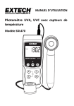
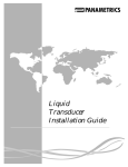
S 4345/4350 PDA DETECTOR
USER MANUAL
VERSION 1.0 (2013-01-08)
2
TABLE OF CONTENTS
1.Introduction
1.1 How to Use this Manual
1.1.1 Symbols
1.2 Safety Information
1.2.1
1.2.2
1.2.3
1.2.4
General Safety Information
Intended Purpose
Environmental Safety
Electrical Safety
2. Instrument Overview
2.1 General Instrument Overview
3. Instrument Description
3.1 General Instrument Description
3.1.1 Front Panel Description
3.1.2 Back Panel Description
3.2 Functional Description
3.2.1 Front Elements
3.2.2 Functional Elements (256 Diodes)
3.2.2 Functional Elements (1024 Diodes)
4. Instrument Setup
4.1Unpacking
4.2 Capillary Connections
4.3 Backside Connections
4.3.1 Electrical Connections
5. Instrument Menus
5.1Keyboard
5
5
5
6
6
6
6
7
9
9
11
11
11
13
14
14
15
16
17
17
17
18
18
19
5.2 Status Screen
5.3 Menu Description 20
21
6. Instrument Operation
25
5.3.1 Submenu: PDA Lamp Info
5.3.2 Submenu: System
6.1Overview
6.1.1 LAN Mode
6.1.2 DHCP Mode
6.1.3 RS232 Mode
7. Instrument Maintenance
7.1Flowcell
7.1.1 Flowcell Assembly
22
23
25
25
25
25
27
27
27
7.2 Deuterium & Tungsten Lamps
28
Appendix A: Specifications
29
7.2.1 Lamp Exchange
A.1 Technical Specifications
A.2 Environmental Conditions
A.2.1 Operational Conditions
A.2.2 Storage Conditions
28
29
30
30
30
Appendix B: Accessories
31
Appendix C: Version Control
33
B.1 Standard Accessories
C.1 Version History
31
33
19
3
4
1.INTRODUCTION
1.1 How to Use this Manual
This manual is designed as a reference to the installation, operation and
maintenance of the S 4345/4350 PDA Detector.
It is strongly recommended to review this manual before operating the instrument.
The content of this manual is subject to change without notice. This document is believed to be complete and accurate at the time of publication.
The Manufacturer is not liable for any damage resulted from the use of this
manual.
1.1.1 Symbols
Throughout this manual important text sections are marked with the following symbols:
This section includes important information which may result in instrument or personal damage if not carefully followed.
This section includes important information for the proper operation of the instrument. Failure to follow this information may result in
faulty behaviour of the instrument and/or wrong analysis results.
This section emphasis some detailed information intended to optimize
the performance of the instrument or to give a better understanding of
some technical details.
STOP !
!
WARNING
NOTE
5
1.2 Safety Information
This instrument is compliant with all related standards as stated in Appendix B.
1.2.1 General Safety Information
The operation of any analytical instrumentation requires the operator to be
familiar with the potential hazards of using chemical solvents.
To avoid personal injury and/or damage to the instrument the operator is
responsible to follow all safety information herein.
The manufacturer assumes no liability for any damage resulted from not
following any of these safety procedures.
1.2.2 Intended Purpose
This instrument is designed and certified as a general purpose laboratory
instrument for research and routine analysis work only. It is not certified
for in-vitro or other medical applications.
Any use outside this intended purpose does not fall with the manufacturer’s liability.
1.2.3 Environmental Safety
Only operate the instrument in well-ventilated areas. If volatile or flammable solvents are used with this instrument, arrange for proper disposal
of any waste and/or fumes.
Always properly dispose any waste solvents.
Avoid open flames and sparks when working with flammable and volatile
solvents.
In case of instrument leakage, turn off the instrument and remedy the leakage problem immediately.
6
1.2.4 Electrical Safety
Always use the provided power cords.
Replace faulty power cords and other cables before operating the instrument.
Always replace blown fuses with original spare fuses.
When the instrument’s housing is open, electrical connections will be exposed. Disconnect the instrument from the main power before opening
the housing.
The housing should only be opened by certified service personnel!
Damage of the instrument of injury may result from improper handling.
STOP !
7
8
2.INSTRUMENT OVERVIEW
2.1 General Instrument Overview
The S 4345/4350 PDA Detector is a photo-diode-array (PDA) detector for
routine analysis and sophisticated research. The dual lamp design offers a
wavelength range of 190 – 720 nm (256 Diodes) or 190 – 1015 nm (1024
diodes) with a low baseline noise. The front-accessible flowcell can easily be exchanged, as can be the lamps which are accessible through a side
panel in the instrument housing.
4-Channel Detector
The S 4345/4350 PDA Detector features 4-Wavelength channels to measure
chromatograms at 4 different wavelengths at the same time. With this feature the optimum wavelength can be selected for each analyzed substance.
Optional – Ananlog Output
The S 4345/4350 PDA Detector is available with an optional 4-Channel
analog output. This D/A converter output option is offered to keep the system flexible to be used with any data acquisition software available.
9
Figure: S 4345/4350 Optical Module (256-Diodes)
10
3.INSTRUMENT DESCRIPTION
3.1 General Instrument Description
3.1.1 Front Panel Description
The front panel of the S 4345/4350 PDA Detector consists of three main
elements: the TFT Display (1), the Keyboard (2) and the Front Cover (3).
The 3” TFT Display shows the current status information and is used with
the Keyboard to adjust instrument settings and fully operate the instrument in stand-alone mode without a PC required.
The Front Cover has a view panel, so that the important parts are always
visible to the operator. In case of a leak it can be detected before solvents are
leaking out of the bottom of the Front Cover.
The Front Cover can be opened to easily access the flowcell.
#
Element
1
TFT Display
2
Keyboard
3
Front Cover
11
Removing the Front Cover
The Front Cover of the S 4345/4350 PDA Detector is completely removable at its hinges.
• Open The Front Cover to 90° (in order to get free of any instrument
stacked on top)
• Remove the Front Cover
• Store the Front Cover at a safe place
12
3.1.2 Back Panel Description
The back panel of the S 4345/4350 PDA Detector houses the power and
interface connectors and several drain outlets.
The Power Cord Connection & Power Switch housing holds the main fuse
in an internal fuse carrier.
The digital I/O and other interface connectors are used for remote instrument control and are discussed in a later chapter.
#
Element
1
Instrument Serial Number
2
Power Cord Connection &
Power Switch
3
Remote Digital I/O Connector
4
LAN Interface Connector
5
RS-232 Interface Connectors
6
RS-485 Interface Connector
13
3.2 Functional Description
3.2.1 Front Elements
The S 4345/4350 PDA Detector has all important parts directly accessible
from the front panel when the Front Cover is opened or removed.
The Capillary Holder (3) holds the pump inlet capillary in place.
The flowcell (4) is completely accessible from the front to make capillary
connections to the flwcell inlet (5) and outlet (6) and can be easily removed
with 2 screws..
#
Element
1
TFT Display
2
Keyboard
3
Capillary Holder
4
Flowcell
5
Flowcell Inlet
6
Flowcell Outlet
14
3.2.2 Functional Elements (256 Diodes)
All functional elements of the S 4345/4350 PDA Detector are located inside the instrument.
The Display PCB (1) controls the TFT Display and Keyboard. It is accessible when the display panel is removed.
The Lamp Power Supply Unit (2) supplies the required voltage and ignition
sequence for the Deuterium lamp.
The Power Supply Unit (3) supplies 24V to the PCB’s. The input voltage is
variable from 90 V to 240 V (5).
The Controlled PCB (4) controls the whole pump.
The Fan (6) is mounted on the back panel and is important for regulating
the internal temperature.
The Lamp Connector Rack (7) is used for easy connection of Deuterium
and Tungsten lamps from the side panel of the instrument.
#
Element
1
Display PCB
2
D2-Lamp Power Supply
3
24V Power Supply Unit
4
Controller PCB
5
Mains Connector
6
Fan
7
Lamp Connector Bracket
8
Optical Module
15
3.2.2 Functional Elements (1024 Diodes)
All functional elements of the S 4345/4350 PDA Detector are located inside the instrument.
The Display PCB (1) controls the TFT Display and Keyboard. It is accessible when the display panel is removed.
The Lamp Power Supply Unit (2) supplies the required voltage and ignition
sequence for the Deuterium lamp.
The Power Supply Unit (3) supplies 24V to the PCB’s. The input voltage is
variable from 90 V to 240 V (5).
The Controlled PCB (4) controls the whole pump.
The Fan (6) is mounted on the back panel and is important for regulating
the internal temperature.
The Lamp Connector Rack (7) is used for easy connection of Deuterium
and Tungsten lamps from the side panel of the instrument.
#
Element
1
Display PCB
2
D2-Lamp Power Supply
3
24V Power Supply Unit
4
Controller PCB
5
Mains Connector
6
Fan
7
Lamp Connector Bracket
8
Optical Module
16
4.INSTRUMENT SETUP
4.1Unpacking
Remove the S 4345/4350 PDA Detector from its package and put it on the
working desk. Check the instrument thoroughly for any damage that may
have occurred during shipping. Contact your supplier in case of any damages.
Check the accessories shipped with the instrument if everything is complete and in good condition.
4.2 Capillary Connections
Connect the capillary coming from the separation column to the flowcell
inlet (4). Then connect the drain capillary to the flowcell outlet (3).
#
Element
1
Capillary Holder
2
Flowcell
3
Flowcell Outlet
4
Flowcell Inlet
17
4.3 Backside Connections
4.3.1 Electrical Connections
• Connect the supplied power cord to the Mains connector (2).
• Connect the supplied RS-232 cable to the RS-232 connector (4) if
the instrument is to be operated by PC
• Connect the remote control wires to the Digital I/O connector (3) if
the instrument is to be run in External mode.
Please refer to 5. Instrument Operation for further information about PC
control and Remote control.
#
Element
1
Serial Number
2
Mains connector
3
Remote Digital I/O
4
RS-232 Serial Communication
5
RS-485 Communication Bus
6
USB Communication
(not in use)
18
5.INSTRUMENT MENUS
5.1Keyboard
The S 4345/4350 PDA Detector parameters can be adjusted at any time via
the screen menu and keyboard on the front panel.
[MENU] Key
With the [MENU] key you can access the Main Menu and select a submenu.
[STATUS] Key
With the [STATUS] key you can access the status screen from any menu.
[EDIT] Key
Use the [EDIT] key to change any parameters. When you press the [EDIT]
key, the selected parameter can be changed. Confirm the new setting by
pressing the [EDIT] key again.
[CANCEL] Key
With the [CANCEL] key you can abort the change of a parameter. When
pressing [CANCEL] key instead of [EDIT] key when changing a parameter, the change is discarded and the original value is used.
[CURSOR] Keys
The 4 arrow [CURSOR] keys are used to navigate the menus.
[ZERO] Key
The [ZERO] key sets the baseline absorption value to zero.
19
[PROG] Key
The [PROG] key starts the wavelength program (not in use).
5.2 Status Screen
The Status Screen shows the most important parameters.
Mode
The top line shows the currently selected mode: RS232, DHCP, or LAN.
Status
On the top right the current status is displayed: Run, Error
IP Address
The currently selected IP Address.
20
5.3 Menu Description With the [MENU] key, the Main Menu is displayed.
Use the [CURSOR] key ([UP] and [DOWN]) to browse through the Main
Menu for access of one of the Submenus.
21
5.3.1 Submenu: PDA Lamp Info
D2 State
Select the Deuterium lamp state: ON or OFF.
D2 Total Runtime
The total runtime of the deuterium lamp in hours..
D2 Total Ignitions
The total number of ignitions of the deuterium lamp.
Vis State
Select the desired Tungsten lamp state: ON or OFF.
Vis Total Ignitions
The total number of ignitions of the tungsten lamp.
22
5.3.2 Submenu: System
COM-Mode
Select the communication mode of the detector: LAN, DHCP, or RS232.
IP Addr
Enter the desired IP Address if running in LAN Mode.
SubMask
Enter the desired Subnet Mask if running in LAN or DHCP Mode.
Display Version
The firmware version of the display.
Mainboard Version
The firmware version of the mainboard.
23
24
6.INSTRUMENT OPERATION
6.1Overview
The S 4345/4350 PDA Detector can be operated in 3 different Operation
Modes: LAN, DHCP, or RS232
6.1.1 LAN Mode
In LAN Mode the instrument is controlled via LAN with a static IP Address.
6.1.2 DHCP Mode
In DHCP Mode the instrument is controlled via LAN with dynamic IP Address from the DHCP server. ATTENTION: With high network traffic the
data communication might be unstable and can lead to lost data!
6.1.3 RS232 Mode
In RS232 Mode the instrument is controlled by a PC software (e.g. Clarity)
via RS-232 serial line. The data rate is limited to 5 Hz in this Mode.
25
26
7.INSTRUMENT MAINTENANCE
7.1Flowcell
7.1.1 Flowcell Assembly
The following diagram shows all the components of the dismantled flowcell:
#
Element
1
Holding Screw (SS)
2
Centering Disc (PEEK)
3
Quartz Lens
4
PTFE Sealing
27
7.2 Deuterium & Tungsten Lamps
7.2.1 Lamp Exchange
The lamps can be accessed from the left side panel of the instrument.
• Remove the side panel to access the lamps
#
Element
1
Deuterium Lamp
2
Tungsten Lamp
3
Tungsten Lamp Conector
4
Deuterium Lamp Connector
Exchange Deuterium Lamp
After opening the side panel, the Deuterium Lamp can be accessed.
• remove the Deuterium Lamp by loosening the top and bottom
screw (1)
• disconnect the Deuterium Lamp (4)
Now, the Deuterium Lamp can be removed and a new lamp inserted.
Exchange Tungsten Lamp
After opening the side panel, the Tungsten Lamp can be accessed.
• remove the Tungsten Lamp by loosening the PEEK finger-screw on
top of the Tungsten Lamp housing (2)
• disconnect the Tungsten Lamp (3)
Now the Tungsten Lamp can be removed and replaced by a new lamp.
28
APPENDIX A: SPECIFICATIONS
A.1 Technical Specifications
Wetted Materials:
Baseline Noise:
Baseline Drift:
Number of Diodes:
Wavelength Range:
Wavelength Accuracy:
Mean Pixel Pitch:
Linearity
Light Source:
Wavelength Program:
Analog Output
Data Rate
Dimensions:
Weight:
Power Supply:
Stainless Steel / PEEK*, PTFE, Quartz
± 1 x 10⁻⁵ AU (@240nm, 2 sec Risetime)
< 3 x 10⁻⁴ AU/h
256 or 1024
256-Diodes: 190 - 720 nm
1024-Diodes: 190 - 1015 nm
0.5 nm (256 Diodes); 0.3 nm (1024 Diodes)
2.2 nm (256 Diodes), 0.8 nm (1024 Diodes)
> 2.0 AU
Deuterium Lamp, Tungsten Lamp
Programmable, 10 steps
- (optional: 4x 1 V)
1 Hz - 100 Hz
396 x 165 x 478 mm (W x H x D)
7.0 kg
100 – 250 ~V, 47 – 63 Hz
* depending on material option
29
A.2 Environmental Conditions
A.2.1 Operational Conditions
Ambient Temperature:
Ambient Relative Humidity:
+10 °C to +35 °C
20 to 80 % RH (non-condensing)
A.2.2 Storage Conditions
Ambient Temperature:
Ambient Relative Humidity:
30
-20 °C to +60 °C
20 to 80 % RH (non-condensing)
APPENDIX B: ACCESSORIES
B.1 Standard Accessories
The S 4345/4350 PDA Detector is delivered with the following standard
accessories:
• 1x Power Cord (EU Type)
• 1x Serial Cable (RS-232)
• 1xLAN-Cable
• 1x 1/16” Drain Capillary, FEP (I.D. 0.8mm, 2 m)
• 1x 1/16” Fitting & Ferrule, Stainless Steel
• 1x Operation Manual (this)
• 2x Fuse, 2 A
31
32
APPENDIX C: VERSION CONTROL
C.1 Version History
The S 4345/4350 PDA Detector Operation Manual is subject to version control. The version history is continued and noted on every document. The
access to the original document is restricted to the creating party. The document is subject to periodical checks and can never reach an unchangeable
state.
Version
Release Date
Description
1.0
2015-02-17
First Release
33