1
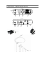
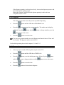
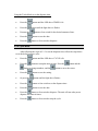
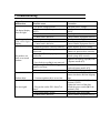
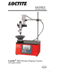
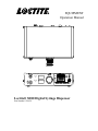
EQUIPMENT Operation Manual SD10 Digital Syringe Dispenser SET SHOT Vacuum psi DISPENSE TEACH Pressure psi EXIT MODE PROGRAM CYCLE TIMER MANUAL Loctite® SD10 Digital Syringe Dispenser Part Number 1514629 TABLE OF CONTENTS 1 Please observe the following.......................................................................................... 3 1.1 Emphasized sections ............................................................................................ 3 1.2 Items Supplied ....................................................................................................... 3 1.3 For your safety ....................................................................................................... 4 1.4 Usage ...................................................................................................................... 4 2 Description - Typical System Set-Up ........................................................................... 5 2.1 Operating Elements .............................................................................................. 6 2.2 Theory of Operation .............................................................................................. 6 3 Technical Data................................................................................................................ 7 3.1 Energy Requirements ........................................................................................... 7 3.1.1 Electrical .............................................................................................................. 7 3.1.2 Pneumatics.......................................................................................................... 7 3.2 Connections and Dimensions.............................................................................. 7 3.3 Other Data .............................................................................................................. 7 4 Installations .................................................................................................................... 8 4.1 Environmental Conditions .................................................................................... 8 4.2 Placement ............................................................................................................... 8 5 Dispensing....................................................................................................................... 8 5.1 Filling the Syringe .................................................................................................. 8 5.2 Set Up...................................................................................................................... 9 5.2.1 Purging Air from the Syringe ............................................................................ 9 5.2.2 Manual Mode ...................................................................................................... 9 5.2.3 Programs ........................................................................................................... 10 5.2.4 Timer mode ....................................................................................................... 10 5.2.5 Cycle Mode ....................................................................................................... 11 6 Cares and Maintenance............................................................................................... 12 6.1 Care ....................................................................................................................... 12 6.2 Maintenance ......................................................................................................... 12 7 Troubleshooting ........................................................................................................... 13 8 Replacement Parts and Accessories ........................................................................... 14 9 Warranty ...................................................................................................................... 14 1 Please observe the following 1.1 Emphasized sections Danger! Refers to safety regulations and required safety measures that protect the equipment, operator, or other persons from injury. Caution! Emphasizes what must be done or avoided so that the unit or other property shall not to be damaged. Notice Gives recommendations for better handling of the unit during operation or adjustment, as well as for service activities. The numbers printed in bold in the text (xx) refer to the corresponding position numbers in the illustration in Section 2 & 2.1. As a result of technical development, the illustrations and descriptions in this instruction manual can deviate in detail from the actual unit delivered. 1.2 Items Supplied 1 SD10 Digital Syringe Dispenser 1 Foot switch 1 User manual 1 Power Supply 1 Syringe Barrel Stand 1 30/55 cc Syringe Air Line Adapter 1 Syringe Test Kit 1.3 For your safety For safe and successful operation of the unit, read these instructions completely. If the instructions are not observed, the manufacturer can assume no responsibility. Damage to the power cord or the housing can result in live voltage. Check the power cord and the unit before each use. If the power cord or the unit is damaged, do not operate! Replace a damaged power cord with a new one. The unit may be opened and repaired only by an authorized Henkel service representative. Improper handling of Loctite® brand products may be hazardous to ones health! Observe general safety regulations for the handling of chemicals! Observe manufacturer’s instructions! Request a safety data sheet for the product used! Always wear goggles, when operating with pressurized air! 1.4 Usage The Loctite® SD10 Digital Syringe Dispenser (1514629) is a self-contained dispenser system and suitable for the precise application of Loctite® brand products at manual workstations such as in workshops, laboratories and industrial installations. It is designed for a small volume applications of Loctite® brand anaerobic, UV curing and gel cyanoacrylate adhesives as well as Loctite® brand chipbonder® adhesives or soldering flux. 2 Description - Typical System Set-Up Front Panel SD10 Digital Syringe Dispenser SET SHOT 4 DISPENSE Vacuum psi TEACH Pressure psi EXIT MODE PROGRAM 5 3 CYCLE TIMER 2 MANUAL 1 Rear Panel Power Input Power Switch 24VDC Output Foot Switch XS-1 Air Input For Service, Spare Parts, & Repairs USA - (1) 860-571-5174 Germany - (49) 89-9268-0 Singapore - (65) 6266-0100 China - (86) 21-2891-8547 24VDC 0.5mA~ MADE IN TAIWAN Visit: equipment.loctite.com L abel P/N: 988341 9 8 7 Air Exhaust SD10 Digital Syringe Dispenser IDH# 1514629 6 2.1 Operating Elements 1 2 3 4 5 6 7 8 9 10 11 12 13 14 Control panel Adjustable air regulator Digital air output/vacuum display Suck back regulator Air output for syringe air line adapter Air input XS-1, foot switch connector Power switch Power input (24VDC) Foot switch Power supply Syringe air line adapter Syringe end cap Syringe piston The syringe piston ensures emptying of the syringe barrel and prevents air from permeating the product as well as preventing the product from running back out of the syringe barrel and into the control unit. 15 Syringe barrel 16 Luer lock tip cap 17 Dispense needle 2.2 Theory of Operation The Loctite® SD10 Digital Syringe Dispenser (1514629) is connected to an external pneumatic supply. The control unit of the SD10 Digital Syringe Dispenser regulates the dispensing pressure and dispense time in order to dispense a repeatable volume of product. The built-in vacuum regulator prevents dripping of the product during pauses in dispensing. 3 Technical Data 3.1 Energy Requirements 3.1.1 Electrical Power supply Power consumption Internal control voltages 110 –240 VAC; 50 –60 Hz Approx. 40 W 5 VDC; 24 VDC 3.1.2 Pneumatics Pneumatic supply Quality If the required quality is not achieved, install a Loctite® brand filter regulator. Range of the Pressure regulator Pressure indicator 3.2 Connections and Dimensions Power connection Pneumatic hose size Dimensions W x H x D: 3.3 Other Data Protection level Operating temperature Storage temperature Weight Continuous sound pressure level min. 2 bar (29 psi); max. 12 bar (174 psi) Filtered 10 μm, oil-free, non-condensing Accessory Order No. 985397 0.00 –7.00 bar (0.00 –100 psi) 0.00 –7.00 bar (0.00 –100 psi) Cold appliance coupl. IEC 320 acc. to VDE 0625 External dia. - 6 mm or 1/4" 265mm W x 211mm D x 72mm H 10.4" W x 8.3" D x 2.8" H IP 33 +10 °C to +40 °C (+50 °F to +104 °F) -10 °C to +60 °C (+14 °F to +140 °F) 3.0 kg (6.6 lbs) < 65 dB(A) 4 Installations 4.1 Environmental Conditions – – No condensing humidity No splashing water 4.2 Placement When the syringe piston is missing and the syringe is handled in an improper manner, the product can enter and contaminate the dispenser. Place the control unit in an elevated position above the syringe! Do not hold the syringe (15) in an elevated position above the dispenser or with the tip pointing upward! In work pauses, press the hose clamp closed on the syringe air line adapter! Hold the syringe correctly for uniform application of the product! When setting the vacuum, start with the vacuum in the full off position and increase slowly to ensure product is not sucked back into the unit. 5 Dispensing 5.1 Filling the Syringe Improper handling of Loctite® brand products may be harmful to ones health! Observe general safety regulations for the handling of chemicals! Observe manufacturer’s instructions! Request a material safety data sheet for the product used! Close the tip of the syringe with the luer lock tip cap. Hold the syringe at an angle to prevent air bubbles during filling. Slowly add product into the syringe. Insert the syringe piston into the syringe barrel. Depending on the dispensing task, fill several syringes at the same time. Store filled syringes with syringe piston, luer lock tip and syringe end caps in place. 5.2 Set Up 5.2.1 Purging Air from the Syringe To avoid air bubbles during dispensing, the tip of the syringe must be purged of air. Hold the syringe over a container since product will flow out! Press the power switch to the position I (ON). Using the pressure regulator (2), set the dispensing pressure to 0.50 bar (approx. 7.00 psi).The set dispense pressure will show on the digital display. Press the Press and hold the button (or foot switch) until the product flows free of bubbles from the dispense needle If the product drips out of the dispense needle: Slowly turn the vacuum regulator (4) counter clockwise until the dripping stops. button until the display reads MANUAL. Do not continue turning after the dripping has stopped. When air is sucked in, the syringe must again be purged of air and curing of the product can occur! This can also cause the product to be sucked back into the unit and will damage it. 5.2.2 Manual Mode This mode gives the operator full control of each dispense cycle. Press the button until the display reads MANUAL. Using the pressure regulator (2), set the dispensing pressure to 0.50 bar (approx. 7 psi). Press and hold the is achieved. button (or foot switch) until the desired dispense quantity If the dispense quantity is achieved too slowly, increase the dispense pressure and check the dispense quantity again. Repeat this sequence until the desired dispense quantity is achieved in an acceptable amount of time. 5.2.3 Programs This mode of operation is used for precise repeatable dispensing. Press the button until the LED above PROGRAM is lit. Press the button to setup the program number. The number on the display will flash. Press the button and the button to change numbers, press the button to move the cursor. Press the button to save the data. You can set a program number to record dispense and interval time in Timer and Cycle mode. The program number can be 00-39. For detailed operation please check chapters 5.2.4 and 5.2.5. 5.2.4 Timer mode Select a program number following the setup in section 5.2.3. Press the button until the LED above TIMER is lit. Press the button, to set the the dispense time, followed by the and the button to change numbers, and the Press the button to save the data. Press the button or foot switch to dispense. button button to move the cursor. Using the Teach Mode to set the dispense time. Press the Press the Pressure the Press the button to save the data. Press the button or foot switch to dispense. button until the LED above TIMER is lit. button until the light above it flashes. button or foot switch for the desired amount of time. 5.2.5 Cycle Mode After following the steps in 5.2.3 to set the dispense time, follow the steps below to set the delay between cycles. Press the button until the LED above CYCLE is lit. Press the button to setup the interval time. Press the button to change numbers, and the button and the button to move the cursor. Press the Or press the Press the button or foot switch to set the dispense time. Press the button to save the data. Press the button or foot switch to dispense. The unit will run at the preset dispense and interval times. Press the button to save the setting. button until the light above flashes. button or foot switch to stop the cycle. 6 Cares and Maintenance 6.1 Care Occasionally the o-ring of the syringe adaptor (12) should be lubricated with silicone grease. This will prolong the life of the o-ring. Clean hands after application of grease to assure surfaces to be bonded are clean. Otherwise bonding might fail. Failure to properly handle cleaning agents may be hazardous to your health! Observe general safety regulations for the handling of chemicals! Observe manufacturer’s instructions! Request a material safety data sheet for the product used! Recommended cleaning agents for: –Anaerobic, UV curing, and Chipbonder® adhesives: There are currently no recommended solvents for removing cured Loctite® brand adhesives. Fluid adhesive residues can be removed with various solvents. ACETONE is well suited for this application. – Cyanoacrylate adhesives: The best solvent is ACETONE for both cured and fluid cyanoacrylates. 6.2 Maintenance The unit requires no special maintenance. 7 Troubleshooting Type of malfunction The digital display does not light. No change in the value on the digital display. No product, too little or too much product. Possible causes –No power voltage present. –Power switch (8) is in position O (OFF). –Power fuse has failed. –Control unit is defective. –No air pressure is present. Correction Check the power voltage. Switch power switch (8) to position I (ON). Check/replace fuse. Contact Henkel Equipment Service. Check pneumatic supply. –Control unit is defective. –Dispense pressure is not set correctly. –Pressure hose is not properly connected. –Syringe (15) is not properly connected. Contact Henkel Equipment Service. Adjust dispense pressure setting. –Luer lock tip cap (16) is not removed. –Dispensing needle (17) is clogged, too small or too large. –Control unit is defective. Product drips. –Vacuum regulator (4) is set too low. No start signal. –Plug on the socket XS1: Start (7) is loose. –Foot switch (10) is defect. –Control unit is defective. Connect air pressure hose correctly. Attach syringe (15) correctly. Replace Luer lock tip cap (16) with a dispense needle (17). Replace dispense needle (17). Contact Henkel Equipment Service. Turn the vacuum regulator (4) counter clockwise until the dripping stops. Switch the power switch (8) to the position O (OFF). Tighten the screws of the plug. Switch the power switch (8) to the position I (ON). Replace the Foot switch (10) Contact Henkel Equipment Service. 8 Replacement Parts and Accessories Description Loctite Item No. 10 ml Clear Syringe Package 97207 30 ml Clear Syringe Package 97244 10 ml Air Line Adapters 97208 30 ml Air Line Adapters 97245 Foot Switch 97201 Filter Regulator 985397 9 Warranty WARRANTY Henkel expressly warrants that all products referred to in this Instruction Manual for (1514629) Henkel SD10 Digital Syringe Dispenser) (hereafter called "Products") shall be free from defects in materials and workmanship. Liability for Henkel shall be limited, as its option, to replacing those Products which are shown to be defective in either materials or workmanship or to credit the purchaser the amount of the purchase price thereof (plus freight and insurance charges paid therefor by the user). The purchaser’s sole and exclusive remedy for breach of warranty shall be such replacement or credit. A claim of defect in materials or workmanship in any Products shall be allowed only when it is submitted in writing within one month after discovery of the defect or after the time the defect should reasonably have been discovered and in any event, within (12) months after the delivery of the Products to the purchaser. This warranty does not apply to perishable items, such as (indicate items: fuses, filters, lights, etc.). No such claim shall be allowed in respect of products which have been neglected or improperly stored, transported, handled, installed, connected, operated, used or maintained. In the event of unauthorized modification of the Products including, where products, parts or attachments for use in connection with the Products are available from Henkel, the use of products, parts or attachments which are not manufactured by Henkel, no claim shall be allowed. No Products shall be returned to Henkel for any reason without prior written approval from Henkel. Products shall be returned freight prepaid, in accordance with instructions from Henkel. NO WARRANTY IS EXTENDED TO ANY EQUIPMENT WHICH HAS BEEN ALTERED, MISUSED, NEGLECTED, OR DAMAGED BY ACCIDENT. EXCEPT FOR THE EXPRESS WARRANTY CONTAINED IN THIS SECTION, HENKEL MAKES NO WARRANTY OF ANY KIND WHATSOEVER, EXPRESS OR IMPLIED, WITH RESPECT TO THE PRODUCTS. ALL WARRANTIES OF MERCHANTABILITY, FITNESS FOR A PARTICULAR PURPOSE, AND OTHER WARRANTIES OF WHATEVER KIND (INCLUDING AGAINST PATENT OR TRADEMARK INFRINGEMENT) ARE HEREBY DISCLAIMED BY HENKEL AND WAIVED BY THE PURCHASER. THIS SECTION SETS FORTH EXCLUSIVELY ALL OF LIABILITY FOR HENKEL TO THE PURCHASER IN CONTRACT, IN TORT OR OTHERWISE IN THE EVENT OF DEFECTIVE PRODUCTS. WITHOUT LIMITATION OF THE FOREGOING, TO THE FULLEST EXTENT POSSIBLE UNDER APPLICABLE LAWS, HENKEL EXPRESSLY DISCLAIMS ANY LIABILITY WHATSOEVER FOR ANY DAMAGES INCURRED DIRECTLY OR INDIRECTLY IN CONNECTION WITH THE SALE OR USE OF, OR OTHERWISE IN CONNECTION WITH, THE PRODUCTS, INCLUDING, WITHOUT LIMITATION, LOSS OF PROFITS AND SPECIAL, INDIRECT OR CONSEQUENTIAL DAMAGES, WHETHER CAUSED BY NEGLIGENCE FROM HENKEL OR OTHERWISE. Henkel Corporation One Henkel Way Rocky Hill, CT 06067-3910 USA Henkel Canada Corporation 2225 Meadowpine Boulevard Mississauga, Ontario L5N 7P2 CANADA Henkel Corporation Automotive/ Metals H.Q. 32100 Stephenson Hwy, Madison Heights 48071 USA Henkel Capital, S.A. de C.V. Calzada de la Viga s/n Fracc. Los Laureles Loc. Tulpetlac, C.P. 55090 Ecatepac de Morelos, MEXICO Henkel Singapore Pte Ltd 401, Commonwealth Drive #03-01/02 Haw Par Technocentre SINGAPORE 149598 Henkel (China) Company Ltd. No. 928 Zhang Heng Road, Zhangjiang, Hi-Tech Park, Pudong, Shanghai, China 201203 Henkel Loctite Korea 8F, Mapo Tower, 418, Mapo-dong, Mapo-gu, Seoul, 121-734, KOREA Henkel Japan Ltd. 27-7 Shin Isogo-cho, Isogo-ku Yokohama, 235-0017 JAPAN www.equipment.loctite.com Loctite is a trademark of Henkel Corporation, U.S.A. © Copyright 2006. Henkel Corporation Teflon is a registered trademark of E.I. DuPont de Nemours Co., Inc. All rights reserved. Data in this operation manual is subject to change without notice. Manual P/N: 8903234 Date: 03/01/2012