1
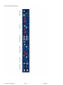
User Manual Neve 8801 Channel Strip 527–358 Issue 2 !!!Please read – includes important safety instructions!!! © 2007 AMS Neve Ltd own the copyright of all information and drawings contained in this manual which are not to be copied or reproduced by any means or disclosed in part or whole to any third party without written permission. As part of our policy of continual product improvement, we reserve the right to alter specifications without notice but with due regard to all current legislation. Disclaimer: The information in this manual has been carefully checked and is believed to be accurate at the time of publication. However, no responsibility is taken by us for inaccuracies, errors or omissions nor any liability assumed for any loss or damage resulting either directly or indirectly from use of the information contained within it. Trademarks: All trademarks are the property of their respective owners and are hereby acknowledged. AMS NEVE LTD BILLINGTON ROAD • BURNLEY LANCS • BB11 5UB • ENGLAND PHONE +44 (0)1282 457011 FAX +44 (0)1282 417282 [email protected] www.ams-neve.com www.neve.eu Neve 8801 User Manual Page 1 02/04/07 Safety Notice For your own safety and for the protection of others please observe the following safety instructions: • Read these instructions • Keep these instructions • Heed all safety warnings • Do not use near water • Clean only with a dry cloth • Do not install near heat sources • Do not block ventilation openings • Protect the power cord • Only use accessories specified by the manufacturer • Unplug during storms, or when unused for long periods • Refer all servicing to qualified personnel only Neve 8801 User Manual Page 2 02/04/07 Index 1. 2. 3. 4. 5. 6. 7. 8. 9. Introduction …………………………………………………………………………………………….… Package Contents …………………………………………………………………………………….…… System Requirements ……………………………………………………………………………………… Brief Description and Characteristics ………………………………………………….………………..… Front Panel Controls ………………………………………………………………………………....…… On/Off Switch ………………………………………………………………………………………..…… Input section ……………………………………………………………………………………………….. Filters Section ………………………………………………………………………………………...…… Dynamics Section ……………………………………………………………………………………..…… 9.1 Sidechain ………………………………………………………………………………………………. 9.2 Limiter/Compressor ………………………………………………………………………………..… 9.3 Expander/Gate ………………………………………………………………………………….….… 10. EQ Section …………………………………………………………………………………….……….. 11. Insert ………………………………………………………………………………………………..….. 12. Audio Router ……………………………………………………………………………………..…….. 12.1 Determining the current signal path ………………………………………………………………….. 12.2 Setting the order of the Channel path ………………………………………………………………… 13. Output Section …………………………………………………………………………………………… 14. Overload …………………………………………………………………………………………………. 15. Rear Panel ……………………………………………………………………………………………….. 16. Optional Digital add-on Board …………………………………………………………….…………….. 16.1 Analogue to Digital Converter ………………………………………………………………………. 16.2 Genie ………………………………………………………………………………………………… 16.3 Optional Board installation procedure ………………………………………………………………. 17. Performance Specifications ……………………………………………………………………………… 18. Block Diagram …………………………………………………………………………………………… 19. Recall Software ………………………………………………………………………………………….. 20. Appendix A ……………………………………………………………………………………………… Neve 8801 User Manual Page 3 02/04/07 4 4 4 4 5 6 6 7 7 8 8 9 10 11 11 11 11 12 12 13 15 15 16 16 17 18 19 20 1. Introduction Thank you for choosing the Neve 8801. This unique channel strip is based on the channel strip featured in the world renowned 88R mixing desk. It contains the highest quality Mic/Line/Instrument Preamp, Dynamics processing, EQ and Insert. The Audio Router function provides a user configurable signal path allowing any order of Dynamics, EQ, and Insert within the channel path. In addition, the EQ and or filters can be placed in the Dynamics sidechain. The configuration of the unit can be stored and recalled via the Neve Recall software on PC or Mac. Up to sixteen 88 series units may be connected to a Recall system simultaneously. 2. Package Contents Please check that your 8801 package contains each of the following: • 8801 unit • External power supply • Power lead • User Manual CD 3. System Requirements The 8801 may be used stand alone. If you wish to use the Neve Recall software to store and reload user configurations you must have a PC (Windows 2000 or later) or Mac (OS10.3 or later) with an available USB port. 4. Brief Description and Characteristics • • • • • • • • • • • • • • • • • • • • • • • High quality transformer coupled Microphone preamplifier identical to that used on the 88R with 0dB to 70dB of gain Switchable Phantom Power 20dB Pad on Microphone and DI inputs Line input with -24dB to +24dB of gain High impedance DI input Optional Digital Genie input and output (CobraNet™ compatible) Phase inversion switch Overload indication at each gain stage High Pass and Low Pass filters switchable between channel path and Dynamics sidechain Dynamics processing based on 88R circuitry Compression/Limiting with auto release Gate/Expander/Ducker Dynamics Sidechain linkable to other 8801 units Key input Compressor and Gate gain reduction meters Balanced switchable Insert 4 band EQ based on the 88R console switchable between channel path and Dynamics sidechain User definable channel path through Dynamics/Insert/EQ using Audio Router function Line output with +10dB of gain control Headphone output Optional Digital Output Cards (AES/EBU/DSD or Genie) User recall/store current state via Neve Recall software USB link to PC or Mac Neve 8801 User Manual Page 4 02/04/07 5. Front Panel Controls Neve 8801 User Manual Page 5 02/04/07 6. On/Off Switch The Neve Logo Switch on the right hand side of the unit switches the unit on and off. 7. Input Section On power up, the default input is the Line input The input selected is shown by the LEDs above the gain knob and is selected by pressing the I/P GAIN knob. Line Input: The line input is accessible via the combo connector (¼’’ Jack and XLR in parallel) on the rear of the unit. It accommodates both balanced and unbalanced input signals. The gain is variable from -24dB to +24dB using the I/P GAIN knob on the front panel. Mic Input: The Mic input uses the XLR input of the combo connector on the front panel. Gain is variable from +20dB to +70dB using the I/P GAIN knob. Mic input is also available on the rear panel. Both the front and rear connectors are wired in parallel. PAD: The PAD button provides 20dB of attenuation on Mic and DI inputs. Phantom Power: The +48V button enables phantom power on the Mic input. DI Input: The DI input uses the ¼’’ jack input of the combo connector on the front panel. The input uses a high impedance instrumentation amplifier (>750kΩ). It accommodates both balanced and unbalanced inputs. Gain is variable from -24dB to +24dB using the I/P GAIN knob. When PAD is switched on the input impedance changes to 100kΩ. DI input is also available on the rear panel. Both the front and rear connectors are wired in parallel. Genie Input: The Genie input is a CobraNet™ compatible input. It is available via an optional daughter card. The input is only selectable when the option card is fitted. See section 15.2 for further details. Phase Button: All inputs can be phase reversed using the PHASE button. PHASE button illuminated indicates a phase inversion between input and output. Neve 8801 User Manual Page 6 02/04/07 8. Filters Section High Pass Filter: The high pass filter has a 12dB per octave (20dB per decade) slope and a frequency range from 30Hz to 300Hz. It is switched into circuit by pressing the High Pass frequency knob. The associated LED lights to indicate activation. Low Pass Filter: The low pass filter has a 12dB per octave (20dB per decade) slope and a frequency range from 1.5kHz to 18kHz. It is switched into circuit by pressing the Low Pass frequency knob. The associated LED lights to indicate activation. Filters to Sidechain: The FILTERS TO SIDECHAIN button puts both filters in the sidechain. When the filters are in the sidechain they are not available in the channel path and vice versa. 9. Dynamics Section Full limiter/compressor and gate/expander facilities are available. The compressor/limiter uses the top row of controls and the expander/gate uses the bottom row of controls. Dynamics Button: The Dynamics button activates the Dynamics section. When illuminated, both Compressor/Limiter and Expander/Gate functions are in circuit. When not illuminated both are bypassed. If you only require one function: • To disable the Compressor set the Threshold to +20dBu and the Ratio to 1 • To disable the Gate set the Range to 0dB Neve 8801 User Manual Page 7 02/04/07 9.1 Dynamics Sidechain The dynamics sidechain is the control signal for the dynamics processing. By default the sidechain receives the signal picked up just at the input of the Dynamics gain stage. The Filters and EQ can be moved to the sidechain path by pushing the FILTERS TO SIDECHAIN and EQ TO SIDECHAIN buttons respectively. When in the sidechain the Filters and EQ don’t act on the channel path. When KEY INPUT is enabled (by pressing the Gate THRESHOLD knob) the sidechain receives the signal from the Key input located on the rear panel. 9.2 Limiter/Compressor The limiter/compressor has knobs for: • Up to 30dB of gain make-up o Pressing on Gain Make up knob toggles Hard and Soft Knee • Threshold range of -30dB to +20dB o Pressing on Threshold knob selects LINK • Ratio of 1:1 to limiting o Pressing on Ratio knob toggles Normal and Fast Attack time • Release times from 30ms to 3s o Pressing on Release knob toggles between Release and Auto Release Knee: The compressor has soft knee characteristics as default with hard knee available by pressing the GAIN MAKE UP knob. Link: LINK can be selected by pressing on the THRESHOLD knob. When enabled, the compressor section of the unit can be controlled by the sidechain of other linked 8801 units. For example, this allows a stereo input across two modules to be compressed by to the same amount, maintaining the stereo image. There is no Master/Slave relationship, the priority is such that the strongest signal always wins. Multiple units can be linked together using the mono ¼” jack socket on the back panel. Attack Time: Pressing on the RATIO knob toggles between Normal and Fast Attack time. Two jumpers inside the unit (see diagram) allow for two variations of attack times. Default Position: - Normal Attack time: 8ms - Fast Attack time: 2ms Alternative Position: - Normal Attack time: 3ms - Fast Attack time: 0.5ms Auto Release: Pressing on the RELEASE knob switches to Auto Release - a triple time-constant, programme dependent release time. Anti pumping and breathing circuitry allows the unit to operate on the source musically whilst retaining absolute control over the dynamic range. Gain Reduction: The red meter indicates the gain reduction in dB applied by the compressor. Neve 8801 User Manual Page 8 02/04/07 9.3 Expander/Gate The expander/gate has knobs for: • Hysteresis variable from 0dB to 25dB o Pressing Hysteresis knob selects Expander mode • Threshold variable from –30dBu to +20dBu o Pressing Threshold knob selects Key input • Range variable from 0dB to 60dB o Pressing Range knob toggles Normal (0.5ms) / Fast (0.05ms) Attack time • Release time: 10ms to 3s o Pressing Release knob selects Invert (Ducker) Key Input: Key input is selectable by pressing on the THRESHOLD knob (Key input is on Combo connector with XLR and JACK in parallel) located on the back panel. When enabled the sidechain uses the Key Input signal rather than the signal picked up just at the input of the Dynamics gain stage as the control signal for the Dynamics processing. Hysteresis: The HYSTERESIS knob sets the difference in threshold for signals that are rising or falling in level. Signals that are rising in level turn on when the level reaches the threshold level plus the hysteresis value. Signals that are falling in level turn off at the lower threshold level. Raising the threshold for rising signals prevents noise turning the gate on, while allowing a lower threshold for falling signals to prevent reverb signal ‘tail’s being prematurely gated. For example, if the threshold is set at -30 and the hysteresis is set at 10, the signal level would have to rise above -20dB before the channel turns on and the channel would remain on until the signal level fell below -30dB. The knob allows up to 25dB of hysteresis. Expander: Pressing the HYSTERESIS knob switches the gate off and the 2:1 expander on. The EXPANDER LED lights to indicate Expander mode. Invert/Ducker: Pressing the RELEASE knob inverts the behaviour of the Gate. The function is sometimes call a “ducker”. The INVERT LED lights to indicate that the Gate is in Invert mode. This feature is normally used with an external Key input. When gating, a signal above threshold level on the key input allows signal to pass; when ducking a signal above threshold level on the key input causes the gain of the channel signal to be reduced by the amount set on the RANGE knob. Gain Reduction: The green meter indicates the gain reduction in dB of the gate. Neve 8801 User Manual Page 9 02/04/07 10. EQ Section EQ Button: The EQ button activates the EQ section. When illuminated, EQ is in circuit. When not illuminated EQ is bypassed. EQ TO SIDECHAIN Button: The EQ TO SIDECHAIN button places the EQ in the sidechain. Placing the EQ in the sidechain removes it from the channel path and vice versa. Low Frequency Band: • • • • • The LF GAIN knob sets the cut or boost for the low frequency band of the EQ with a range of +/-20dB. Pressing the LF GAIN knob switches the Low Frequency EQ band between Peaking and Shelving modes. An LED lights to indicate when Shelving is selected. The LF Hz knob sets the low frequency between 33Hz and 440Hz. When the LF EQ band is set to Peak, pressing the LF Hz knob switches the band between Low and High Q. An LED lights to indicate the selection of High Q. Low Q is 0.7 and High Q is 2.0. When the LF EQ band is set to Shelving mode, selecting High Q has no effect on the Shelving mode. The High Q LED is therefore deactivated and stays not illuminated. Low Mid Frequency Band: • • • The LO MID GAIN knob sets the cut or boost for the low medium frequency band of the EQ with a range of +/20dB. The LMF Hz knob sets the low medium frequency between 120Hz and 2kHz. The LO MID Q knob adjusts the continuously variable Q between 0.4 and 10. High Mid Frequency Band: • • • The HI MID GAIN knob sets the cut or boost for the high medium frequency band of the EQ with a range of +/20dB. The HMF Hz knob sets the high medium frequency between 800Hz and 9kHz. The HI MID Q knob adjusts the continuously variable Q between 0.4 and 10. Neve 8801 User Manual Page 10 02/04/07 High Frequency Band: • • • • • The HF GAIN knob sets the cut or boost for the high frequency band of EQ with a range of +/-20dB. Pressing the HF GAIN knob switches the High Frequency EQ band between Peaking and Shelving modes. An LED lights to indicate when Shelving is selected. The HF Hz knob sets the high frequency between 1.5kHz and 18kHz. When the HF EQ band is set to Peak, pressing the HF Hz knob switches the band between Low and High Q. An LED lights to indicate the selection of High Q. Low Q is 0.7 and High Q is 2.0. When the LF EQ band is set to Shelving mode, selecting High Q has no effect on the Shelving mode. The High Q LED is therefore deactivated and stays not illuminated. 11. Insert Insert button: The INSERT button switches the insert into the channel path. The Insert send and return can be found on the rear of the unit. The send is on a male XLR and the return is on a Combo Connector (XLR and ¼’’ Jack in parallel). The unit supports both balanced and unbalanced send and return. 12. Audio Router The Audio Router button allows the setting and interrogation of the order of Dynamics, EQ and Insert in the channel path. The default order is DYNAMICS → EQ → INSERT 12.1 Determining the current signal path To view the current order of the signal path, press the Audio Router button once. The DYNAMICS, INSERT and EQ buttons will flash in the order they are currently set. If the EQ is in the sidechain, then the EQ TO SIDECHAIN button will flash while EQ button is illuminated. Determining the signal path is a display only and has no impact on the Channel path. 12.2 Setting the order of the Channel path To set a new Channel path order: 1. Enter programming mode by pressing and holding the AUDIO ROUTER button until it begins to flash. 2. Press DYNAMICS, EQ and INSERT buttons in the order you wish them to be arranged in the Channel path. When the third button has been pressed the AUDIO ROUTER button stops flashing, the new order is stored and the Channel path is updated. Then, the unit returns to normal operation. While in programming mode, pressing the AUDIO ROUTER button will cancel the programming mode and return to normal operation. Programming mode will time out after 15 seconds of inactivity and the unit will return to normal operation without changing the order of the signal path. Neve 8801 User Manual Page 11 02/04/07 13. Output Section Line output is from a Male XLR on the back panel and accommodates both balanced and unbalanced connections. The output signal is routed to a headphone amplifier and is accessible on the ¼” Jack socket also on the back panel. The signal level for both the XLR line output and the headphone output is controlled by the O/P Gain knob. The range is from −infinity to +10dB. The gain of the headphone output can be increased by moving an internal jumper (as shown below) Jumper shown in high gain position Bargraph LED Meter: The Vu meter can be set to display the input or the output signal level. Pressing the O/P GAIN knob toggles between input and output monitoring and the current state is indicated by the LED to the left of the O/P GAIN knob. On powering up the unit the meter displays the input level by default. 14. Overload There are many gain stages in the 8801 channel strip. It is possible for any one of these stages to overload. Overloading is indicated by the following means: Indication by button illuminating RED PHASE DYNAMICS INSERT EQ Digital option Input stage or input signal overload Dynamics overload Insert overload EQ overload (detected at each band of EQ) ADC Option Board overload If overloading is occurring at multiple stages only the highest priority indication will be shown. The priority is governed by the signal path of the audio. The input has the highest priority followed by Dynamics/Insert/EQ in the order set by the Audio Router. Neve 8801 User Manual Page 12 02/04/07 15. Rear Panel Rear Panel Audio Connections • Line Input: the line input combo socket accepts input signals from either male XLR or male ¼” Jack connectors. Input signals can be balanced or unbalanced. • Mic Input: The Mic input is on a Female XLR. This input in parallel with the XLR input of the Combo connector of the front panel. • DI Input: The DI input is on a ¼’’ jack input. This input is in parallel with the Jack input of the Combo connector of the front panel. • Key input: the key input is located on a 9 pins D-Type connector on pins 6, 7 and 8. Input signal can be balanced or unbalanced. The key input provides an alternative sidechain signal and is activated by pressing the THRESHOLD knob on the front panel. D-Type pin out 1 – DYNAMICS LINK SIGNAL 2 – DYNAMICS LINK 0V 3 – DYNAMICS LINK SIGNAL 4 – DYNAMICS LINK 0V 5 – NOT CONNECTED 6 – KEY INPUT HI 7 – KEY INPUT LO 8 – KEY INPUT 0V 9 – NOT CONNECTED CASE CONNECTED TO UNIT CHASSIS • Dynamics Sidechain Link: the dynamics side chain link is available on a 9 pins D-Type connector on pins 1-2 and 3-4. Pins 1 and 3 as well as pins 2 and 4 are in parallel. Multiple 8801 units can be linked allowing all linked units to be compressed by the same amount. Multiple units can be linked together by forming a daisy chain of the Dynamics Links. Please find below an example on how to link 3 units. Unit 1 Neve 8801 User Manual Unit 2 Page 13 Unit 3 02/04/07 • Insert: the insert send is on a Male XLR and the return is on a Female XLR connector. The insert can accept a balanced or unbalanced signal. • Line Output: the line output is on a male XLR connector. It can provide balanced and unbalanced output. • Headphone: the headphone output is a on ¼” jack connector. The level of the headphone output is set by the Output Level knob on the front panel. The gain of the headphone output can be increased by changing an internal jumper (see 12.Output section for diagram). As the 8801 Channel Strip is a mono channel unit, the headphone receives the same signal on the Left and Right headphone speakers. Rear Panel Power section • USB: the Type B USB socket is used to connect the 8801 unit to a PC or Mac for Recall store and recall of the unit settings. • Technical Earth Switch: The grounding of the unit can be set to two different points: 1) The Mains earth from the power supply 2) The studio technical earth via the CHASSIS screw on the back of the unit With the switch in the OFF position the chassis of the unit is connected to the Mains earth via the power supply. With the switch in the ON position the chassis of the unit should be connected to the studio technical earth using the CHASSIS screw on the back of the unit. For safety reasons the chassis is NOT disconnected from the main Earth but is connected through a Resistor/Capacitor filter. !!!WARNING!!!! Connections to the technical earth and changes to the unit grounding should only be carried out by qualified personnel. • Fuse: • Power DIN socket: The 8 pin DIN socket should only be used to connect the power supply provided with the 8801 unit. The removable fuse holder houses a 1.6 AT fuse PLEASE NOTE: for technical reasons the orientation of the socket is the opposite way up to normal. The “top” of the DIN connector will therefore be underneath. It is not possible to connect the plug the wrong way up. Neve 8801 User Manual Page 14 02/04/07 16. Optional Digital add-on board The 8801 has an expansion slot allowing access for digital connectivity. Two digital options are available: • Analogue to Digital converter featuring AES/EBU and DSD outputs • Genie Digital Input and Output compatible with CobraNet™ 16.1 Analogue to Digital Converter - AES/EBU (AES 3) & DSD The optional AES/EBU & DSD digital daughter board provides the following connections: • DSD Output • Wordclock Input and Output • SPDIF Output • AES Output • AES Sync Input When the Analogue to Digital converter card is fitted the DIGITAL O/P section on the front of the 8801 is enabled. Sampling Frequency Selection Digital Audio sample frequency can be selected by pressing the DIGITAL O/P button. This will toggle through the sampling frequencies one at a time. The current sampling frequency is indicated by the LEDs beneath the Digital O/P button. Digital Sync The ADC option board has 2 sync inputs, AES 3 on a female XLR and Word Clock on a BNC. • If neither sync input is present, the unit will synchronise to its internal clock. • If either of the sync inputs is present at the sampling frequency displayed on the front panel, the LED (AES or WCLK respectively) will illuminate green showing that the sync input is being used as a reference. • If the incoming sync sample rate differs from the sample rate displayed on the front panel, the WCK or AES LEDs will flash. • If both sync inputs are present and correct the word clock input will be used as the reference and the AES LED will flash. Neve 8801 User Manual Page 15 02/04/07 Double Rate AES Output It is also possible to select 96kHz (or 88.1kHz) sampling rate with a 48kHz (or 44.1kHz) sync input. Similarly it is possible to select 192kHz (or 176.2 kHz) sampling rate with a 96kHz (or 88.1kHz) sync input. This will cause the unit to output double rate AES on the AES Output connector. The sync LED will illuminate green indicating the sync reference is still being used for the digital output even though the ADC is sampling at twice the sync input sampling rate. In this situation AES out carries the odd and even samples of the audio double rate signal on its left and right digital channels respectively. DSD Selecting DSD will default to 44.1kHz reference. If no sync is available it will use its own internal clock. The DSD output is switchable between SDIF 2 and SDIF 3 with a rear panel switch. SDIF2 DSD data requires an external sync clock which is passed to the Digital to Analogue converter of the receiver. Preferably use the 8801 Wordclock O/P clock which is available on the back of the 8801 ADC option. SDIF3 DSD data have embedded clocks and don't require any external sync clock. N.B. Refer to your DSD recording device for compatibility information. Headroom: The unit can be set to one of three headroom settings; +14dB, +18dB or +22dB relative to +4dBu. The headroom is the number of dBs above +4dBu before the ADC clips. The DIGITAL O/P button will illuminate red if the selected input level is exceeded for more than 1 sample. The headroom can be changed by accessing the switches on the back of the ADC optional board. 75 Ohm WCLK: Selects a 75 Ohms input impedance for WCLK in. 16.2 Genie Input/Output The Genie daughter card allows the 8801 to connect to a CobraNet™ network. When installed the Genie input can be selected by pressing the I/P GAIN knob on the front panel. The Genie output is taken in parallel with the Line output of the unit. CobraNet™ allows the transfer of digital audio over a regular Ethernet network through the connection of CobraNet™ compatible devices. To use the Genie input/output you will need a computer with a relevant software for controlling a CobraNet™ network, such as CobraNet™ manager Software. This will allow you to create audio paths using the Ethernet network to connect any CobraNet™ devices. 16.3 Optional Board installation procedure Please refer to Appendix A for installation procedure of both optional boards Neve 8801 User Manual Page 16 02/04/07 17. Performance Specifications Microphone input impedance (balanced): 1.2k Ohms Microphone input headroom: +26dBu (reference 0dBu) Microphone input gain range: 0dB to 70dB (using PAD) Line input impedance (balanced): > 20k Ohms Line input headroom: +26dBu (reference 0dBu) Line input gain range : -24dB to 24dB DI input impedance (balanced): > 750 kOhms DI input headroom: +20dBu (reference 0dBu) DI input gain range: -44dB to +24dB (using PAD) Line output impedance: <50 Ohms Main output Maximum output: > +26dBu into 600 Ohms Frequency Response: +/- 0.2 dB 10Hz to 20 kHz +/- 0.5 dB 10Hz to 40 kHz Line Input to Main Output THD + N: < 0.005% Line Input to Main Output, 20Hz to 20kHz, using a measurement window of 10Hz to 80 kHz Noise: Line Input to Main Output: All the audio blocks in circuit: < -89dBu < -80dBu All noise measurements made between 20Hz and 20kHz using a measurement window of 10 Hz to 22 kHz Dimensions: • • • Width 48.2 cm - 19 inches Height 4.4 cm - 1.75 inches (1U) D epth 24 cm - 9.5 inches (without the power socket plugged in) Weight: Neve 8801 User Manual 3.0 kg – 6.6 lbs. Page 17 02/04/07 18. Block Diagram Neve 8801 User Manual Page 18 02/04/07 19. Recall Software Neve Recall software allows settings from the 8801 to be stored on a PC or Mac and recalled for later use. Recall can be used for all the units in the 88 range including 8801, 8803, 8804 and 8816. Multiple units can be stored and recalled together. Please see the Recall Manual for further details. This may be downloaded from the Neve web site at: http://www.ams-neve.com/html/downloads/index.php Neve 8801 User Manual Page 19 02/04/07 20. Appendix A Neve 8801 User Manual Page 20 02/04/07