1
P45 Series Battery Charger
Operating Manual
Effective: April, 2006
Alpha Technologies
Power
®
P45 Series Charger
Operation Manual
031-186-B1-001, Rev. A
Effective Date: April, 2006
Copyright © 2006
Alpha Technologies, Inc.
member of The
GroupTM
NOTE:
The technical data and specifications in this document provided courtesy of MTI Technologies and have not
been verified by Alpha Technologies.
NOTE:
Photographs contained in this manual are for illustrative purposes only. These photographs may not match
your installation.
NOTE:
Operator is cautioned to review the drawings and illustrations contained in this manual before proceeding. If
there are questions regarding the safe operation of this powering system, please contact Alpha Technologies
or your nearest Alpha representative.
NOTE:
Alpha shall not be held liable for any damage or injury involving its enclosures, power supplies, generators,
batteries, or other hardware if used or operated in any manner or subject to any condition not consistent with
its intended purpose, or is installed or operated in an unapproved manner, or improperly maintained.
Contacting Alpha Technologies: www.alpha.com
or
For general product information and customer service (7 AM to 5 PM, Pacific Time), call
1-800-863-3930
For complete technical support, call
1-800-863-3364
7 AM to 5 PM, Pacific Time and 24/7 emergency support
031-186-B1-001, Rev. A
3
TABLE OF CONTENTS
IMPORTANT SAFETY INSTRUCTIONS ............................................................................................... 5
INTRODUCTION ................................................................................................................................... 9
INSTALLATION.................................................................................................................................... 10
PLACEMENT....................................................................................................................................... 10
VENTILATION AND COOLING ........................................................................................................... 10
ELECTRICAL CONNECTION AND WIRING........................................................................................11
POWER UP ..........................................................................................................................................11
SYSTEM POWER OFF PROCEDURE ................................................................................................11
THEORY OF OPERATION .................................................................................................................. 12
DISPLAY SCREEN AND KEYPAD ...................................................................................................... 13
DISPLAY SCREEN .............................................................................................................................. 13
Keypad: .................................................................................................................................. 13
Fixed charger mode:............................................................................................................... 13
Display unit ............................................................................................................................. 13
ACCESSING MENU VIA KEYPAD; OVERVIEW................................................................................. 14
MENU STRUCTURE QUICK OVERVIEW .......................................................................................... 15
MENU DETAILED FUNCTIONS .......................................................................................................... 18
MAIN MENU ........................................................................................................................................ 18
Equalize .................................................................................................................................. 18
LCD Contrast .......................................................................................................................... 18
Reset alarms and relays (available in case of alarm only) .................................................... 19
Adjust ................................................................................................................................... 19
Control ................................................................................................................................... 19
Alarms ................................................................................................................................... 20
Level 2 (strict level)................................................................................................................. 22
Readings ................................................................................................................................ 23
MODBUS (OPTIONAL) ....................................................................................................................... 24
MATERIAL CONFIGURATION ............................................................................................................ 24
RAM MEMORY MAP ........................................................................................................................... 24
1.1
1.2
1.3
1.4
Format for voltage and current values ............................................................................ 25
Logic of alarms ................................................................................................................. 26
Float/Equalize .................................................................................................................. 26
Reset Alarm...................................................................................................................... 27
TROUBLE SHOOTING ....................................................................................................................... 28
REGULAR PREVENTIVE MAINTENANCE ........................................................................................ 29
CONTROL BOARD (PC) - ADJUSTMENT PROCEDURE .................................................................. 30
EXAMPLE............................................................................................................................... 30
Procedure ............................................................................................................................... 31
ALARMS ADJUSTMENT PROCEDURE ............................................................................................. 32
EXAMPLE............................................................................................................................... 32
Procedure ............................................................................................................................... 32
4
031-186-B1-001, Rev. A
Safety Notes
Review the drawings and illustrations contained in this manual before proceeding. If there are any questions
regarding the safe installation or operation of the system, contact Alpha Technologies or the nearest Alpha
representative. Save this document for future reference.
To reduce the risk of injury or death, and to ensure the continued safe operation of this product, the following
symbols have been placed throughout this manual. Where these symbols appear, use extra care and
attention.
ATTENTION:
The use of ATTENTION indicates specific regulatory/code requirements that may affect the placement of
equipment and /or installation procedures.
NOTE:
A NOTE provides additional information to help complete a specific task or procedure.
CAUTION!
The use of CAUTION indicates safety information intended to PREVENT DAMAGE to material or
equipment.
WARNING!
A WARNING presents safety information to PREVENT INJURY OR DEATH to the
technician or user.
Safety Precautions
•
Only qualified personnel may service the system.
•
Verify the voltage requirements of the equipment to be protected (load), the AC input voltage to the power
supply (line), and the output voltage of the system prior to installation.
•
Verify the utility service panel is equipped with a properly rated circuit breaker for use with this system.
•
When connecting the load, DO NOT exceed the output rating of the power supply.
031-186-B1-001, Rev. A
5
Recycling and Disposal Instructions
Spent or damaged batteries are considered environmentally unsafe. Always recycle used batteries or dispose
of the batteries in accordance with all federal, state and local regulations.
Electrical Safety
•
•
•
•
•
•
•
Lethal voltages are present within the power supply and electrical boxes. Never assume that an electrical
connection or conductor is not energized. Check the circuit with a volt meter with respect to the grounded
portion of the enclosure (both AC and DC) prior to any installation or removal procedure.
Always use the buddy system when working under hazardous conditions.
A licensed electrician is required to install permanently wired equipment.
Input voltages can range up to 600 VAC. Ensure that utility power is disabled before beginning installation
or removal.
Ensure no liquids or wet clothes contact internal components.
Hazardous electrically live parts inside this unit are energized from batteries and capacitors even when
the AC input power is disconnected.
AC and DC currents are present in this system even with the indicators and circuit breakers in the OFF
position.
Mechanical Safety
•
•
•
6
Keep hands and tools clear of fans. Fans (if equipped) are thermostatically controlled and will turn on
automatically.
Power supplies can reach extreme temperatures under load.
Use caution around sheet metal components and sharp edges.
031-186-B1-001, Rev. A
Introduction
Thank you for having chosen Alpha Industrial Power. The P45 series battery charger is designed to
provide quality DC power for many years.
This user’s manual contains important technical instructions to be followed by qualified personnel
responsible for the installation, start-up and maintenance of this unit. We recommend that this
manual be read closely to ensure safe and reliable operation of this equipment.
NOTE:
Upon receipt, inspect the unit for shipping damage. Verify any wire connections have not become loose or
disconnected during transportation. Do not install unit until receiving inspection has been completed.
Installation
Placement:
FOR INSTALLATION, PLEASE REFER TO NATIONAL AND LOCAL ELECTRICAL CODES.
The system is very heavy equipment. To prevent personal injury or equipment damage, use lifts
and extreme care when handling.
Ventilation and cooling:
The rectifier/charger is rated to better perform within 14°F (–10°C) and 122°F (+50°C) temperature
range.
To calculate the required air displacement (exchange) volume, please use the following equation:
V = BTU x e (0.125 x H x Tk/To) / (Tr -Tk)
V = air flow: [cubic meter/hour]
BTU = Total dissipated heat
Tr = Maximum allowed room temperature [°K] {i.e. 50°C = 323°K]
Tk = Temperature of input cooling air
To = 273°K
H = Altitude [km]
Avoid placing the system in direct sunlight.
NOTE:
To ensure adequate ventilation and safe access make sure that the following clearances are respected:
•
•
3 in. (10 cm) on the sides and top
3 feet (1 meter) in front of the unit.
Should seismic conditions require a more secure installation the unit may be bolted to the floor. Four (4) holes
are provided for this purpose.
031-186-B1-001, Rev. A
7
Installation, continued
Electrical connection and wiring
Before Connecting the P45 battery charger verify the following:
•
•
•
•
The battery breaker is disconnected (if applicable)
All the circuit breakers are OFF
The relays, fuses and circuit boards are installed
The unit is wired in accordance with the instructions (refer to the wiring connections
and electrical diagram)
Wire size is very important. The nameplate provides the essential information regarding the input and
output voltages and currents.
Refer to your Local or National Electrical Code (NEC) for WIRE GAUGE and GROUNDING
instructions.
NOTE:
Use appropriate gauge wire for current load.
Correct voltage and polarity are of critical importance. Check all connections for tightness and
polarity.
When connecting batteries, observe correct polarities.
Power up
After all wire installation has been completed and double checked, the unit may be powered up as
follows:
•
•
•
•
•
•
•
•
•
Before connecting the load to the charger, compare the critical characteristics
of the load with the critical characteristics of the charger (i.e. measure lineneutral voltage, positive-neutral voltage).
Keep a log of manipulations (i.e. VFLOAT and VEQUALIZE values entered,
alarm messages, alarm and SCR blinking LEDs).
All input and output breakers must be in OFF position.
Apply power to the equipment from the source panel.
Turn on AC breaker (ON position).
Turn on DC breaker (if supplied) (ON position).
Green LED must turn ON.
Wait 5 seconds until the indication screen (LCD) indicates the system output
voltage and status.
The system soft starts by increasing the output current and the voltage.
If readings or calibration of the unit is necessary, refer to the field programming section for more
information.
System power Off procedure
•
•
•
•
Open the AC breaker (OFF position).
Open the DC breaker (if supplied) (OFF position).
Open the source panel’s AC breaker (OFF position).
If work inside the unit has to be performed, wait 5 minutes to discharge the filter capacitors or
use bleeding resistors of the correct rating to discharge the capacitors.
Upon completion of this procedure, the system can be considered de-energized.
8
031-186-B1-001, Rev. A
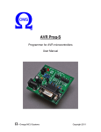
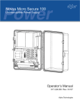
Theory of operation
CONTROL BOARD PC20
DISPLAY
MODE F L t
Eq
Ok
Exi t
SEQUENTIAL
ACCESS MSG
ALARMS
MANUAL
INPUT
A
B
C
D
I/P
V REG
MONITORING
A LIMIT
V
O/P
A
MONITORING
AC
DC
IN
OUT
V
V
t
t
T1
SCR
+
V
t
L1
SHUNT
F1
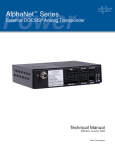
T1 — The AC supply is transformed and isolated.
SCR — The transformer secondary voltage is rectified by a full-wave, half-controlled bridge.
L1, C1 (optional) — The rectified DC voltage is smoothed by LC filter section.
Shunt — Current and voltage reading sent to the control board
F1 — A fuse protects the SCRs and diodes.
Control Board — The PC20 series control board provides automatic charge control, precise voltage
regulation, alarm status annunciation and display.
031-186-B1-001, Rev. A
9
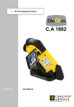
Display Screen and Keypad
Display Screen
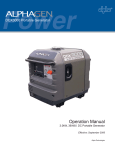
The P45 series provides a very flexible and friendly user interface. The display supplied with the
standard unit’s features a high visibility, back light LCD display.
Keypad
The P4500 uses four (4) long life membrane switches.
Equalize mode
or other message
described in this
manual
To Choose
Float mode
or other
message
described in
this manual
MODE
OK
FLT
A
B
Eq
Exit
C
AC On
Alarms Active
D
Each Key corresponds to a function
Fixed charger mode
Display unit
• Adjustable values are displayed on the higher row of the LCD, i.e. number of relays, alarm ON/OFF,
voltage level.
• Key functions are displayed on the lower row, depending of the menu context.
• When an alarm is active on the charger the exact failure message is appears and the red LED blinks to
warn the user.
• In case of multiple alarms the P45 display unit will show sequentially all the warning messages.
• There is also an AC sector detection LED (green LED).
• The user is able to save parameters individually.
• LCD power save feature shuts down the display unit after 5 minutes of keyboard inactivity. When the
P45 enters power save mode it saves the latest values entered. Upon wake-up, the P45 returns to
the main menu.
• The display accuracy is ± 2%, ± 1 digit.
10
031-186-B1-001, Rev. A
Accessing menu via keypad; overview
On power-up the following reading appears on the screen (example).
131.4V
Equalize
A
0.0A
B
C
D
From that point, if you press any key, A to D (only once), you reach the menu screen.
MODE
OK
FLT
A
B
Eq
Exit
C
D
Press A (OK), to access tthe Float / Equalize menu. Press D (Exit) to step back to the menu screen.
From the menu, you may reach the different functions by pressing B(
MODE
OK
A
031-186-B1-001, Rev. A
FLT
B
).
Eq
Exit
C
D
11
…after one touch of the B (
) key, you get the first function “Adjust”.
ADJUST?
OK
A
Continuing pressing B (
B
Exit
C
D
) will make the screen successively scroll through the following functions:
Reset Alarm ? (present only in case of alarm)
Adjust?
Reading?
Relay test?
Contrast LCD
Pressing C (
screen.
), 4 times, will make the screen scroll in the opposite direction, back to the initial menu
MODE
OK
A
FLT
B
Eq
Exit
C
D
Each function has many sub-functions represented by the following tree structure.
12
031-186-B1-001, Rev. A
Menu structure quick overview
(some of the menu items may be not applicable for your order)
From the previous menu screen, press B
B(
)
Reset Alarm?
B(
)
Adjust?
(visible only in case of alarm)
A (Ok)
Enter Password (contact AIP for password of this level 2 access)
WARNING!
Modifications to the following settings affect output voltage and output current of the
charger and should be done only by qualified technician.
…Control?
A (Ok)
Float
B(
) I Lim
124.9
(for example)
23.3A
Eq
131.5
TEQ
08 H
LVEQ
106.1V
TALimEq
05mn
AC Eq
T Float
30 D
( * ) available only if Eq is “On”
B(
031-186-B1-001, Rev. A
) ...Alarm?
A (Ok)
Talarm
B(
) HVAL
…
HVSH
L VAL
L Vdis
GNDFGNDF+
AC Fail
LCD latch
Com Al latch
Ind Al latch
Audio Alarm
Mesg latch
Rct. fail
Htemp
H Ext T
L Ext T
ACHV
ACLV
Fuse
Hi ripple
I lim Alarm
Eq Alarm
Bat. disch
On
On
On
On
*
*
*
*
*
10 S (for example)
138.1V
On
90.2V
Off
100.0V
On
61.5V
On
5.0mA
Off
5.0mA
Off
On
Off
Off
Off
Off
Off
On
Off
100C
Off
00C
Off
160.0V
Off
0.0V
Off
Off
Off
Off
Off
Off
13
Pressing C( ) repetitively will make you scroll back in the menu. Pressing D(Exit) will make you
step one level back in the hierarchy of the tree menu.
B(
) ……………
Level2?
A (Ok)
Enter Password (contact AIP for password of this level 2 access)
WARNING!
Modifications to the following settings should be done by qualified technician)
B(
…
Display Off
) Default value
Nom Volt
Nom AMP
DCV cal
DCA cal
AC display
ACV cal
ACA cal
VMIN
VMAX
IMAX
Remote V sens
Load sharing
Tcomp
LCD Pwr save
Remote EQ
AH display
Batt capa
Off
(for example)
150V
25 A
132.0V
0.0A
Off
78.4V
539.5A
0.0V
160.0V
*02.2A
Off
Off
Off
Off
Off
Off
100AH
*
*
( * ) affect menu option in Reading submenu if set to “ON”
Pressing C( ) repetitively will make you scroll back in the menu. Pressing D(Exit) will make you step one
level back in the hierarchy of the tree menu.
B(
)
Reading?
A (Ok) : ……Frequency
B( ) AC display
*
…
AH meter
*
(not yet available)
( * ) : must be set “ON” in Level2 menu, to be visible here
B(
)
Relay test?
A (OK)
A(Yes)
D(No)
Contrast LCD
Press A (OK)
A(Set)
D(No)
B(
14
)
031-186-B1-001, Rev. A
MENU DETAILED FUNCTIONS
(some of the menu items may be not applicable for your order)
Definition of the 4 keys functions. Display field explains the key function shown on the LCD lower row
depending on sub-menu context.
KEY
ACTION
DISPLAY
A
“OK” Key
OK
B
Scroll Down sub-menu
C
Scroll Up sub-menu
D
Return to previous menu
NOTE
Enter the displayed
sub-menu
(or Set key for sub-function)
Go UP next
selection
Go DOWN last
selection
Exit
Return last selection
Main menu:
Use
or
keys to scroll the level 0 sub-menus. SET to enter menu.
Equalize
DISPLAY
Float Equalize Exit
PRESS
Float
Set float mode
Equalize
Set Equalize mode
Exit
Return to main menu
DISPLAY
Reading
ACTION
PRESS
SET
ACTION
Display frequency,AC diaplay, AH meter
LCD Contrast
DISPLAY
Contrast LCD
031-186-B1-001, Rev. A
PRESS
SET
+
–
ACTION
Access contrast control
Contrast High
Contrast Low
15
Reset alarms and relays: (available in case of alarm only)
DISPLAY
PRESS
ACTION
Reset relays
Yes
No
Reset all the relays
Go to Reset alarm
Reset Alarm msg
(not displayed)
Yes
No
Clear all alarms messages
Go to Relay test
Relay Test
(not displayed)
Yes
No
Test all relays
Go back one level
Adjust:
Use
or
keys to scroll the sub-menus. SET to enter menu. EXIT to return to previous menu.
DISPLAY
PRESS
ACTION
PASSWORD
B–A–C (Push in order)
EXIT
Enter Level 1
Return to previous menu
Password must be valid to access
Control, Alarms and reading submenu
Control?
SET
Go to Control adjustments
Alarms?
SET
Go to alarm adjustments
Level2?
SET
Go to level 2sub-menu
Control:
Use
menu.
or
DISPLAY
16
keys to scroll to the Control sub-menus. SET to enter menu. EXIT to return to previous
PRESS
ACTION
DEFAULT VALUE
Float
+ or -
Adjust Float Voltage (V)
Vnom x 1.09
I LIM
+ or -
Adjust Current Limit (A)
Eq
SET
+ or -
Toggle On/Off Equalization Voltage
Adjust Equalization Voltage
T eq
+ or -
Adjust Equalization Time (Hour)
L VEQ
+ or -
Adjust Low Equalization Voltage (V)
Vfloat x 0.85
TA LIM E
+ or -
Adjust Time/Current Limit Equalization (Minute)
5 min
ACEq
SET
Toggle On/Off AC Equalization
On
Tfloat
+ or -
Adjust Float Timing (Days)
28
On
Vnom x 1.12
031-186-B1-001, Rev. A
Alarms
Use
or
keys to scroll the Alarm sub-menus. SET to enter menu. EXIT to return to previous menu.
DISPLAY
Talarm
PRESS
ACTION
DEFAULT VALUE
+ or –
Adjust alarm Timing (sec)
10 sec
+ or –
Adjust High Voltage alarm level (V)
Veq x 1.05
NEXT
Go to Relays selection/toggle menu
NEXT, On/Off
Toggle On/Off High Voltage alarm
On
NEXT, + or –
Select relays number (1 to 7)
No. 2
+ or –
Adjust High Voltage Shutdown level (V)
Veq x 1.1
NEXT
Go to Relays selection/toggle menu
NEXT, On/Off
Toggle High voltage shutdown
Off
NEXT, + or –
Select relays number (1 to 7)
No. 8
+ or –
Adjust Low Voltage alarm level (V)
0.8 x Vfloat
NEXT
Go to Relays selection/toggle menu
NEXT, On/Off
Toggle On/Off Low Voltage alarm
On
NEXT, + or –
Select relays number (1 to 7)
No.3
+ or –
NEXT
NEXT, On/Off
NEXT, + or –
Adjust Low Voltage Disconnect level (V)
Go to Relays selection/toggle menu
Toggle Low voltage Disconnect
Select relays number (1 to 7)
No. 4
+ or –
NEXT
NEXT, On/Off
NEXT, + or –
Adjust Negative Ground Fault level
(mA)
Go to Relays selection/toggle menu
Toggle Negative Ground Fault
Select relays number (1 to 7)
+ or –
NEXT
NEXT, On/Off
NEXT, + or –
Adjust Positive Ground Fault level (mA)
Go to Relays selection/toggle menu
Toggle Positive Ground Fault
Select relays number (1 to 7)
AC Fail
+ or –
NEXT
NEXT, On/Off
NEXT, + or –
Select relays number (1 to 7)
Go to Relays selection/toggle menu
Toggle On/Off AC Failure Alarm
Select relays number (1 to 7)
On
No.5
Mesg latch
SET
Toggle On/Off Alarm Message Latch
On
LCD latch
Not available
CAL latch
SET
Toggle On/Off Common Alarm Latch
Off
Ind alm latch
SET
Toggle On/Off Individual Alarm Latch
On
Audio latch
SET
Toggle On/Off Audio Alarm Latch
Off
Mesg latch
SET
Toggle On/Off Alarm Display Latch
On
HVAL
relay
xxx
HVSH
relay
xxx
LVAL
relay
xxx
LVDis
relay
xxx
GNDF–
relay
xxx
GNDF+
relay
xxx
031-186-B1-001, Rev. A
5 mA
On
No. 4
5 mA
On
No. 4
17
Alarms, continued
DISPLAY
ACTION
PRESS
+ or –
NEXT
NEXT, On/Off
NEXT, + or –
Select relays number (1 to 7)
Go to Relays selection/toggle menu
Toggle On/Off Rectifier Failure alarm
Select relays number (1 to 7)
H temp
SET
+ or –
Toggle On/Off High Temperature alarm
Select relays number (1 to 7)
H ext T
+ or –
Adjust High External temperature level
Rct fail
relay
xxx
DEFAULT VALUE
On
No.1
On
Alarm
relay
xxx
NEXT
Go to Relays selection/toggle menu
NEXT, On/Off
Toggle High External temperature level
Alarm
NEXT, + or –
Select relays number (1 to 7)
+ or –
Adjust Low External temperature level
L ext T
relay
Alarm
Go to Relays selection/toggle menu
NEXT, On/Off
Toggle Low External temperature level
xxx
ACVH
relay
xxx
ACVL
relay
xxx
DC Fuse
Hi ripple
Ilim Alarm
Eq Alarm
Bat, disch
18
NEXT
Alarm
NEXT, + or –
Select relays number (1 to 7)
+ or –
Adjust High AC Voltage level alarm
NEXT
Go to Relays selection/toggle menu
NEXT, On/Off
Toggle High AC Voltage Level Alarm
NEXT, + or –
Select relays number (1 to 7)
+ or –
Adjust Low AC Voltage level alarm
NEXT
Go to Relays selection/toggle menu
NEXT, On/Off
Toggle Low AC Voltage Level Alarm
NEXT, + or –
Select relays number (1 to 7)
SET
Toggle On/Off Fuse alarm
+ or –
Select relays number (1 to 7)
SET
Toggle On/Off High Ripple alarm
+ or –
Select relays number (1 to 7)
SET
Toggle On/Off Current Limit alarm
+ or –
Select relays number (1 to 7)
SET
Toggle On/Off Equalize alarm
Off
+ or –
Select relays number (1 to 7)
No. 4
Toggle On/Off Battery Discharge alarm
Off
Select relays number (1 to 7)
Batt. Current > O/P current
SET
+ or –
Off
Off
Off
031-186-B1-001, Rev. A
Level 2 (strict level)
Use
or
keys to scroll the level 2 sub-menus. SET to enter menu. EXIT to return to previous menu.
DISPLAY
PASSWORD
Press
ACTION
Default Value
Contact AIP
Enters Level 2
EXIT
Return to previous menu
Password must be valid to access Control,
Alarms and reading sub-menu
Value default
SET
Toggle On/Off
Select factory value On/Off
Display Off
SET
Toggle On/Off
When Off, all values are displayed
When On, only values that are set to “On”
are displayed
NomVolt
+ or -
Adjust the Nominal Voltage displayed
Once values is set Nominal Voltage is not
displayed
Factory preset
NomAmp
+ or -
Adjust the Nominal Ampere displayed
Once values is set Nominal Ampere is not
displayed
Factory preset
DCV cal
offset XXX
+ or NEXT, + or -
Adjust the DC Voltage calibration
Adjust the DC Voltage offset
DCA cal
offset XXX
+ or NEXT, + or -
Adjust the DC Current calibration
Adjust the DC Current offset
AC display
SET
Toggle On/Off AC display
ACV cal
+ or -
Adjust the AC Voltage calibration
ACA cal
Adjust the AC Current calibration
VMIN
+ or -
Adjust the Minimum Output Voltage
Default value is 0
VMAX
+ or -
Adjust the Maximum Output Voltage
IMAX
+ or -
Adjust the Maximum Output Current
Remote V sens
SET
Toggle On/Off the Remote Voltage Sensing
031-186-B1-001, Rev. A
Off
Off
19
Level 2 (strict level), continued
Use
or
keys to scroll the Level 2 sub-menus. SET to enter menu. EXIT to return to previous menu.
DISPLAY
PRESS
ACTION
DEFAULT VALUE
Load sharing
SET
Toggle On/Off the Load Sharing
Off
Negative slope
regulation
Tcomp
SET
Toggle On/Off Temperature
Compensation
Off
LCD pwr save
SET
Toggle On/Off LCD power save
After 5 min of inaction on LCD goes
on power save
Off
Remote Eq
SET
Toggle On/Off Remote Equalization
Off
AH display
SET
Toggle On/Off Ampere/Hour display
Off
Bat cap
+ or -
Adjust the Ampere/Hour capacity of
Battery
Readings
Use
or
keys to scroll the Readings sub-menus. SET to enter menu. EXIT to return to previous menu.
DISPLAY
PRESS
Frequency
AC display
AH meter
ACTION
DEFAULT VALUE
Actual frequency
Active
L
Display AC voltage
Off
N
Display AC current
Off
Display Ampere/ Hour in percent
Off
Display Ampere/ hour
Off
NOTE:
If FIXED CHARGER mode is in the “OFF” position, then no alarms, float, equalize modes are accessible. (i.e.
software exits set up mode after having chosen variable current or/and voltage)
20
031-186-B1-001, Rev. A
Modbus (optional)
Material configuration
The RS-232 communication operates in a slave modbus, with 8 bits, 1 start and 1 stop bit. The speed of the
transmission is configured on the communication card (PCOM1). The available speeds are 300, 1200, 4800,
9600 (default) and 19200 bauds. The address of the PCOM1 card is on board configurable from address 1
to 255. The default address is “1“ .
RAM memory map
The following map show the structure RAM of the PCOM1 card. (R) means « readable » and
(W) means « writable ».
VARIABLE
ADDRESS (DEC)
BYTES
STATUS
00
2
R
Vout
Vfloat / Vref
(setting value)
01
2
W/R
Vequalize
(setting value)
02
2
W/R
Volt low equalize
(setting value)
03
2
R
Volt low alarm (setting
value)
Volt low alarm disconnect
(setting value)
04
2
R
(setting value)
05
2
R
Volt high alarm
(setting value)
06
2
R
Volt high alarm shut down
(setting value)
07
2
R
GNDF+
(setting value)
08
2
R
GNDF-
(setting value)
09
2
R
I out (setting value)
(setting value)
10
2
R
I Lim (setting value)
(setting value)
11
2
W/R
V ph1 (setting value)
(setting value)
12
2
R
V ph2 (setting value)
(setting value)
13
2
R
V ph3
(setting value)
14
2
R
I ph1
(setting value)
15
2
R
I ph2
(setting value)
16
2
R
I ph3
(setting value)
17
2
R
Alarm Rectifier Fail
(status)
18H
1
R
Alarm High Volt
(status)
18L
1
R
Table 1
031-186-B1-001, Rev. A
21
RAM memory map, continued
VARIABLE
ADDRESS (DEC)
BYTES
STATUS
Alarm low Volt
(status)
19H
1
R
Alarm neg ground
(status)
19L
1
R
Alarm pos ground
(status)
20H
1
R
Alarm AC Fail
(status)
20L
1
R
Alarm HV ShutDown
(status)
21H
1
R
Alarm Low Volt desc
(status)
21L
1
R
Alarm AC high volt
(status)
22H
1
R
Alarm AC low volt
(status)
22L
1
R
Alarm High external temperature
(status)
23H
1
R
Alarm low external temperature
(status)
23L
1
R
Alarm High temperature of card
(status)
24H
1
R
Alarm Battery Discharging
(status)
25L
1
R
Alarm I Lim
(status)
26H
1
R
Alarm Equalize
(status)
26L
1
R
Alarm cut fuse
(status)
27H
1
R
Not Used
27L
X
X
Equalize/Float
28
2
W/R
Reset Alarms
29
2
W
Password
30
2
W
Table 1, continued
NOTE:
Reading the value “FF(HEX)” at any “Status Alarm” address means that this alarm has not been ordered with
your charger.
1.1 Format for voltage and current values
Voltage and current values are coded on 2 bytes :
Example:
Vout = 651.3V (6513 decimal = 1971 hex),
so the coded value will be :
19 hex / 71 hex; (19 MSB, 71 LSB) or 6513 in decimal (65 MSB, 13 LSB)
(MSB : most significant byte, LSB : less significant byte)
22
031-186-B1-001, Rev. A
1.2 Logic of Alarms:
Address value
alarm state
FF
Not available
0
1
Not active
Active
Table 2
1.3 Float/Equalize
The command “equalize/float“ is coded on 2 bytes. The least significant byte (LSB) indicates the state of
operation of the charger. (Reading mode) « 0 » indicates that the charger is in float mode, « 1 » indicates
that the charger is in equalize mode (see Table 3).
The most significant byte (MSB) allows changing of the state of the charger (writing mode) when it’s
possible, meaning « correct pass word » and mode « remote RS232 = 1 » (see Table 4).
The equalize mode is authorized (i.e. remote RS232 = 1 ). To change the operation mode (Float or equalize)
of the charger, refer to Table 3. If the value “0” is sent to address 28, the charger is forced to “float” mode. If
the value sent to address 28 is “1”, the charger is forced to “equalize” mode.
Writing :
ADDRESS
28
MODE
float
0000
equalize
0001
Table 3
Reading :
ADDRESS
28
MODE
float
0000
equalize
0001
Table 4
031-186-B1-001, Rev. A
23
1.4 Reset Alarm
To deactivate an alarm, just send the value « 1 » at the address 29 (in writing mode).
Mode
Address
Alarm Reset
29
0001
Table 5
24
031-186-B1-001, Rev. A
Troubleshooting
Field programming
Should trouble occur with your P4500 rectifier please read the following:
WARNING!
Only qualified personnel should service this unit. The battery and AC supply should be
disconnected before replacing any component.
FAULT
RECOMMENDATION
No output
Verify that the AC breaker is closed (“ON”)
Verify that the AC supply is of correct voltage and frequency
Verify the DC output fuse
Verify the output and input connections
Replace control board PC20
Replace thyristor modules
Abnormal noise
Verify thyristors
Replace control board PC20
If trouble persists please call:
1-800-863-3364
7 AM to 5 PM, Pacific Time and 24/7 emergency support
031-186-B1-001, Rev. A
25
Regular preventive maintenance
Regular maintenance is required to ensure reliable operation of your system.
COMPONENT
ACTION
FREQUENCY
Battery
Measure and record the voltage across each
battery cell and across the entire battery.
Monthly
Battery
Verify and record the electrolyte level
of each battery cell.
Monthly
If necessary top off with distilled water
Battery
Verify and record the specific gravity of each battery cell
Monthly
Charger
Verify the operation of all indicators
Monthly
Battery, Charger
Use a vacuum cleaner equipped with a small brush and remove any accumulated dust
(especially around ventilation openings)
Yearly
Battery, Charger
Visually verify the condition of all components
Yearly
Battery, Charger
Verify all connections. If necessary, retorque to manufacturers Yearly
specifications.
Battery
Clean and re-grease all battery connections
Yearly
Battery
Wash battery using distilled water only.
Yearly
For systems supplied with lead acid batteries, a partial discharge of the battery is recommended on
an annual basis, to verify battery and charger performance.
For systems supplied with nickel-cadmium batteries we recommend a complete discharge and
decommissioning charge on a bi-annual basis. Alpha Technologies provides both these services.
26
031-186-B1-001, Rev. A
Control board (PC) - Adjustment Procedure
Required tools:
DC voltmeter, DC ammeter or clamp-meter, DC load bank or dummy load (to simulate a load).
Use the test report of the unit ( included in the user’s manual) and refer to the following data:
DC output float voltage Vf
DC output equalize voltage (if required) Ve
DC output maximum current im
Example — 18Ni-Cd cell system (for your specific Ni-Cd or lead acid please use the information
provided by the battery supplier)
Constant voltage:
• Float voltage =1.42 volt/cell
• Equalize voltage =1.55 volt/cell
• Number of cells = 18
Current limit:
Adjust the current limit to the test report value.
Nickel cadmium battery
B
A
C
Float voltage Vf
Number of cells x 1,42*v/cell
25,6 v
Equalize voltage Ve
Number of cells x 1,55**v/cell
27.9v
Auto equalize level Vae
Vf x 0,85
21.76 v
Maximum charging current Imax
Imax
5 Amp.
031-186-B1-001, Rev. A
27
Control board (PC) - Adjustment Procedure, continued
Adjustment Procedure:
1. Switch the AC breaker off.
2. Switch the DC breaker off (if provided).
3. Disconnect batteries from charger.
4. Connect resistive load
5. Connect DC voltmeter across DC output terminal (see wiring diagram)
6. Switch the AC breaker on.
Use
or
keys to scroll the Control sub-menus. SET to enter menu. EXIT to return to previous menu.
DISPLAY
PRESS
ACTION
VALUE
Float
+ or -
Adjust Float Voltage (V)
25.6 V
I LIM
+ or -
Adjust Current Limit (A)
5,0 A
Eq
SET
Toggle On/Off Equalization Voltage
On
+ or -
Adjust Equalization Voltage (V)
27,9 V
T eq
+ or -
Adjust Equalization Time (Hour)
L VEQ
+ or -
Adjust Low Equalization Voltage (V)
21,76 V
TI LIM E
+ or -
Adjust Time/Current limit Equalization
5 min
(Minute)
28
AC Eq
SET
Toggle On/Off AC Equalization
On
Tfloat
+ or -
Adjust Float Timing (Days)
28 Days
031-186-B1-001, Rev. A
Alarms Adjustment Procedure
Required tools:
DC voltmeter, DC ammeter or clamp-meter, DC load bank or dummy load (to simulate a load).
Use the test report of the unit ( included in the user’s manual) to have the following data handy :
DC output float voltage Vf
DC output equalize voltage (if required) Ve
DC output maximum current Im
Example— 18Ni-Cd cell system (for your specific Ni-Cd or lead acid please use the information
provided by the battery supplier)
Constant voltage:
• Float voltage =1.42 Volt/cell
• Equalize voltage =1.55 volt/cell
• Number of cells = 18
Nickel cadmium battery
A
B
C
Float voltage Vf
Number of cells x 1,42* v/cell
25.6 v
Equalize voltage Ve
Number of cells x 1,55** v/cell
27.9v
High volts alarm Vh
Ve x 1,03
28.7 v
Low volts alarm VL
Vf x 0,8
20.4 v
NOTE:
Float and equalize voltage provided by the battery manufacturer.
Alarms Adjustment Procedure:
1. Switch the AC breaker off.
2. Switch the DC breaker off (if provided).
3. Disconnect batteries from charger.
4. Connect resistive load.
5. Connect DC voltmeter across DC output terminal (see wiring diagram).
6. Switch the AC breaker on.
031-186-B1-001, Rev. A
29
Alarms Adjustment Procedure, continued
Use
or
keys to scroll the Level 2 sub-menus. SET to enter menu. EXIT to return to previous menu.
DISPLAY
PRESS
ACTION
DEFAULT VALUE
Talarm
+ or –
Adjust alarm Timing (sec)
10 sec
HVAL
+ or –
Adjust High Voltage alarm level (V)
28,7 V
NEXT
Go to Relays selection/toggle menu
NEXT, On/Off
Toggle On/Off High Voltage alarm
On
NEXT, + or –
Select relays number (1 to 7)
No. 2
+ or –
Adjust Low Voltage alarm level (V)
20,4 V
NEXT
Go to Relays selection/toggle menu
NEXT, On/Off
Toggle On/Off Low Voltage alarm
On
NEXT, + or –
Select relays number (1 to 7)
No.3
+ or –
Adjust Negative Ground Fault level
5 mA
NEXT
(mA)
NEXT, On/Off
Go to Relays selection/toggle menu
On
NEXT, + or –
Toggle Negative Ground Fault
No. 4
relay
xxx
LVAL
relay
xxx
GNDF–
relay
xxx
Select relays number (1 to 7)
GNDF+
relay
xxx
AC Fail
Rectifier Fail
30
5 mA
+ or –
Adjust Positive Ground Fault level (mA)
NEXT
Go to Relays selection/toggle menu
NEXT, On/Off
Toggle Positive Ground Fault
On
NEXT, + or –
Select relays number (1 to 7)
No. 4
+ or –
Select relays number (1 to 7)
NEXT
Go to Relays selection/toggle menu
NEXT, On/Off
Toggle On/Off AC Failure Alarm
On
NEXT, + or –
Select relays number (1 to 7)
No.5
+ or –
Select relays number (1 to 7)
NEXT
Go to Relays selection/toggle menu
NEXT, On/Off
Toggle On/Off AC Failure Alarm
On
NEXT, + or –
Select relays number (1 to 7)
No.1
031-186-B1-001, Rev. A
Alpha Technologies
Power
®
Alpha Technologies
3767 Alpha Way
Bellingham, WA 98226
USA
Tel: +1 360 647 2360
Fax: +1360 671 4936
Web: www.alpha.com
Alpha Technologies Ltd.
4084 McConnell Court
Burnaby, BC, V5A 3N7
CANADA
Tel: +1 604 430 1476
Fax: +1 604 430 8908
Alpha Technologies
Europe Ltd.
Twyford House
Thorley
Bishop's Stortford
Hertfordshire
CM22 7PA
UNITED KINGDOM
Tel: +44 0 1279 501110
Fax: +44 0 1279 659870
Alpha Technologies GmbH
Hansastrasse 8
D-91126 Schwabach
GERMANY
Tel: +49 9122 79889 0
Fax: +49 9122 79889 21
Alphatec, Ltd
P.O. Box 56468
Limassol, Cyprus
CYPRUS
Tel: +357 25 375675
Fax: +357 25 359595
AlphaTEK ooo
Khokhlovskiy Pereulok 16
Stroenie 1
109028 Moscow
RUSSIA
Tel: +7 495 916 1854
Fax: +7 495 916 1349
Alphatec Baltics
S. Konarskio G. 49
Vilnius 2009
LITHUANIA
Tel: +350 5 210 5291
Fax: +350 5 210 5292
Alpha Technologies
5 Avenue Victor Hugo
F-92140 Calmart France
FRANCE
Tel: +33 3 41 90 07 07
Fax: +33 1 41 90 93 12
Due to continuing product improvements, Alpha reserves the right to change specifications without notice.
Copyright © 2006 Alpha Technologies, Inc. All rights reserved. Alpha is a registered trademark of Alpha Technologies. 031-186-B1-001, Rev. A