1
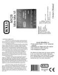
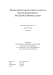
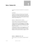
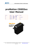
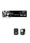
BALL BALANCING eingereichte PROJEKTARBEIT von Bsc. LI, Chao / Bsc. LIU, Yiliang Lehrstuhl für STEUERUNGS- UND REGELUNGSTECHNIK Technische Universität München Univ.-Prof. Dr.-Ing../Univ. Tokio Martin Buss Univ.-Prof. Dr.-Ing. Sandra Hirche Betreuer: Beginn: Zwischenbericht: Abgabe: Dipl. -Inf. Nicolai Waniek 18.04.2013 27.05.2013 18.06.2013 1 Abstract Ball Balancing is a challenging task concerning high requirement of real time property. The Ball Balancing experiment could be seen as a benchmark experiment for the robot balancing which view the robot only as the center point of it. The experiment takes one eDVS to get the ball’s position and velocity and uses a PID controller / fuzzy control from a computer / LPC Microcontroller to control the two actuators in order to keep the ball stand still on the center of the plate. 2 CONTENTS Contents 1 Introduction ----------------------------------------------------------------------------------- 5 1.1 Scheme of Mechanical Structure ------------------------------------------------------- 5 1.2 eDVS --------------------------------------------------------------------------------------- 6 1.3 Dynamixel Servo Motor ---- MX28T ------------------------------------------------- 6 1.4 Microcontroller --------------------------------------------------------------------------- 7 1.4.1 LPC1769 ----------------------------------------------------------------------------- 7 1.4.2 LPCxpresso IDE -------------------------------------------------------------------- 8 2 Anaysing Components and Methods ---------------------------------------------------- 9 2.1 eDVS Data Processing ------------------------------------------------------------------ 9 2.1.1 Background -------------------------------------------------------------------------- 9 2.1.2 Data Format ------------------------------------------------------------------------- 9 2.1.3 Tracking Algorithm --------------------------------------------------------------- 10 2.1.4 Noise--------------------------------------------------------------------------------- 10 2.2 Controlling MX28----------------------------------------------------------------------- 11 2.2.1 Driving of Motor directly by PC ------------------------------------------------ 11 2.2.2 Connection of Motor with LPC1769-------------------------------------------- 11 2.3 PID Control Algorithm ----------------------------------------------------------------- 16 2.3.1 Background of PID Controller --------------------------------------------------- 16 2.3.2 Implementation in Project (PID) ------------------------------------------------ 17 3 Results ----------------------------------------------------------------------------------------- 18 3.1 Connecting the System ----------------------------------------------------------------- 18 3.2 Results of the Project ------------------------------------------------------------------- 18 3.2.1 Component Level ------------------------------------------------------------------ 18 3.2.2 System Level ----------------------------------------------------------------------- 19 4 Summary and Outlook -------------------------------------------------------------------- 19 4.1 4.2 Summary --------------------------------------------------------------------------------- 19 Outlook ----------------------------------------------------------------------------------- 20 Bibliography --------------------------------------------------------------------------------------- 20 CONTENTS 3 5 1 Introduction In this project, the position and the velocity of the ball is tracked by one eDVS (Eventbased Dynamic Vision Sensor), with 2 servo motors driving a plate built in a specific mechanical structure which could be tilted in two dimensions. A microcontroller using PID control algorithm is aimed at controlling 2 motors on the basis of received sensor data to make them turn in order to keep the little ball stay within a small area of the plate and balanced at the plate. 1.1 Scheme of Mechanical Structure Figure 1: Mechanical structure Figure 1 is the mechanical structure used in this project. It is built using two plates with two servos in between and a vertical structure with the eDVS sensor mounted on the top. The two servos with each possesses one degree of freedom make sure the round plate could tilt in two dimensions 6 ERROR! USE THE HOME TAB TO APPLY ÜBERSCHRIFT 1 TO THE TEXT THAT YOU WANT TO APPEAR HERE. 1.2 eDVS eDVS (Event-based Dynamical Vision Sensor) is used to detect the movement of the ball in this project. eDVS could detect the change of the light intensity on the retina and feedback to the microprocessor as event as binary data. Figure 2: eDVS128[1] Figure 2 describes the eDVS128 which is also the one used in this project. It contains three major parts. The Lens which captures the change of light intensity, then the DVS sensor chip could turn the light signal to electrcial signal which could be processed by microcontroller. Then microcontroller would process the data and add time stamp. Above the microcontroller there is a FTDI chip which is a converter between Uart signal and the USB signal. 1.3 Dynamixel Servo Motor ---- MX28T Figure 3: MX28T 7 Dynamixel actuators have been widely used by our Neuron Computation Lab in the TU Munich. The actuator has an onboard microprocessor to facilitate bus communication, positional feedback, temperature and load monitoring. The torque, peed, and response are adjustable. In addition, position, load and voltage feedbacks are also available. Usually there are TTL and RS-485 serial communication that allows for daisy-chainable bus connections at up to 1-3mbps in the servo motor. In our case, we operate MX28T which complies with the network interface TTL (MX28R is RS485). What is also worth mentioning is that MX28T complies with PID. Additionally, the operating angle ranges from 0o to 360o. But one thing that should be mentioned is that in our entity the angle is quite limited(less than 40o). As a whole, MX28 is a high performance networked actuators for robots fully integrated with feedback function and programmability. Figure 4: USB2Dynamixel[2] What figure 4 is showing is USB2Dynamixel which is used to be connected between the actuator and the computer directly. Thus a PC can directly communicate with the actuator. 1.4 Microcontroller 1.4.1 LPC1769 The LPC1769 is a Cortex-M3 microcontroller developed by NXP Semiconductors for embedded applications featuring a high level of integration and low power consumption at frequencies of 120 MHz. Some important features include 512 kB of flash memory, 64 kB of data memory, 4 UARTs, 2 CAN channels, motor control PWM, ultra-low power Real-Time Clock with separate battery supply, and up to 70 general purpose I/O pins. The LPC1769 is pin-compatible to the 100-pin LPC2368 ARM7 MCU. 8 ERROR! USE THE HOME TAB TO APPLY ÜBERSCHRIFT 1 TO THE TEXT THAT YOU WANT TO APPEAR HERE. Figure 5: LPC1769 It can be applied in many areas such as e-metering, lighting, industrial networking, alarm systems, white goods, and motor control and so on. In our project, we use LPC1769 to operate the MX28. Figure 6: Debugger and Target[3] As figure 6 already shows, the whole LPCXpresso development board consists of two parts: LPC-Link debug interface and an NXP LPC ARM-based microcontroller target. The LPCXpresso target board includes an integrated JTAG debugger (LPCLink), so there’s no need for a separate JTAG debug probe. The target portion of the board can connect to expansion boards to provide a greater variety of interfaces, and I/O devices. The on-board LPC-Link debugger provides a high-speed USB to JTAG/SWD interface to the IDE and it can be connected to other debug targets such as a customer prototype. In our project, we use the LPCXpresso IDE to better perform the debugger as well as the target. 1.4.2 LPCxpresso IDE LPCXpresso is a development platform available from NXP. The software consists of an enhanced, elipse-based IDE, a GNU C compiler, linker, libraries, and an enhanced GDB debugger. The LPCXpresso IDE is based on the Eclipse development platform and 9 includes several LPC-specific enhancements. It is an industry-standard GNU tool-chain with an optimized C library. With these tools we can develop software solutions quickly and cost-effectively. LPCXpresso is based on Eclipse with many LPC specific enhancements. It also features the latest version of the industry standard GNU tool chain with a proprietary optimized C library providing professional quality tools. The LPCXpresso IDE can build an executable of any size with full code optimization. LPCXpresso supports the full embedded product design cycle by moving beyond chip evaluation boards and supporting development on external target boards. 2 Anaysing Components and Methods 2.1 eDVS Data Processing 2.1.1 Background eDVS sensor could detect the movement of the ball by sense the change of light intensity. The change of light intensity is converted to electrical signal and after the processing of the microcontroller; the data would be synchronized and sent to the computer with a time stamp. Depends on whether the light intensity is getting smaller or bigger it could be divided into two categories on event which the light intensity goes high from low and the off even in which the light intensity goes low from high. 2.1.2 Data Format There are several typical formats of data from eDVS sensors. In principle the eDVS sensor divides the detected space as a 128 by 128 matrix. It sends two bytes of information, one byte represent the x coordinate and the other byte represent the y coordinate, there is also one bit represent the polarity of the events (whether on event or off event) which is included in the x coordinate. 2.1.2.1 E+ This is the default data form. The eDVS continuously send two bytes of data for each on or off events. 0yyyyyyy pxxxxxxx, the first byte contains information about y coordinate of the matrix, the p in this case is a bit which determine the polarity of the event and the other x represents the x coordinate 10 ERROR! USE THE HOME TAB TO APPLY ÜBERSCHRIFT 1 TO THE TEXT THAT YOU WANT TO APPEAR HERE. 2.2.2 !E1 This data format has all the properties described above, besides that it contains byte that describe the time stamp of the event. Time stamp is the time point which the event occurs. 2.1.3 Tracking Algorithm The eDVS is used to track the ball. In this project the shape of the ball is totally ignored, only the mass point of the ball is taken into consideration. The algorithm calculated the mean value of all the on events and off events, the average value of coordinate of both on events and off events is considered to be the center of mass of the ball. Figure 8: Ball Tracking 2.1.4 Noise Noise is one of the biggest problems concerning the ball tracking. the reflection from the ball or the reflection from the plate or the thermo noise of the sensor itself contributes to the most of the noise source. A Butterworth Filter could be used as a physical filter to eliminate noise. However in this project a so called position filter is used. In which the continuous movement is assumed for the moving of the ball, it distribute different weight to different position difference. The new position which is further away from the old position is considered less likely to be true as a matter of fact, with a less weighting factor. The new position which is nearer to the old position is assumed be more likely which is given a higher weight. 11 2.2 Controlling MX28 2.2.1 Driving of Motor directly by PC 2.2.1.1 Basic Information The servo is the Dynamixel MX-28 which is provided by Korean company Robotis, which has 360° turning ability and a resolution of 0.088°. It uses a half-duplex communication protocol to communicate other devices. More specifically in this project the TTL protocol is used. The servo also needs an adapter (USB2Dynamixel) which could convert the data form Uart form to the USB form, setting the bridge between the computer and the servo. Other than that the power supply of the servo is provided by an extra cable directly connected to the socket. 2.2.1.2 Communication The communication is realized by a Matlab based interface. Matlab 2013a and Visual Studio 2010 Ultimate are used to call the function from the dll file named dynamixel.dll which is provided by Robotis. A short source code is written using Matlab with simple command to set the ID of the two servos, and simple command aiming at controlling the turning degree and the angular velocity is written 2.2.1.3 Motor Driving Two servos are series connected with each other with ID of 1 and 2 separately. As a separation the servo with ID = 1 is labeled with a white dot and the servo with ID = 2 is labeled with a red dot. All the command that could be sent to the servo are stored in the dll file and there is an control table provided by the Robotis with API references which give guidance for user to control the Servo. Because of the limitation from the mechanical structure only limited degree of angle turning is possible. In this project both servos are only allowed to turn a maximal from -45° to 45°. 2.2.2 Connection of Motor with LPC1769 2.2.2.1 Connection to UART To control the Dynamixel actuators, the main controller needs to convert its UART signals to the half-duplex type. In our project we adopt such circuit diagram that is shown below. 12 ERROR! USE THE HOME TAB TO APPLY ÜBERSCHRIFT 1 TO THE TEXT THAT YOU WANT TO APPEAR HERE. Figure 9: TTL solution The connector pin assignments are as the following. The two connectors on the Dynamixel are connected pin to pin, thus the Dynamixel can be operated with only one connector attached. MX28 works with half-duplex. That means RX und TX are in one cable (pin: DATA). In order to connect it to our microcontroller LPC1769, we must first do something before. There are three pins on MX28. From above downwards are successively GND, VDD and DATA. As mentioned and depicted above: RX of the microcontroller should be connected directly with motor-DATA. TX should first connect to a resister of 10Kohm and then to motor-DATA. TX and RX should be soldered together. The motor needs a power supply of at least 11 Volt. The microcontroller can be linked to computer with a USB 2.0 A/Mini-B cable in order to get power supply. That means we don’t need VDD-pin. 2.2.2.2 UART and Pin Assignment There exists 4 UART in the LPC1769. Because UART0 and UART1 in some cases may have its specific functions, in this project, we have chosen UART3 as our communication interface. 13 Figure 10: TTL solution Here is the whole schematic for the LPCXpresso. According to what have been analyzed above, on the left side the pin “GND”, pin “P0.0” and pin “p0.1” are chosen, which is respectively the ground cable, TX3 and RX3. Then, the actuator and microcontroller can be connected with each other by soldering following the proposed rule. Figure 11: Connection between LPC1769 and MX28(both must have extern power supply) 15 2.2.2.3 Development on LPCxpresso IDE The LPCXpresso IDE includes several sample code bundles for various development boards. In “UART.c”, three most important functions are UART3_IRQHandler ------ UART3 interrupt handler. UARTInit ------ Initialize UART port, setup pin select, clock, parity, stop bits, FIFO, etc. UARTSend Send a block of data to the UART 3 port based on the data length. For the configuration of UART3, we must follow the LPC user manual. The following must be configured. We check each table to see the right bits and right address for certain functions. Figure 13: Basic Configuration Set MX28 active (set 1) Define motor variables ( Position, speed) Initialize parameters of LPC_UART3 and MX28 Update new data every 1,5 or 20s Sent requests, get requests Loop: check for new data on uart3 16 BIBLIOGRAPHY Figure 14: Scheme of a simple operation on MX28 through LPC1769 In order to check if UART3 works well, MX28 should be connected to LPC1769 not only physically but also in IDE. In the same project, we establish “MX28.h” and “MX28.c” to control the motor direct by the microcontroller. Here I list some very important functions that must be defined and adopted to control the motor: Among these, to receive the data from motor is very slow. After giving a request acquiring data, we must wait for a long time. The configuration of MX28 must be corresponding to which of UART3. That means, the communication interface must be seamless abutted. For example, LPC_PINCON->PINSEL0 |= 0x0000000A; in “MX28.c” is to enable TxD3, RxD3 output pins. Similarly, LCR, DLM, DLL, FDR, IER, FCR, etc. must also correspond to UART3. Figure 14 shows the basic scheme of controlling MX28 through LPC1769. According to that a main function has been composed to call the related functions. 2.3 PID Control Algorithm 2.3.1 Background of PID Controller PID controller is one of the widely used and classic controllers in industry. One of the major merits of this controller is its application for unknown system. At the lack of precise understanding of the system itself, certain control could be realized by this control method. Figure 15: PID Controller[4] Figure 2.2 shows the block diagram of a typical PID controller. The PID controller is normally used in a closed loop. It fetch the error between the set value and the real value of the output as the input for the controller and return the processed the error to the plant 17 process which is the system itself. The system itself could normally be described as a dynamical system which composed of a set of differential equations. The PID controller in this project is implemented using Matlab by programming the existed PID model. The system is described as differential equations which are derived from the physical law 2.3.2 Implementation in Project (PID) The detail description of the system remains unknown, which means the relation between turning angle and the velocity of the ball remains unknown. Figure 16: System Scheme The relation between 𝜃 and 𝑥 is unknown in this system. As the mass and also diameter of the ball is unknown. In this project the relation between them are determined experimentally. As different velocity 𝑣 are tested with different angles the following relation has been determined. 𝜃 0 5 10 20 30 40 𝑣 0 2.7 5.5 8.5 9 10 The unit of the angle is degree and the unit of velocity is pixel per meter. There is no need to match every unit to the international standard unit, as the parameter of PID controller could also function as a correct factor. The displacement 𝑥 is the integral of 𝑣 with time 𝑡. As the relation between 𝑣 and 𝜃 is clear, it is relative easy to derive also the relation between 𝑡 and 𝑥 18 BIBLIOGRAPHY 3 Results 3.1 Connecting the System The system is built by connecting two servos and the eDVS to the computer and is placed two sensors and the eDVS on the mechanical structure. The eDVS detects the ball and transmits the data to the computer; the events sent from eDVS will be processed by the computer to get the position and velocity of the ball. The position and velocity of the ball would be processed by the PID controller programmed within computer to send the angle the servo should turn and also the turning velocity. Mainly through the function of the PID controller, the ball should be able to stay within certain area from the middle point. Figure 17: A picture of the system 3.2 Results of the Project 3.2.1 Component Level The simulation and processing of every main component has worked successfully. First, the eDVS could fetch data from events changing and the computer is able to process these events to get the real time position and the velocity of the metal ball. 19 Secondly, UART3 communication has been successfully established. Sending data per UART3 with PC can be realized. Moreover, the motor could be driven successfully to turn to arbitrary angle with arbitrary angular velocity within the physical standard of these servos directly through PC. However, to control the actuator with LPC is still expected to be realized though the UART protocol and configuration of motor have been finished successfully. Possible reasons could be the loop algorithm is not fit enough for the actuator. At last, the PID controller is successfully implemented in the computer with a descent impulse response. 3.2.2 System Level The integration of the PID controller to the system could not function successfully. This is the missing Link of this project, further work required to be done on this topic. 4 Summary and Outlook 4.1 Summary The whole structure of the project is now clarified as below: Motor eDVS PID controller LPC Total system Figure 18: Overview of Whole System As has mentioned already, most of the module functions have been realized successfully . The component driving and processing has been quite successful, the system level integration and tuning require. 20 BIBLIOGRAPHY 4.2 Outlook As mentioned before the system level integration and tuning requires urgent improvement. This project could be seen as a know-how project to understand the balancing mechanism in the robot industry, in which the robot could be simply seen as its center point. The ball balancing should require to extend to balancing of rigid body of certain shape, a step further, a multi-body balancing could achieved as a direct model of Robot balancing system. Bibliography [1] https://wiki.lsr.ei.tum.de/nst/programming/edvsgettingstarted [2] http://support.robotis.com/en/product/auxdevice/interface/usb2dxl_manual.htm [3] http://www.nxp.com/techzones/microcontrollers-techzone/tools ecosystem/lpcxpresso.html [4] http://en.wikipedia.org/wiki/PID_controller 21