1
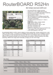
ST5801GB Series Outdoor AP/Bridge User Manual
Kareem
Contents
Chapter 1: Product Overview.............................. 3
Introduction.......................................................... 3
Installation............................................................ 3
Package Contents..................................................4
Chapter 2: System Configuration........................ 5
System Setup.........................................................5
System Setup > Basic Setup................................. 5
System Setup > Network Setup........................... 6
Wireless.................................................................7
Wireless > Radio Setup........................................ 7
Wireless > WLAN Setup....................................... 7
Wireless > Wireless Security............................... 8
Wireless > WMM Setup........................................ 9
Wireless > Bandwidth Control.......................... 10
Administration................................................... 10
Administration > Management......................... 10
Administration > Login Password.................... 11
Administration > SNMP Setup...........................11
Utility...................................................................12
Utility > Ping....................................................... 12
Utility > RSSI Calculator.....................................12
Utility > Fresnel Zone.........................................12
Utility > Antenna Alignment Tool..................... 12
Utility > Site Survey............................................13
Status................................................................... 13
Status > System Information............................. 13
Status > System Status....................................... 13
Status > Connecting Nodes Information...........14
Status > Connecting AP Information.................14
Appendix 1: Specifications.................................15
Hardware Specification..................................... 15
Software Specification....................................... 18
2
Chapter 1: Product Overview
Introduction
integrated with central RADIUS server and data
encryption technique, the ST5801GB SERIES
OUTDOOR AP/BRIDGE series provide a secure
wireless connectivity for each client device.
The ST5801GB SERIES OUTDOOR AP/BRIDGE series
are enterprise and carrier-grade 802.11N Outdoor
Wireless Access Point which offers customer a robust
and high performing solution for PTP/PTMP/Hotzone
applications in both license-free 2.4GHz and 5GHz
bands.
The ST5801GB03R is the most ideal candidate for
Service Providers looking to deliver carrier-grade
wireless services to multiple market segments such
as campuses, hospitality, healthcare, warehousing
and wider metropolitan area deployments.
Designed to meet customer needs in a broad range
of industries, the ST5801GB SERIES OUTDOOR
AP/BRIDGE offer the following benefits :
ST5801GB SERIES OUTDOOR AP/BRIDGE
Category
Model
Radio Spec.
Radio
Amount
ST5801GB01R
Dual-Band 2x2 MIMO
Normal Power
1
ST5801GB02R
Dual-Band 2x2 MIMO
Normal Power
2
ST5801GB03R
Dual-Band 2x2 MIMO
Normal Power
3
ST5801GB01R
H
Dual-Band 2x2 MIMO
High Power
1
ST5801GB02R
H
Dual-Band 2x2 MIMO
High Power
2
Flexible wireless backbone deployment options
Multiple radio interfaces were integrated by
FonSee’s core data switching technology inside the
ST5801GB SERIES OUTDOOR AP/BRIDGE series. Each
radio interface can be configured independently to
meet different wireless connectivity purposes. With
the fast data switching between multiple radio
ST5801GB03R
H
Dual-Band 2x2 MIMO
High Power
3
interfaces, the backbone throughput will remain in a
high level even after several relays between APs.
interfaces. Each 2X2 MIMO radio interface will has 2
N-type connectors come out on the waterproof
housing. We strongly recommend that check
antenna attachment to match your configuration
before the installation.
High-performance wireless backbone
With the next generation 802.11N MIMO technology,
the ST5801GB SERIES OUTDOOR AP/BRIDGE offer
data link rate up to 300Mbps in each single radio
interface. Short Guard Interval and Frames
Aggregation methodology configurations improve
the efficient of backbone usage.
Installation
The ST5801GB SERIES OUTDOOR AP/BRIDGE series
product has up to 3 dual-band 2X2 MIMO radio
Secure and efficient client connectivity
The nimble QoS (Quality of Service) configuration
provides flexible management of user’s access
bandwidth of wireless connectivity. Perfect
3
Package Contents
A PoE is the power supply of the ST5801GB SERIES
OUTDOOR AP/BRIDGE series. Please connect the
ETH1+Power port to the included PoE injector by
Ethernet cable.
● ST5801GB SERIES OUTDOOR AP/BRIDGE
802.11A/G/N Outdoor Wireless Bridge
● PoE Power Injector
● Power Adapter
● Mounting Kit & Screw
● CD: User Manual
Connect another data port on the PoE injector to
your LAN switch or PC, if necessary.
4
Chapter 2: System Configuration
Access the Browser-Based Utility
System Setup
To access the system web user’s interface, launch the
web browser on your computer, and enter the
device IP address in the Address field of the web
browser. (The factory default IP address is
192.168.1.1.) Then press Enter.
A System Setup includes device related elements,
such as system time and IP setting.
A login screen will appear. Go to the login page by
Click the “Home > Login” in sub-menu. Login ID and
password is required before access the system web
user’s interface. The default administrator’s ID is
admin and password is admin. For normal user’s
login ID is user and password is user. Configuration
will be not available for user account.
System Setup > Basic Setup
Language The ST5801GB SERIES OUTDOOR
AP/BRIDGE series WEB GUI is designed to support
English language in display. Users can choose the
proper language in language list.
Device Name User would like to give a name for
identifying a particular outdoor access point in here.
The configuration page was vertically divided into
right and left part. Items in the left part show the
concurrent configuration corresponds to the items in
right part.
System Date User would like to set the date
manually in this item.
System Time User would like to set the time
manually in this item.
Please do remember to click the Apply button on the
very bottom of every page to make your
configuration changes effected; otherwise the
changes you just made will be ignored once you
Time Synchronization Time synchronization setting
will decide the duration to next time synchronization.
When any NTP server is available in network, user
can enable the NTP and system will automatically
leave the current page. You can also click the Cancel
button to regret the changes.
synchronize system time with NTP server.
GMT Time zone Set a Greenwich Mean Time setup
5
for time synchronization.
Time Server User can insert an available IP address
of NTP server in Internet for time synchronization.
System Setup > Network Setup
IP Setup
STP The Spanning Tree Protocol (STP) is a network
protocol that ensures a loop-free topology for any
bridged Ethernet local area network. The basic
function of STP is to prevent bridge loops and
ensuing broadcast radiation. Spanning tree also
allows a network design to include spare (redundant)
links to provide automatic backup paths if an active
link fails, without the danger of bridge loops, or the
need for manual enabling/disabling of these backup
links.
Ethernet Link Speed
IP Assignment System allows you to assign the
device IP address dynamically from existing DHCP
server or set a static IP address manually.
IP Address Once Static IP was selected, the IP
Address field will allow you to set the bridge device
IP address manually. This IP address of the bridge is
used as the base for all of your local network
settings.
Link The link speed of Ethernet port can be changed
manually into 10/100 Half/Full duplex.
DHCP Server Setting
The ST5801GB SERIES OUTDOOR AP/BRIDGE series
can be configured as a DHCP server for a LAN
network. Once the DHCP Server is chose as on, the
DHCP server setting elements will spread out on the
page.
Subnet Mask This is the subnet mask address for
your bridge device. Set the IP subnet mask manually.
Default Gateway Set the default gateway IP address
manually.
DNS 1 & 2 The Domain Name System (DNS) is how
the Internet translates domain or website names
into Internet addresses or URLs. Your ISP will provide
you with at least one DNS Server IP Address. If you
wish to use another, enter that IP Address in DNS 2
field.
DHCP Server Allows you to enable or disable the
DHCP server function in system.
IP Start / End The IP Start and End Address specify
the range of addresses assigned by your device when
it functions as a DHCP server.
Spanning Tree Protocol
Primary & Secondary DNS Set the primary and
6
secondary DNS server IP address which DHCP server
is going to assign for DHCP client devices.
Default Gateway Default gateways IP address assign
for DHCP client devices.
Management VLAN
Management VLAN Management VLAN is a secure
VLAN which divides Internet users from device IP
access. Administrators can management network
devices under the Management LAN network
without betrayal of secrets.
Wireless
Wireless > Radio Setup
Channel Available channel will relate to what
wireless band is chosen.
Transmission Power Control the transmit power of a
radio by selection of Transmission Power.
Antenna Number ST5801GB SERIES OUTDOOR
AP/BRIDGE series complete 802.11n 1x1 1-steram
and 2x2 2-stream for antenna attached. The
maximum data link rate at 1-steram and 2-stream
will be 130Mbps and 300Mbps.
Short Guard Interval The guard interval is the space
Wireless Band Choose a radio frequency for signal
transmission. The frequency and channel bandwidth
match to selection is showed as following table:
between symbols (characters) being transmitted.
Adding time between symbol transmissions allows
these echoes and reflections to settle in before the
next symbol is transmitted.
In normal 802.11
operations, the guard interval is 800 ns. A short
guard interval will short the time between symbol
transmissions into 400 ns to enhance the efficiency
of data transmission.
Aggregation Frame aggregation is a feature of the
802.11n wireless LAN standards that increases
throughput by sending two or more data frames in a
single transmission.
Distance To assign a distance between nodes in a
7
point to point transmission will improve the success
rate of data transmit.
Wireless > WLAN Setup
Each physical radio interface supports up to 16
virtual WLAN AP setting. User can add or delete a
virtual AP by click the “+” or “-” button on top of the
very right side of setting block.
SSID A service set identifier (SSID) is a name that
identifies a particular 802.11 wireless LAN. A client
device receives beacon messages from all access
points within range advertising their SSIDs. The client
device can then either manually or automatically
select the network with which to associate.
Broadcast Network administrator can choose
broadcast beacon messages of a virtual AP by
checking the broadcast block.
RTS “Request to send” is the optional mechanism
used by the 802.11 wireless networking protocol to
reduce frame collisions introduced by the hidden
node problem. Set the packet size to trigger RTS/CTS
enable. This is normally set in AC side only because
the hidden station problem does not exit from the
perspective of the AP. RTS Threshold can be set
between 1 and 2312 bytes.
Fragmentation Set the packet size to activate
fragmentation. Fragmentation threshold can be set
between 1 and 2312 bytes.
Note: Fragmentation setting will be automatically
disabled, once the frame aggregation is enabled.
Limited Data Rate Limit the wireless data link rate to
enhance the stability of data transmission.
VLAN ID In order to create a wireless VLAN
environment, each virtual AP can conform to an
802.1q VLAN tag ID.
VLAN Priority Each VLAN ID can be gave a priority
number (from 0 to 7) for data process priority.
Client Numbers Limit the maximum number of
associate client devices.
Client Isolation Client isolation will protect the
privacy of each connecting client from searching in a
wireless LAN.
Enable Network administrator can also decide
functioning of virtual AP or let it idle.
WLAN Mode Radios support “Access Point”,
“Wireless Station”, “Access Point (WDS Support)”
Bandwidth Profile Choose a bandwidth control
profile for virtual AP interface. (About the detail of
bandwidth profile, please refer to the bandwidth
control setup in coming pages.)
Wireless > Wireless Security
and “Wireless Station (WDS Support)” mode to meet
various network scenarios.
8
of WEP key as shown in the table are entered. Note
that in HEX format, HEX number cannot start with
“0”.
SSID User can choose a specific virtual AP to assign a
security type of wireless link.
MAC Filter MAC filter provides allow or deny MAC
table for administrator to access control of AP by
insert a MAC address of client device. When running
allow mode, only the MAC address which showing
on the table will be accept for wireless connectivity.
When running deny mode, MAC address which
showing on the table will be blocked from wireless
connectivity. The table can be configured 32 MAC
address at most of each virtual AP interface.
Number of digit/character
ASCII
HEX
64-bit
5
10
128-bit
13
26
152-bit
16
32
WPA+WPA2-PSK ST5801GB SERIES OUTDOOR
AP/BRIDGE
series
support
WPA+WPA2-PSK
(WPA-Personal)
in
security.
WPA+WPA2-PSK
(Pre-shared key) mode is designed for home and
small office networks and doesn't require an
authentication server. Each wireless network device
authenticates with the access point using the same
256-bit key.
TKIP Temporal Key Integrity Protocol: A 128-bit
per-packet key is used, meaning that it dynamically
generates a new key for each packet. Used by WPA.
CCMP An AES-based encryption mechanism that is
stronger than TKIP. Sometimes referred to as AES
instead of CCMP. Used by WPA2.
Both TKIP and CCMP encryption are available for
WPA+WPA2-PSK. Pre-shared key of 8 to 63
characters are required. Group Rekey Interval can be
set up to 65536 seconds.
Wireless > WMM Setup
Security Comprehensive security settings are
available on system in this menu. These include WEP
Keys and WPA+WPA2-PSK. Details of each type of
security are in appendix. The security settings are
independent between each virtual AP interface.
WEP System supports 64-bit, 128-bit and 152-bit
WEP key in both ASCII and HEX format. Do make sure
the correctly number of digits/characters and format
Wi-Fi Multimedia (WMM) is a Wi-Fi Alliance
interoperability certification, based on the IEEE
9
802.11e standard. It provides basic Quality of service
(QoS) features to IEEE 802.11 networks. WMM
prioritizes traffic according to four Access Categories
(AC) - voice, video, best effort, and background. It is
suitable for simple applications that require QoS,
such as Voice over IP (VoIP) on Wi-Fi phones
(VoWLAN).
10
Administration
Wireless > Bandwidth Control
ST5801GB SERIES OUTDOOR AP/BRIDGE series
provide system management in menu partition:
Administration, Which includes configuration file
management, password maintaining and SNMP
setup.
Administration > Management
Profile ID There are 20 bandwidth control profiles
can be configured for administration.
Mode Downstream and upstream data rates for
subscriber or the client devices connecting to AP can
be defined here. There are two bandwidth limit
types in system. Both mode (UL+DL Limit Rate)
consolidates download and upload rate of each
single client connection. UL/DL mode (UL/DL Limit
Rate) specifies download and upload rate of client
connections. Once the bandwidth limit is enabled,
the limitation applies to all clients that connect to
the AP.
Firmware Upgrade Administrator can upload a new
firmware file to device to keep system running by the
latest bug fixed version of firmware.
Configuration Management Administrator would
like to save the configuration of device to local PC by
click “Backup Configuration”. Once hardware
damage happened, administrator can restore a
saved configuration file to a new hardware without
any reconfiguration. “Reset Default” allows
administrator to reload the system to factory default.
System Restart Click the “System Reboot” button
will help to warm start the system.
11
Administration > Login Password
SNMP V3
System allows administrator to change the “admin”
and “user” login password in menu partition: “Login
Password”.
Administration > SNMP Setup
RW User Name Read and write authority login ID.
RW User Password Read and write authority login
password.
RO User Name Read only authority login ID.
ST5801GB SERIES OUTDOOR AP/BRIDGE series
support both SNMP V2 and V3. The configurable
items show below:
System Location A description notes the device
location.
System Contact A description notes the device
maintaining information.
RO User Password Read only authority login
password.
AUTH method Choose the user authentication
method.
ENC method Choose the SNMP data encryption
method.
SNMP V2C
System Name A description notes the given name of
device.
RW Community Read
community stream.
and
write
authority
RO Community Read only authority community
stream.
12
Utility
Utility > Fresnel Zone
ST5801GB SERIES OUTDOOR AP/BRIDGE series
provide
various
software utilities helping
administrator to do the network status survey.
Utility > Ping
The First Fresnel Zone Calculator is a tool that helps
you to estimate the possible obstruction from
existing object between two devices before the
wireless installation. An antenna angle calculation
can also help you to aligning the vertical angle of the
directional antenna.
Graphical display helps administrator to get the
responding time changes of target IP address. Insert
the remote host IP address, packet size and number
in field than press Ping, system will show the result
on page. The result presenting can be adjusted by
different choosing of graphic scale.
Utility > RSSI Calculator
Utility > Antenna Alignment Tool
In order to lift efficiency of antenna aligning,
AMP-100R(H) series provide a software alignment
tool helping the installers to align and check the
antenna directions.
Antenna Alignment Tool will require triggering the
function both access point and wireless station (AP
Client) side. It means that both access point and
wireless station (AP Client) side should be the
ST5801GB SERIES OUTDOOR AP/BRIDGE series
product, otherwise, the function doesn’t get
properly use.
Simple RSSI Calculator helps to estimate a possible
RSSI and path loss by known device Tx power
(transmission power), cable loss, antenna gain and
frequency both transmitting and receiving side.
Graphic displaying shows changes of path loss and
RSSI.
Choose the SSID which you are going to do the
13
antenna aligning and click the Star button both
access point and wireless station (AP Client) side to
start the antenna alignment. You will able to see the
RSSI changes in figure. Try to adjust the directional
antenna’s horizontal and vertical angle to get the
best RSSI level.
Link Test
A Link Test is additional tool base on Antenna
Alignment Tool active status. When you start the
Antenna Alignment Tool, you may set a target
throughput to active the Link Test to estimate the
packet error rate.
Choose a target throughput and test duration than
click Start Test button. System will generate a test
data transmission to calculate the packet error rate.
Status
Status > System Information
System Information summarizes all the configuration
and hardware information of the device.
Status > System Status
An Rx rate shows the best data rate you can reach
under the current RSSI level.
Link Test Tool can also help you to do the fine tuning
of your antenna direction.
Utility > Site Survey
Real-time link statuses of all interfaces are shown in
the menu.
In wireless site survey, system provides a signal scan
function to detect any available wireless signal
around the AP. It will help AP installer to clarify the
environment. Choose a radio interface which you are
going to do the survey on device and click Scan
button. After few seconds, system will show the APs
around the device.
System Up Time Display how long ST5801GB SERIES
OUTDOOR AP/BRIDGE has been operating since last
boot-up.
Interface Status Indicate the interface is ENABLE or
DISABLE.
Link Rate Data Link Rate here indicates the
maximum transmission rate available, and can be
14
used as an indication of link quality.
Link Quality A Calculation of RSSI, signal and noise
level to indicate the quality of the communication
link in percentage.
Channel The channel used by the wireless interface.
Graphic display is also available for observing the
changes.
Signal Level A -70 ~ -50dBm signal level is
recommended for a good connection. Too low a
signal, the wireless link between AP and AC cannot
be established. Too high a signal level, the power
amplifier at the receiver might be forced to operate
in saturation region and distorts the signal
waveform.
Status > Connecting AP Information
In order to help user’s reading of the changes,
system also provide a graphic interface to trace the
items’ changes. Click the Graphic Display button on
the top left of the page, graphic mode will show on
your browser.
In the “Connecting AP Information” page, RSSI, Rx
rate, Tx rate and etc. are provided for verification of
wireless link status.
Graphic display is also available for observing the
changes.
Status > Connecting Nodes Information
All the connecting clients’ MAC address will be
display in Connecting Nodes Information, including
signal and data rate. The result shows information
only when WLAN was configured as Access Point
mode.
15
Appendix 1: Specifications
Hardware Specification
System Overall
Peripheral
Main Processor
Atheros AR7161(680Mhz)
Wireless Chipset
Atheros AR9220 based miniPCI
module, Up to three modules
Switch Controller
Atheros AR8035 / Atheros
AR8021
Flash Memory
16MBytes
SDRAM
64MBytes(Up to 128MBytes)
Console
UART x 1(PCBA onboard)
RTC
Onboard RTC
PoE
48V 1A PoE
Ethernet
Gigabit Speed Support
Wireless
Up to three 2x2 MIMO radios,
mini-PCI version 1.0 type 3A
Frequency ranges :
a. USA : 2.400 ~ 2.483 GHz, 5.15 ~
5.35 GHz, 5.5 ~ 5.7 GHz, 5.725
~ 5.825 GHz
b. Europe: 2.400 ~ 2.483 GHz, 5.15
~ 5.35 GHz, 5.47 ~ 5.725 GHz
c. Japan: 2.400 ~ 2.497 GHz, 5.15 ~
5.35 GHz, 5.47 ~ 5.725 GHz
d. China: 2.400 ~ 2.483 GHz, 5.725
~5.85 GHz
RF ourput power of DNMA-92 :
a. IEEE802.11a
1. 21dBm@6M(all)
2. 17dBm@54M(5180MHz)
16dBm@54M(5825MHz)
b. IEEE802.11b
1. 20dBm@1M(2412MHz)
19dBm@1M(2484MHz)
2. 21dBm@11M(all)
c. IEEE802.11g
1. 23dBm@6M(all)
2. 19dBm@54M(all)
d. IEEE802.11a/n HT20
1. 21dBm@MCS0/8(5180MH
z)
19dBm@MCS0/8(5825M
Hz)
2. 16dBm@MCS7/15(5180M
Hz)
16
14dBm@MCS7/15(5825
MHz)
e. IEEE802.11a/n HT40
1. 19dBm@MCS0/8(5190MH
z)
18dBm@MCS0/8(5795M
Hz)
2. 13dBm@MCS7/15(all)
f. IEEE802.11g/n HT20
1. 21dBm@MCS0/8(all)
2. 17dBm@MCS7/15(all)
g. IEEE802.11g/n HT40
1. 21dBm@MCS0/8(2422MH
z)
20dBm@MCS0/8(2462M
Hz)
2. 16dBm@MCS7/15(all)
Receive Sensitivity of DNMA-92 :
a. IEEE802.11a
1. -82dBm@6M, 1Rx
-95/-91dBm@6M, 2Rx
2. -65dBm@54M, 1Rx
-79/-75dBm@54M, 2Rx
b. IEEE802.11b
1. -82dBm@1M, 1Rx
-95/-91dBm@1M, 2Rx
2. -76dBm@11M, 1Rx
-91/-87dBm@11M, 2Rx
c. IEEE802.11g
1. -82dBm@6M, 1Rx
-95/-91dBm@6M, 2Rx
2. -65dBm@54M, 1Rx
-80/-76dBm@54M, 2Rx
d. IEEE802.11a/n HT20
1. -82dBm@MCS0, 1Rx
-95/-91dBm@MCS0, 2Rx
2. -64dBm@MCS7, 1Rx
-77/-73dBm@MCS7, 2Rx
e. IEEE802.11a/n HT40
1. -79dBm@MCS0, 1Rx
-91/-87dBm@MCS0, 2Rx
2. -61dBm@MCS7, 1Rx
-74/-70dBm@MCS7, 2Rx
f. IEEE802.11g/n HT20
1. -82dBm@MCS0, 1Rx
-95/-91dBm@MCS0, 2Rx
2. -64dBm@MCS7, 1Rx
-77/-73dBm@MCS7, 2Rx
g. IEEE802.11g/n HT40
1. -79dBm@MCS0, 1Rx
-90/-86dBm@MCS0, 2Rx
2. -61dBm@MCS7, 1Rx
-74/-71dBm@MCS7, 2Rx
RF output power of DNMA-H92 :
a. IEEE802.11a
1. 24dBm@6M(all)
2. 21dBm@54M(all)
b. IEEE802.11b
1. 24dBm@1M(all)
2. 24dBm@11M(all)
c. IEEE802.11g
1. 25dBm@6M(all)
2. 22dBm@54M(all)
d. IEEE802.11a/n HT20
1. 24dBm@MCS0/8(all)
2. 18dBm@MCS7/15(5180M
Hz)
17dBm@MCS7/15(5825
MHz)
e. IEEE802.11a/n HT40
1. 22dBm@MCS0/8(all)
2. 17dBm@MCS7/15(5190M
Hz)
17
16dBm@MCS7/15(5795
MHz)
-95/-91dBm@MCS0, 2Rx
2.
f. IEEE802.11g/n HT20
-77/-73dBm@MCS7, 2Rx
1. 25dBm@MCS0/8(all)
g. IEEE802.11g/n HT40
2. 21dBm@MCS7/15(all)
1.
g. IEEE802.11g/n HT40
2.
2. 20dBm@MCS7/15(all)
Ethernet
10/100/1000 Base-TX MDI/MDIX
RJ-45 x 1
-82dBm@6M, 1Rx
-95/-91dBm@6M, 2Rx
2.
Compliant with :
-65dBm@54M, 1Rx
a. IEEE802.3 / 802.3u / 802.3at
-79/-75dBm@54M, 2Rx
b. Hardware based 10/100/1000,
full/half, flow control auto
negotiation
b. IEEE802.11b
1.
-82dBm@1M, 1Rx
-92/-88dBm@1M, 2Rx
2.
c. IEEE802.11g
-82dBm@6M, 1Rx
-95/-91dBm@6M, 2Rx
2.
-65dBm@54M, 1Rx
-80/-76dBm@54M, 2Rx
d. IEEE802.11a/n HT20
1.
Connector
2 x N-type(1 radio)
4 x N-type(2 radios)
6 x N-type(3 radios)
Power
Requirement
48V 1A PoE
Support Gigabit Ethernet Link
Watch Dog
Hardware Watch Dog
-76dBm@11M, 1Rx
-92/-88dBm@11M, 2Rx
1.
-61dBm@MCS7, 1Rx
-74/-70dBm@MCS7, 2Rx
a. IEEE802.11a
1.
-79dBm@MCS0, 1Rx
-92/-88dBm@MCS0, 2Rx
1. 24dBm@MCS0/8(all)
Receive Sensitivity of DNMA-H92 :
-64dBm@MCS7, 1Rx
-82dBm@MCS0, 1Rx
Physical
Dimensions
220 x 220 x 77 mm
Weight
2.0kg(3.7kg mount kit included)
Water and
Dust Proof
Outdoor IP67 rated
-95/-91dBm@MCS0, 2Rx
2.
-64dBm@MCS7, 1Rx
-77/-73dBm@MCS7, 2Rx
e. IEEE802.11a/n HT40
1.
Environmental
Temperature Range
-20 ~ 70°C
Humidity
0~95%
-79dBm@MCS0, 1Rx
-91/-87dBm@MCS0, 2Rx
2.
-61dBm@MCS7, 1Rx
-73/-69dBm@MCS7, 2Rx
f. IEEE802.11g/n HT20
1.
-82dBm@MCS0, 1Rx
18
Software Specification
System Operation
Performance
Layer 2 Switching Learning
Technology
TCP
Store-and-Forward
Bridge Mode
Spanning Tree Protocol - IEEE
802.1d STP / IEEE 802.1w RSTP
Static IP
DHCP server / client
IEEE 802.1q Tag VLAN
Wireless
UDP
To
Wire
IEEE 802.1p VLAN Priority Based
QoS
PPS
Network Interface
Up to 180Mbps for one radio
to Ethernet
Up to 320Mbps for multiple
radios to Ethernet
Up to 240Mbps for one radio
to Ethernet
Up to 350Mbps for multiple
radios to Ethernet
>= 20,000@short packet for
one radio to Ethernet
>= 28,000@short packet for
multiple radios to Ethernet
IEEE 802.11 a/b/g/n 2.4GHz / 5GHz
Dual Band Radio
Latency
< 5ms
2 hops
Up to 160Mbps
2 x 2 MIMO Technology
3 hops
Up to 150Mbps
>= 4hops
Up to 140Mbps
PPS
>= 20,000@short packet at
multiple hops
Latency
< 10ms
Single Radio / Dual Radios / Triple
Radios
Multiple
Hops
AP mode / Client mode
WDS Support enable / disable
IEEE 802.11h DFS
Wireless
WMM QoS
Security
Channel / Tx Power / Data Rate /
Hide SSID(turn off ESSID broadcasting)
Max Distance Adjustable
MAC Address ACL
Multi-SSIDs / VLAN tags mapping(Up
to 16 x ESSIDs for each radio)
WEP 64/128/152 bits
Wireless Site Survey
WPA / WPA2 PSK / EAP with TKIP / CCMP AES based
Encryption
Node Information
IEEE 802.1x EAP-MD5 / EAP-TLS / EAP-TTLS
Concurrent Connected Node
Limitation
Client User Isolation
48V 1A PoE
Support Gigabit Ethernet Speed
Wire
Ethernet Link Speed Configurable
10/100/1000 Base-TX MDI/MDIX
RJ-45
19
Management
Advanced Technology
HTTP(s) WEB GUI
Telnet
Up to 10 hops with more than
120Mbps throughput
Multiple Hopping
Configurable Max. Hop
Counts(default 20 hops)
SSH
Console(optional interface)
CLI commands
Advanced
Features
Wireless Bandwidth Limitation
SNMP v2c/v3, standard / private MIBs
Syslog
Management VLAN Tag
NTP Client
Firmware upgrade / downgrade
Dual Images
Dual Configuration files / Factory Default
Multiple Level Management
20