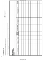
1
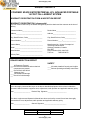
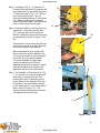
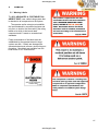
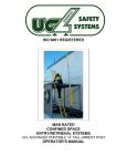
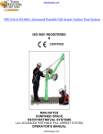
actoolsupply.com
DBI SALA 8516996 Advanced Portable Fall Arrest Post
actoolsupply.com
actoolsupply.com
actoolsupply.com
actoolsupply.com
LIMITED WARRANTY
This Limited Warranty is given exclusively to:
Name
Address
Telephone No.
by Unique Concepts Ltd. (“Unique Concepts”) in respect of the following product(s) manufactured by it
(the “Products”):
Subject to the conditions and restrictions contained in this Limited Warranty, Unique Concepts warrants to
the Customer that the Products are free from defects in materials and workmanship under normal use
and service for a period of twelve (12) months from the date the Products are purchased by the
Customer, in new and unused condition, from Unique Concepts or its agent (the “Warranty Period”).
Unique Concepts’ entire liability and the Customer’s exclusive remedy regarding any such defects is
limited to the repair or replacement of the defective Products (as Unique Concepts, in its sole discretion,
deems appropriate) which are returned to Unique Concepts in accordance with the procedures set forth
below.
Terms and Conditions
1.
This Limited Warranty will be void unless:
(a)
this Limited Warranty is fully completed by or on behalf of the Customer
and returned to Unique Concepts within fourteen (14) days following the date the
Customer purchases the Products, by registered mail addressed to: Unique Concepts
Ltd., 1500 King Edward Street, Winnipeg, Manitoba, R3H 0R5 (the "Manufacturer’s
Address”);
(b)
written notice of any defect is delivered to the Manufacturer’s Address by
registered mail within five (5) days after any defect in the Products becomes apparent;
and
(c)
any defective Products in respect of which the Customer wishes to make a warranty
claim are delivered to Unique Concepts, with all postage or freight charges prepaid,
within the Warranty Period and no later than fourteen (14) days after any defect in the
Products becomes apparent.
2.
This Limited Warranty shall not apply to any Products which have been used with unapproved
assemblies or sub-assemblies, or which have been customized or modified, altered, damaged or
misused.
3.
Following the repair or replacement of any defective Products in respect of which a warranty
claim is validly made by the Customer, or, alternatively, following the date Unique Concepts determines
either that the warranty given hereby has been voided or that the returned Products do not exhibit any
defects in materials or workmanship, Unique Concepts will return the Products to the Customer. All such
shipments will be made to the Customer’s address listed above, and will be at the Customer’s sole
expense.
I
actoolsupply.com
actoolsupply.com
4.
The Customer will incur all risk of loss, theft or damage to the Products during shipment to
Unique Concepts and during their subsequent return to the Customer. Without limiting the foregoing, the
common carrier chosen by Unique Concepts to return the Products to the Customer will be deemed to be
an agent of the Customer.
5.
If, on its inspection of any Products returned to it by the Customer, Unique Concepts determines
that such Products require maintenance or repairs which are outside the scope of its warranty obligations.
Unique Concepts may contact the Customer with a view to obtaining authorization (which may be written
or oral) to complete such maintenance or repairs at rates then customarily charged by Unique Concepts
to its customers. The Customer hereby releases and indemnifies Unique Concepts, together with its
directors, officers, agents, employees, successors and assigns, and anyone else who has been involved
in the inspection of the Products returned by the Customer, from all claims, losses, expenses and
damages (including damages for loss of business profits, business interruption, loss of business
information, loss of health or for any other loss whatsoever) arising directly or indirectly, as a result of the
failure by Unique Concepts to perform or adequately perform any maintenance or repairs which are
outside the scope of its warranty obligations hereunder, whether or not resulting from any negligent or
improper inspection of such Products, or from the failure of the Customer to authorize the performance of
such maintenance or repairs.
6.
THE WARRANTY SET OUT HEREIN IS THE ONLY WARRANTY OF ANY KIND, EITHER
EXPRESS OF IMPLIED, STATUTORY OR OTHERWISE (INCLUDING BUT NOT LIMITED TO THE
IMPLIED WARRANTIES OR MERCHANTABILITY AND FITNESS FOR A PARTICULAR PURPOSE)
THAT IS MADE BY UNIQUE CONCEPTS. WITHOUT LIMITING THE GENERALITY OF THE
FOREGOING, UNIQUE CONCEPTS DOES NOT WARRANT THAT THE PRODUCTS WILL MEET ALL
REQUIREMENTS OF ALL APPLICABLE LAWS, REGULATIONS OR OTHER ENACTMENTS
APPLICABLE IN EACH JURISDICTION IN WHICH THEY MAY BE USED OR STORED, OR THE
REQUIREMENTS OF THE CUSTOMER.
7.
NO ORAL OR WRITTEN INFORMATION OR ADVICE GIVEN BY UNIQUE CONCEPTS, ITS
DEALERS, DIRECTORS, OFFICERS, DISTRIBTORS, AGENTS OR EMPLOYEES SHALL CREATE A
WARRANTY OR IN ANY WAY INCREASE THE SCOPE OF THIS LIMITED WARRANTY, AND THE
CUSTOMER MAY NOT RELY ON ANY SUCH INFORMATION OR ADVICE.
8.
THE CUSTOMER AGREES THAT, TO THE MAXIMUM EXTENT PERMITTED UNDER
APPLICABLE LAW, NEITHER UNIQUE CONCEPTS NOR ITS DEALERS, DIRECTORS, OFFICERS,
DISTRIBUTORS, AGENTS OR EMPLOYEES, OR ANYONE ELSE WHO HAS BEEN INVOLVED IN THE
CREATION, PRODUCTION OR DELIVERY OF THE PRODUCTS, WILL BE LIABLE FOR ANY DIRECT,
INDIRECT, CONSEQUENTIAL OR INCIDENTAL DAMAGES (INCLUDING DAMAGES FOR LOSS OF
BUSINESS PROFITS, BUSINESS INTERRUPTION, LOSS OF BUSINESS INFORMATION, LOSS OF
HEALTH OR ANY OTHER LOSS WHATSOEVER) ARISING OUT OF THE USE OR INABILITY TO USE
SUCH PRODUCT, EVEN IF UNIQUE CONCEPTS HAS BEEN ADVISED OF THE POSSIBILITY OF
SUCH DAMAGES.
9.
The Customer is not entitled to assign this Limited Warranty to any party. To the maximum
extent permitted under applicable law, and at its sole discretion, Unique Concepts is entitled to assign its
obligations hereunder to any third party.
10.
This Limited Warranty is governed by the laws of the Province of Manitoba and will benefit
Unique Concepts and its successors and assigns.
II
actoolsupply.com
actoolsupply.com
ACKNOWLEDGEMENT
THE CUSTOMER ACKNOWLEDGES THAT HE/SHE HAS READ THIS LIMITED WARRANTY,
UNDERSTANDS IT, AND AGREES TO BE BOUND BY ITS TERMS AND CONDITIONS. THE
CUSTOMER FURTHER AGREES THAT THIS LIMITED WARRANTY CONTAINS THE COMPLETE AND
EXCLUSIVE STATEMENT OF AGREEMENT BETWEEN THE PARTIES, AND SUPERSEDES ALL
PROPOSALS OR PRIOR AGREEMENTS ORAL AND WRITTEN, AND ANY OTHER
COMMUNICATIONS BETWEEN THE PARTIES, RELATING TO THE SUBJECT MATTER OF THIS
LIMITED WARRANTY.
Date
Customer
WARRANTY VOID IF NOT REGISTERED
III
actoolsupply.com
actoolsupply.com
actoolsupply.com
actoolsupply.com
UNIQUE CONCEPTS
CONFINED SPACE ENTRY/RETRIEVAL UCL ADVANCED PORTABLE
14 FOOT FALL-ARREST SYSTEM
WARRANTY REGISTRATION FORM & INSPECTION REPORT
WARRANTY REGISTRATION (please print)
This form must be filled out by the dealer and signed by both the dealer and the customer at the time of
delivery.
Customer’s Name________________________
Dealer Name________________________
Address________________________________
Address____________________________
City, State/Province, Code__________________
City, State/Province, Code______________
Phone Number ( ____ )____________________
Phone Number ( ____ )________________
Contact Name____________________________
Manufactured by: Unique Concepts Ltd.
1500 King Edward Street
Winnipeg, Manitoba, Canada
R3H 0R5
Phone Number (204) 694-7432
Toll Free
1-800-455-9673
Model __________________________________
Serial Number ___________________________
Delivery Date ____________________________
DEALER INSPECTION REPORT
SAFETY
___ All Fasteners Torqued
___ Check that all fasteners and mechanical
components are present
___ Check Winch with Winch
Warranty Card
____ No Mechanical Damage
___ Check for finish damage
____ All Labels Installed Correctly and Legible
____ Review Operating and Safety Instructions
I have thoroughly instructed the buyer on the above described equipment which review included the
Operator’s Manual content, equipment care, adjustments, safe operation and applicable warranty policy.
Date ____________________ Dealer’s Rep. Signature _______________________
The above equipment and Operator’s Manual have been received by me and I have been thoroughly
instructed as to care, adjustments, safe operation and applicable warranty policy.
Date ___________________
Owner’s Signature ___________________________
WHITE
YELLOW
PINK
UNIQUE CONCEPTS
DEALER
CUSTOMER
IV
actoolsupply.com
actoolsupply.com
actoolsupply.com
actoolsupply.com
SERIAL NUMBER LOCATION
Always give your dealer or distributor the serial number of your UCL ADVANCED Portable 14 Foot
Fall-Arrest Post when ordering parts or requesting service or other information.
MADE IN CANADA
Pt#: 12817 Rev.03
SERIAL No.
MFG DATE:
LOT No.
COMPONENT MODEL:
SYSTEM MODEL:
The serial number plate is located where indicated. Please mark the number in the space provided
for easy reference.
SERIAL NUMBER LABEL
Model____________________________
Serial Number_____________________
actoolsupply.com
actoolsupply.com
TABLE OF CONTENTS
SECTION
DESCRIPTION
PAGE
1
INTRODUCTION
1
2
SAFETY
2
2.1
2.2
2.3
General Safety
Operating Safety
Maintenance and Inspection Safety
OPERATING, NEW OPERATOR OR OWNER
3
3.1
3.1.1
3.1.2
3.2
3.2.1
3.2.2
3.2.3
3.2.4
3.3
4
Portable 14’ Fall-Arrest Post
Mounting Bases
11
Storage
12
Maintenance
4.2
Inspection
4.3
Inspection Log
6
7
General
Installing the Weld On Plate
Installing the Portable Mounting Bases
Set-up of the Portable Fall-Arrest Post
4.1
LABELS
5.1
5
General
Setting Up the Portable Fall-Arrest Post
MAINTENANCE AND INSPECTION
5
3
4
4
13
17
Warning Labels
SPECIFICATION SHEETS
i
actoolsupply.com
18
actoolsupply.com
Congratulations on your purchase of a UCL Advanced Safety Systems Portable Fall Arrest System.
This equipment has been designed and manufactured to meet the needs of a discriminating operator in
the variety of fall-arrest, confined space entry/retrieval and rescue situations.
Safe, efficient and trouble free operation and maintenance of your equipment requires that you or
anyone else who will be operating, maintaining or inspecting the equipment, read, understand and
follow all the Safety, Operation, Maintenance and Inspection instructions contained in this manual, and
in any related manuals referenced in this manual and/or supplied with the system.
This manual covers the UCL ADVANCED PORTABLE FALL-ARREST SYSTEM and Accessories
manufactured by Unique Concepts. Use the Table of Contents or Index as a guide when searching for
specific information.
WARNING
This product is a part of a Man Rated Confined
Space Entry/Retrieval System. The user must
read, understand, and follow the instructions
contained in the manual for each component or
total system before using this equipment.
Establish an appropriate training, maintenance,
and inspection program for your people and the
equipment. Failure to follow these instructions
could result in serious injury or death.
Keep this manual handy for frequent reference and to pass to new operators. Establish a regular
training program for experienced and new operators per these instructions. Establish a regular
maintenance and inspection program to keep the equipment in top condition.
The UCL ADVANCED PORTABLE FALL-ARREST SYSTEM is a modular system of Portable Fall
Arrest Anchor Posts, Extensions, and Support Bases designed to address a wide variety of Fall-Arrest
and Confined Space Entry/Retrieval and Rescue applications.
Modular components are labelled with the capacities and rating to which they were designed, tested,
and manufactured. The rating of any system is considered to be the rating of the lowest rated
component contained is the system.
Do not use the equipment if rating labels are damaged or illegible. New labels are available from the
manufacturer or your local authorized dealer. When ordering replacement labels, be sure to include:
1) The part number from the bottom right hand corner of the label, when available.
2) The serial number of the unit.
3) The part (item) number of the component (consult the appropriate section of this
manual).
4) Any other numbers stamped on the components.
1
actoolsupply.com
actoolsupply.com
SAFETY ALERT SYMBOL
This Safety Alert symbol means
ATTENTION! BECOME ALERT!
YOUR SAFETY IS INVOLVED!
The Safety Alert symbol identifies important
safety messages on your UCL Equipment and
in the manual. When you see this symbol, be
alert to the possibility of personal injury of
death. Follow the instructions in the safety
message.
Why is SAFETY important to you?
Accidents Disable and Kill
Accidents Cost You Money
Accidents Can Be Avoided
3 Big Reasons
DANGER - Indicates an imminently hazardous
SIGNAL WORDS:
Note the use of the signal words DANGER,
WARNING, and CAUTION with the safety
messages. The appropriate signal word for
each message has been selected using he
following guide-lines:
situation that, if not avoided, will
result in death or serious injury.
This signal word is to be limited to
the most extreme situations, or for
hidden or unseen hazards.
WARNING - Indicates a potentially hazardous
situation that if not avoided, could
result in death or serious injury,
and includes obvious and hidden
hazards. It may also be used to
alert against unsafe practices.
CAUTION - Indicates a potentially hazardous
situation that, if not avoided, may
result in minor or moderate injury.
It may also be used to alert
against unsafe practices.
2
actoolsupply.com
actoolsupply.com
SAFETY
2.1
YOU are responsible of the SAFE operation,
maintenance and inspection of your UCL
Advanced Portable Fall-Arrest System. YOU
must ensure that you and anyone else, who is
going to operate, maintain, inspect or work
around the equipment
be familiar with the operating and maintenance
procedures and related SAFETY information
contained in this manual. This manual will take
you step-by-step through your working day and
alerts you to all good safety and operating
practices while using the equipment.
Remember, YOU are the key to safety. Good
safety practices not only protect you, but also
the people around you. Make these practices a
working part of your safety program. Be certain
that EVERYONE operating this equipment is
familiar with the procedures recommended and
follows safety precautions. Remember, most
accidents can be prevented. Do not risk injury
or death by ignoring good safety practices.
•
•
•
•
•
Owners must give operating instructions to
operators or employees before allowing
them to use the equipment, and at least
annually thereafter.
The most important safety device on this
equipment is a SAFE operator. It is the
operator’s responsibility to read and
understand ALL Safety and Operating
instructions in the manual and to follow
these. All accidents can be avoided.
A person who has not read, been trained in
using and understood all operating and
safety instructions is not qualified to operate
this equipment. An untrained operator
exposes himself and others to possible
serious injury or death.
Do not modify the equipment in any way.
Unauthorized modification may impair the
function and/or safety and could affect the
life of the equipment.
Think SAFETY! Work SAFELY!
GENERAL SAFETY
1. Read, understand and follow the User
Manual and all safety signs before using,
maintaining or inspecting the equipment.
2. Refer to and follow applicable ANSI, OSHA,
CE or other Standards and local
regulations. Comply with requirements of
local regulations for your applications.
3. Establish an equipment–use training
program for experienced employees. Only
trained, competent persons shall use the
equipment. An untrained operator is not
qualified to operate the system.
4. Have a first-aid kit available for use should
the need arise and know how to use it.
5. Provide a fire extinguisher for use in case of
an accident. Store in a highly visible place.
6. Install and properly secure all guards and
shields before operating.
7. Wear appropriate protective gear. This list
includes but is not limited to:
-
A hard hat
Safety glasses
Protective shoes
with slip resistant
soles
Heavy gloves
Protective clothing
Face protection
8. Review and follow the Pre-Operation
Inspection before using a component in the
system or the system itself.
9. Establish a regular Maintenance and
Inspection program with your equipment
and maintain detailed records.
10. Review safety related items and operating
instructions with all personal on a regular
basis.
11. Be aware of your environmental
surroundings, be sure not to use the
equipment during an electrical storm. (this
equipment is conductive)
12. When using our winch with our equipment,
the noise level does not exceed 70 dB(A).
3
actoolsupply.com
actoolsupply.com
2.2
OPERATING SAFETY
1. Read, understand and follow the User
Manual and signs on the equipment before
using, maintaining or inspecting the
equipment.
2. Train all operators before allowing them to
use the equipment. An untrained operator
exposes themselves, bystanders and
co-workers to possible serious injury or
death.
3. Visually inspect the equipment and all
auxiliary components and equipment before
using. Correct any problems before using
the equipment.
4. Securely anchor all winches and /or SRL’s
before using, where applicable.
5. Use only certified anchor and connector
components in your system.
6. Use only an approved full body harness for
the workers.
7. Always work in teams. One person works in
the confined space and the other one pays
out the line and reels it in.
12. Plan your work program before starting.
Have the required people, equipment and
procedures available to do the job.
13. Do not use the equipment around physical
or environmental hazards. This list
includes but is not limited to:
a. Corrosion that may affect the structural
integrity of the life line or other
components .
b. Chemicals which can degrade
components and not be visible.
c. Toxic gases: Rescuers or workers can
be killed in toxic environments.
d. Heat or elevated temperatures.
e. Moving machinery: Workers or
auxiliary equipment can be contacted
by or pulled into moving components.
f. Sharp edges: Workers or the
equipment can be injured or damaged
by sharp edges or components.
g. Electrical hazards: Stay away from
power lines or components carrying
electrical power.
h. Overload: Do not exceed rated
working load limit during operation.
i. Follow confined space regulations in
Standards.
8. Do not use the winch when the brake wear
indicator displays excessive wear, the
overload indicator on the snap has been
activated, or the manufacturer’s service
interval has been exceeded. Return winch
to manufacturer for service. (Refer to the
appropriate Winch Operators Manual for
detailed information on winch operation.)
9. Do not exceed the winch’s rated working
load during operation.
10. Establish a regular training program for new
and experienced workers.
11. Establish a detailed inspection program for
your equipment and document the findings.
Return the equipment to the manufacturer
for rework if any problems are found.
4
actoolsupply.com
actoolsupply.com
2.3
MAINTAINANCE/INSPECTION
SAFETY
1. Read, understand and follow the User
Manual and signs on the equipment before
using, maintaining or inspecting the
equipment.
2. ANSI, OSHA & CE require a regular
inspection program for all Confined Space
Entry/Retrieval Equipment and to maintain
documented results of these inspections.
Follow the inspection procedure contained
in this manual and use the inspection form
to document the results.
3. Keep instructional and safety signs clean
and legible at all times. Clean or replace as
required.
4. Lubricate winch as per instructions in the
appropriate Winch Operators Manual.
5. Remove the equipment from service if a
problem is found during the inspection.
Return to an authorized repair depot or the
factory for service.
3
OPERATING, NEW
OPERATOR OR OWNERS
The UCL ADVANCED PORTABLE FALLARREST SYSTEM is designed to attach to a
person working at a height to provide protection
against injuries resulting from a fall. Various
accessories address a variety of fall-arrest
requirements, as well as confined space
entry/retrieval and rescue needs. Every new
operator must read, understand and follow the
instructions in all applicable manuals. No one
should be allowed to use the equipment without
training. The training should be reviewed with
experienced operators on a regular basis. At
regular intervals perform a detailed inspection
of the equipment and document the results.
Remove from service if deficiencies are found.
Alterations or misuse of this equipment or
failure to follow instructions, may result in
serious injury of death.
It is the responsibility of the owner’s
organization or operator to read this manual
and to train all other operators before they
start working with the equipment. Follow all
safety instructions exactly. Safety is
everyone’s business. By following
recommended procedures, a safe working
environment is provided for the operator,
bystanders and the area around the work
site. Untrained operators are not qualified
to operate the equipment.
Many features incorporated into this equipment
are the result of suggestions made by
customers like you. Read this manual carefully
to learn how to operate the equipment safely
and how to set it to perform as intended. By
following the operating instructions in
conjunction with a good maintenance program,
your equipment will provide many years of
trouble-free service.
5
actoolsupply.com
actoolsupply.com
OPERATING SAFETY
1. Read, understand and follow the User
Manual and signs on the equipment before
using, maintaining or inspecting the
equipment.
2. Train all operators before allowing them to
use the equipment. An untrained operator
exposes themselves, bystanders and
workers to possible serious injury or death.
3. Visually inspect the equipment and all
auxiliary components and equipment before
using. Correct any problems before using
the equipment.
4. Securely anchor the winch before using.
5. Use only certified anchor and connector
components in your system.
6. All anchor points, or mounting/setup
locations for permanent or portable systems
must be approved to local standards by a
qualified engineer.
7. Use only an approved body harness for the
workers.
8. Always work in teams. One person works in
the confined space and the other one pays
out the line and reels it in.
9. Do not use the winch when the brake wear
indicator displays excessive wear, the
overload indicator on the snap has been
activated, or the manufacturer’s service
interval has been exceeded. Return winch
to manufacturer for service. (Refer to the
appropriate Winch Operators Manual for
detailed information on winch operation.)
10. Use only retractable lifelines or shock
absorbers with a maximum arrest force
(MAF) rating equal to or lower than ½ of the
strength of the lowest rated component of
your system.
11. Establish a regular training program for
new and experienced workers.
12. Establish a detailed inspection program for
your equipment and document the findings.
Return the equipment to the manufacturer
for rework if any problems are found.
13. Plan your work program before starting.
Have the required people, equipment and
procedures available to do the job.
14. Do not use the equipment around physical
or environmental hazards. This list
includes but is not limited to:
a. Corrosion that may affect the structural
integrity of the life line or other
components.
b. Chemicals which can degrade
components and not be visible.
c. Toxic gases: Rescuers or workers can
be killed in toxic environments.
d. Heat or elevated temperatures.
e. Moving machinery: Workers or
auxiliary equipment can be contacted
by or pulled into moving components.
f. Sharp edges: Workers or the rescue
equipment can be injured by or
damaged by sharp edges or
components.
g. Electrical hazards: Stay away from
power lines or components carrying
electrical power.
h. Overload: Do not exceed rated
working load limit during operation.
i. Follow confined space regulations in
Standards.
j. Noise: wear appropriate noise
protection where necessary.
k. Environmental hazards: do not operate
equipment during electrical storms.
6
actoolsupply.com
actoolsupply.com
3.1
14’ PORTABLE FALLARREST
POST
3.1.1
General
The UCL ADVANCED 14’ PORTABLE
FALL-ARREST POST is a modular unit
consisting of a 3 section tubular body,
constructed of welded aluminum, featuring:
1. A head assembly equipped with 1
independent swivel tie-off ring.
2. Various mounting bases to address different
situations.
3. Adjusting screws and level indicator for
vertical leveling of the Fall-Arrest Post when
installed on inclined surfaces.
4. Featuring adjustable height option from 82.0
(2083mm) to 168 (4267mm) inches.
Figure 3.1.1
7
actoolsupply.com
actoolsupply.com
When using a UCL ADVANCED 14’
PORTABLE FALL-ARREST POST the rating
of any particular system is defined as the rating
of the lowest rated component in the system.
Check the rating label on each system
component before using to ensure that the
rating meets all applicable regulatory
requirements.
Do not use any equipment on which any of the
warning, rating or other labels have been
removed, become damaged, or are otherwise
illegible. Refer to Section 5 of this manual
“Labels”, or to the appropriate section of the
applicable system manual for information on
ordering replacement labels.
Regulations governing Fall Protection,
Confined-Space Entry/ Retrieval and Rescue
Procedures vary with jurisdiction. It is the
responsibility of the owner and/or user of this
equipment to be aware of applicable regulations
and ensure that equipment selected for each
job complies with these requirements.
Refer to the appropriate section of this or
any other applicable manuals for specific
information on the installation and use of
the type of base you are using prior to
using the system.
10
7
3.1.2
Setting Up the Portable Fall Arrest
Post
The UCL ADVANCED 14’ PORTABLE FALLARREST SYSTEM POST is designed for use
with a variety of portable and permanent mount
support bases. Consult the appropriate section
of this manual or separate manuals when
setting up or installing any UCL Portable Fall
Arrest Bases.
Step 1: Before setting up for any work at
heights, fall arrest, or confined space entry
be sure that you have all equipment
required to safely carry out the work to be
performed, and to meet all applicable
standards and regulations for your area.
Step 2: Set-up or locate the Portable Fall
Arrest System Base intended for use in
the application according to the
instructions in the applicable section of this
manual. Ensure that the base is
structurally sound and free of any
corrosion or contamination which may
affect the insertion of the connecting pin or
the structural integrity of the base.
6
1
9
2
3
4
5
6
7
7b
5
7b
8
9
10
11
12
13
8
4
Figure 3.1.1
11
8
actoolsupply.com
Base Plate
Tabs
¾” Pin
Adjuster Screw
Section 1
Section 2
Section 3
Swivel Tie off
Ring/ Socket
Section 2
Socket
Section 1 Pin
Section 2 Pin
SRL Device
I-Beam Base
14’ F/A Post
Extension Pole
actoolsupply.com
Step 3: As shown in Fig. 3.1.2, insert the 14’
Portable Fall Arrest Post (12) between the
base plates tabs (1) and visually align the
¾” holes as shown in Fig. 3.1.2. Secure
the Post by inserting the ¾” pin (2)
through the base plate tabs (1) and sleeve
(12). Make sure the pin fully engages
both the base plate tabs (1) and the entire
post to lock the post firmly in place.
Step 4: Extend the post by removing the all pin
assemblies. Using the extension pole
(13), insert the pole into the socket on
Section 3 align the holes and secure using
pin assembly (9), shown in Figure 3.1.4a
& b.
12
1
2
11
Extend section 2 by inserting the pole into
the socket and push up to align the holes
and secure using pin assembly (8).
Before extending the post, tag the SRL
lifeline snap hook onto the handle of the
unit so it is accessible to clip the operator
to the SRL prior to climbing a ladder.
This post is capable of supporting a
variety of heights below 14 feet by
adjusting the sections of the post. Adjust
the post according to the height of the
application that the work is performed.
Step 5: The Portable 14’ Fall-Arrest Post (Fig.
3.1.1) must be in a vertical position at all
times when it is being used as a FallArrest anchor point. Depending on the
type of base you are using the Post may
be leveled by using the adjuster screws
(3) the base plate (11) or a combination of
these, shown in Figure 3.1.3. The
adjuster screws are alternately loosened
and tightened to level the Post.
Figure 3.1.2
12
3
11
Figure 3.1.3
7
13
Figure 3.1.4a
11
Figure 3.1.4b
9
actoolsupply.com
actoolsupply.com
Step 6: Depending on the nature of the entry
and the standards and regulations
governing Confined Space Entry/
Retrieval and Rescue requirements in
your area, a Personal Fall-Arrest System
(PFAS) connected to the entrant may be
required. It is the responsibility of the
operator to be aware of these
requirements and follow them. Always
wear a full body harness when attached to
a PFAS to minimize potential injury.
Step 7: Once the system is set-up inspect all
components, fasteners, and other parts
for wear, damage, corrosion, looseness,
or any other condition that may reduce the
integrity of the system. Components
which are worn, damaged, corroded, or
loose, must be tagged, marked with “DO
NOT USE” or like wording and prevented
from being used until repaired or replaced
as required.
Step 8: Following all instructions contained in
the manufacturer’s instructions for any
PFAS or any other devices being used,
the appropriate section of this manual or
other manuals for any UCL Accessories
being used, and all applicable standards
or regulations governing Fall Protection,
Confined Space Entry/ Retrieval and
Rescue for your area proceed with the
work.
10
actoolsupply.com
actoolsupply.com
3.2
MOUNTING BASES
3.2.1
Weld-on Plates
Weld-on Plates (Pt.# 10816, 16775, 16776,
16777) are designed to be permanently
welded to existing structures in locations of
frequent work, or where use of portable
base is impractical. These mounting plates
are compatible with all UCL ADVANCED
PORTABLE FALL-ARREST SYSTEM
Posts and Accessories. Weld-on Plates
permanently address Portable Fall-Arrest
Anchor Post mounting base requirements
for steel structures.
3.2.2
Installing Weld-On Plates
Specific installation instructions are beyond
the scope of this product operator’s manual.
Consult UCL Safety Systems Product
Specification Sheet #10816, 16775, 16776,
16777 for detailed information on welding
procedures, mounting requirements and
application restrictions.
3.2.3 Installing Portable Mounting Bases
Specific installation instructions are beyond
the scope of this product operator’s manual.
Consult UCL Safety Systems Product
Specification Sheet # 16997 (I-Beam Clamp
Base) or 16804 (Tripod Base) for detailed
information on mounting procedures,
mounting requirements and application
restrictions.
3.2.3 Set-up of the 14’ Portable Fall-Arrest
Post
Install and level the Portable Fall-Arrest
Post as outlined in Section 3.1.2.
WARNING
WARNING
All anchor points or mounting/set-up
locations for permanent or portable
systems must be approved to local
standards by a qualified engineer and must
comply with all mounting requirements and
application restrictions as outlined on the
applicable UCL Product Specification
Sheet. Failure to follow this restriction may
result in serious injury or death.
11
actoolsupply.com
actoolsupply.com
3.3 STORAGE
Prior to storage, the Portable Fall Arrest
System should be thoroughly inspected
and maintained. Return for repair or
replacement of any worn or damaged
components to prevent any
unnecessary down time at the next use.
Follow this procedure:
1. Thoroughly clean the Portable Fall
Arrest system using mild soap on
the body and labels. Be sure the
labels are legible. Refer to Section 5
for information on ordering
replacement labels if any are
damaged or become illegible.
2. Use a neutralizing solution to clean
lifeline. This is particularly important
if the unit had been used in corrosive
or toxic environments.
3. Perform a complete inspection of the
unit and document the results.
4. Touch up all nicks and scratches to
prevent corrosion.
5. Store in a cool dry place.
Please contact your local dealer or the
manufacturer if your winch requires this
modification.
12
actoolsupply.com
actoolsupply.com
4 MAINTENANCE AND INSPECTION
MAINTENANCE/INSPECTION SAFETY
1. Read, understand and follow the
User Manual and signs on the
equipment before using, maintaining
or inspecting the equipment.
2. ANSI and OSHA requires a regular
inspection program for all Confined
Space Entry/Retrieval Equipment
and to maintain documented results
of these inspections. Follow the
inspection procedure contained in
this of any other applicable the
manual and use the inspection
form(s) to document the results.
4.1
Maintenance
4.1.1
Maintenance Intervals
3. Keep instructional and safety labels clean
and legible at all times. Clean or replace as
required. See Section 5 for label
information and part numbers.
4. Lubricate winch as per instructions in Winch
Operator’s Manual.
5. Remove the equipment from service if a
problem is found during the inspection.
Return to an authorized repair depot or the
factory for service.
Daily
Annually or As Required
1. Visual Inspection
Perform a complete visual inspection. Refer
to Section 4.2.1. Remove from service if a
defect is found. Refer to Winch Operator’s
Manual for visual inspection procedure for
the UCL Basic winch.
1. Clean Portable Fall Arrest System
Thoroughly clean the Portable Fall Arrest
system using mild soap on the body and
labels. Be sure the labels are legible. Refer
to Section 5 for information on ordering
replacement labels if any are damaged or
become illegible.
Weekly
1. Functional Inspection
Perform a functional inspection. Refer to
Section 4.2.2. Record results and keep
documentation.
2. Complete Inspection
Perform a complete inspection. Refer to
Section 4.2 & 4.3. Record results and keep
documentation.
13
actoolsupply.com
actoolsupply.com
4.2
Inspection
4.2.1
Visual Inspection
A complete visual inspection should be
performed on the Portable Fall-Arrest System
equipment you are using prior to the operation.
The following items should be checked; and the
results recorded on the “Inspection Log” sheet
(see Section 4.3).
1. Labels
Check that all labels are clean and legible.
Clean the labels if any are dirty using a mild
soap and a damp cloth. Replace if any are
illegible (Refer to Section 5 for a listing of all
labels).
2. Fasteners
Check that all screws and other fasteners
are tight. If any are loose, tighten as
required. Contact your local dealer or UCL
manufacturer for any replacement
fasteners that may be required
3. Structural Components
Check the components for cracks, dents,
bends, or breaks. Minor cosmetic damage
in the component body will not affect the
function of the Portable Fall-Arrest System.
However if there are major dents or any
other structural damage, the unit should be
removed form service and returned to the
manufacturer for service.
4. Corrosion
Check all components for damage from
corrosion. Although all components resist
corrosion, working in corrosive
environments can lead to damage. Inspect
all structural components and fasteners for
signs of damage. If corrosion damage is
found, remove from service and return to
the manufacturer for service.
14
actoolsupply.com
actoolsupply.com
4.2.2 Functional Inspection
A functional check should be performed on the
Portable Fall-Arrest System prior to every use.
The following functional tests should be done;
and the results recorded on the “Inspection
Log” sheet (Section 4.3).
1. System Operation and Adjustments
The Portable Fall Arrest System contains
operational parts that may include pulleys
and /or rollers. These parts must be
carefully checked for chips, cracks, or worn
areas that can cause malfunction during
operation of the system.
Make sure that all the adjustment points are
in full functional condition. This may include
parts that contain pins, bolts, tri-screws, and
adjusting screws. There are also
mechanical adjustments which may include,
adjustable legs, sleeves, adjustable sliding
blocks, and brackets. These areas must be
kept clean from debris and corrosion for
proper functional use. If any part of the
system that includes all listed items above
becomes damaged contact your local dealer
or manufacturer for parts and/or service.
2. SRL and other Accessory Inspection
Refer to the manufacture’s operator’s
manual or instructional material for proper
functional inspection procedures for SRL’s
and accessories not covered by this
manual.
15
actoolsupply.com
actoolsupply.com
16
actoolsupply.com
actoolsupply.com
5
LABELS
5.1 Warning Labels
The UCL ADVANCED 14’ PORTABLE FALLARREST POST uses a label rating system that
is attached to all components on the system.
The operator and/or entrant must establish
the local standards by a qualified engineer and
only then, a decision can be made by the rating
labels as to which is the lowest rated
component and if it meets or exceeds local
standards.
Proper maintenance of the labels must be
established by the operator/entrant to keep
system use safe. If labels are damaged the
operator/entrant must enforce a lock-out/tag-out
procedure. New labels are available from the
local dealer or UCL manufacturer.
17
actoolsupply.com
actoolsupply.com
6 SPECIFICATION SHEETS
6.1 General
These specification sheets contain information
necessary for the proper installation and use of
the equipment mentioned in this manual. These
specifications contain application specific ratings
and mounting requirements determined through
design and testing.
Please read and follow these specification sheets
carefully to ensure the proper installation of each
item.
18
actoolsupply.com
actoolsupply.com
SPECIFICATIONS
PAGE 1 OF 2
14’ (4.2 m) Portable Fall Arrest System Post
Model#: 8516996
Model 8516996
8516996
ISO 9001
REGISTERED
actoolsupply.com
actoolsupply.com
14’ (4.2 m) Portable Fall Arrest System Post
Model#: 8516996
SPECIFICATIONS
PAGE 2 OF 2
ISO 9001
REGISTERED
actoolsupply.com
actoolsupply.com
actoolsupply.com
actoolsupply.com
actoolsupply.com