1
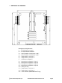
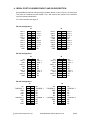
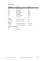
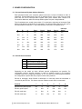
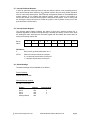
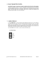
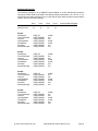
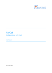
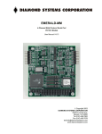
EMERALD-MM User Manual
4-Channel Multi-Protocol Serial Port PC/104 Module
Rev F.00: October 2013
Copyright 2013
DIAMOND SYSTEMS CORPORATION
555 Ellis Street
Mountain View, CA 94043
Tel (650) 810-2500
Fax (650) 810-2525
[email protected]
www.diamondsystems.com
TABLE OF CONTENTS
1.
DESCRIPTION ..................................................................................................................................... 3
2.
FEATURES ........................................................................................................................................... 3
3.
EMERALD-MM BOARD DRAWING ............................................................................................... 4
4.
SERIAL PORT I/O HEADER PINOUT AND PIN DESCRIPTION ............................................... 5
5.
BOARD CONFIGURATION ............................................................................................................... 7
6.
RS-485 TRANSMITTER CONTROL............................................................................................... 10
7.
1-WIRE INTERFACE ........................................................................................................................ 10
8.
INSTALLING EMERALD-MM IN WINDOWS NT ...................................................................... 11
9.
SPECIFICATIONS ............................................................................................................................. 13
2013 Diamond Systems Corp.
Emerald-MM User Manual Revision F.00
Page 2
EMERALD-MM
4-Channel Multi-Protocol Serial Port PC/104 Module
1. DESCRIPTION
Emerald-MM is a PC/104 format I/O module with 4 serial ports. Its model number and
description are:
EMM-4M-XT
4 ports configurable for RS-232, RS-422, or RS-485
Eight different I/O address combinations can be selected, and 10 different interrupt levels can
be assigned to configure each port, allowing operation as COM1 through COM4 as well as
many other settings. Two I/O headers are provided, with two serial ports on each header. The
board operates on +5V only, eliminating the need for a +12V supply that is often required for
serial port operation.
Emerald-MM is based on the 16C554 quad serial port IC. This device contains 4 identical sets
of registers, one for each port, and is compatible with the standard PC serial port. Each port
contains a 16-byte FIFO. Complete descriptions of these registers may be found in the
Appendix. Most users will not need this programming information, as it is normally handled by
the operating system’s communications software.
2. FEATURES
4 16C550-compatible serial ports with 16-byte FIFOs
RS-232, RS-422, RS-485, and 1-Wire interface capability (depending on the model)
Up to 115.2kbps in standard configuration (460.8kbps available)
8 different I/O address options
10 different interrupt level options (using 16-bit PC/104 bus extension)
I/O lines are short circuit protected
Dual 20-pin I/O headers, 2 ports per header
+5V only operation
o
o
Extended temperature (-40 C to +85 C) operation
2013 Diamond Systems Corp.
Emerald-MM User Manual Revision F.00
Page 3
3. MECHANICAL DRAWING
Description of Key Elements
J1
J2
J3
J4
J5
J6
J7
J8
J9
J10
J11
J12
J13
J14
J16
PC/104 8-bit bus connector
PC/104 16-bit bus connector
User I/O header for serial ports 1 and 2
User I/O header for serial ports 3 and 4
Configuration for serial port 1
Configuration for serial port 2
I/O address configuration
Interrupt level configuration for port 1
Interrupt level configuration for port 2
Interrupt level configuration for port 3
Interrupt level configuration for port 4
Factory use only
Configuration for serial port 3
Configuration for serial port 4
1-Wire interface (Model EMM-1W-XT only)
2013 Diamond Systems Corp.
Emerald-MM User Manual Revision F.00
Page 4
4. SERIAL PORT I/O HEADER PINOUT AND PIN DESCRIPTION
Emerald-MM provides two identical 20-pin headers labeled J3 and J4 for the 4 serial ports.
Two ports are contained on each header. Pin 1 and numbers are marked on the board for
connector polarity identification.
For 1-Wire interface see page 10.
RS-232 Configuration:
J3
DCD 1
RXD 1
TXD 1
DTR 1
GND
DCD 2
RXD 2
TXD 2
DTR 2
GND
1
3
5
7
9
11
13
15
17
19
J4
2
4
6
8
10
12
14
16
18
20
DSR 1
RTS 1
CTS 1
RI 1
NC
DSR 2
RTS 2
CTS 2
RI 2
NC
DCD 3
RXD 3
TXD 3
DTR 3
GND
DCD 4
RXD 4
TXD 4
DTR 4
GND
1
3
5
7
9
11
13
15
17
19
2
4
6
8
10
12
14
16
18
20
DSR 3
RTS 3
CTS 3
RI 3
NC
DSR 4
RTS 4
CTS 4
RI 4
NC
2
4
6
8
10
12
14
16
18
20
NC
TXD- 3
RXD- 3
NC
NC
NC
TXD- 4
RXD- 4
NC
NC
RS-422 Configuration:
J3
NC
TXD+ 1
GND
RXD+ 1
GND
NC
TXD+ 2
GND
RXD+ 2
GND
1
3
5
7
9
11
13
15
17
19
J4
2
4
6
8
10
12
14
16
18
20
NC
TXD- 1
RXD- 1
NC
NC
NC
TXD- 2
RXD- 2
NC
NC
NC
TXD+ 3
GND
RXD+ 3
GND
NC
TXD+ 4
GND
RXD+ 4
GND
1
3
5
7
9
11
13
15
17
19
RS-485 Configuration:
J3
NC
TXD/RXD+ 1
GND
NC
GND
NC
TXD/RXD+ 2
GND
NC
GND
1
3
5
7
9
11
13
15
17
19
J4
2
4
6
8
10
12
14
16
18
20
2013 Diamond Systems Corp.
NC
TXD/RXD- 1
NC
NC
NC
NC
TXD/RXD- 2
NC
NC
NC
NC
TXD/RXD+ 3
GND
NC
NC
NC
TXD/RXD+ 4
GND
NC
NC
1
3
5
7
9
11
13
15
17
19
2
4
6
8
10
12
14
16
18
20
Emerald-MM User Manual Revision F.00
NC
TXD/RXD- 3
NC
NC
NC
NC
TXD/RXD- 4
NC
NC
NC
Page 5
Signal Definitions:
Signal Name
RS-232:
DCD
DSR
RXD
RTS
TXD
CTS
DTR
RI
Definition
Direction
Data Carrier Detect
Data Set Ready
Receive Data
Request To Send
Transmit Data
Clear To Send
Data Terminal Ready
Ring Indicator
Input
Input
Input
Output
Output
Input
Output
Input
RS-422:
TXD+, TXDRXD+, RXD-
Differential Transmit Data
Differential Receive Data
Output
Input
RS-485:
TXD/RXD+
TXD/RXD-
Differential Transmit/Receive +
Differential Transmit/Receive -
Bi-directional
Bi-directional
Common to all protocols:
GND
Ground
NC
Not Connected
2013 Diamond Systems Corp.
---
Emerald-MM User Manual Revision F.00
Page 6
5. BOARD CONFIGURATION
5.1 Port and Interrupt Register Address Selection
Each peripheral board in the computer system must have a unique I/O address or block of
addresses. Emerald-MM actually uses five I/O address blocks: one for each of the four serial
ports and one for the interrupt status register. Each port’s address block consists of 8
consecutive addresses, while the interrupt status register occupies a single address.
The I/O addresses are set with jumper block J7, located at the right edge of the board. Eight
different I/O address combinations are selectable. The address shown below for each port is
the base address of that port, i.e. the lowest address of the port’s I/O address block.
A
B
C
Port 1
Port 2
Port 3
Port 4
Interrupt
Status
In
In
In
3F8
2F8
3E8
2E8
220
Out
In
In
3E8
2E8
3A8
2A8
220
In
Out
In
380
388
288
230
224
Out
Out
In
240
248
260
268
224
In
In
Out
100
108
110
118
240
Out
In
Out
120
128
130
138
244
In
Out
Out
140
148
150
158
248
Out
Out
Out
160
168
170
178
24C
5.2 Serial Protocol Selection
J5:
Port 1 protocol configuration
J6:
Port 2 protocol configuration
J13:
Port 3 protocol configuration
J14:
Port 4 protocol configuration
Depending on the model you have, different protocol configurations are possible. For
configurable versions, protocol selection is made by installing jumpers in the positions
indicated below in the configuration headers J5, J6, J13, and J14. For fixed protocol versions,
the configuration is preset with wire jumpers in these same positions.
RS-422 is full-duplex, while RS-485 is half-duplex. In multi-drop mode the transmitter is
controlled by the RTS line. This feature requires software control and is not automatic.
Protocol
1
2
3
4
5
6
Out
In
Out
Out
In
Out
RS-422, point to point
In
Out
In
Out
Out
Out
RS-422, multi-drop
In
Out
In
Out
Out
In
RS-485, multi-drop
In
Out
Out
In
Out
In
RS-232 DTE, point to point
2013 Diamond Systems Corp.
Emerald-MM User Manual Revision F.00
Page 7
5.3 Configuration for RS-422 and RS-485 Modes
When RS-422 or RS-485 modes are selected, not all signals are used by the line drivers and
receivers. Depending on your software configuration, you may need to force some inputs true
so that your software will operate correctly. Jumper blocks J5, J6, J13, and J14 provide a
means to force the input signals true (connect them to ground, or logic 0) for ports 1 – 4,
respectively. The signals that can be controlled in this fashion are CTS, DCD, DSR, and RI.
To force an input signal true on a port, install a jumper next to that signal’s name on the
corresponding header for that port. Jumpers should not be installed in these locations for RS232 operation.
NOTE: The positions TX and RX are not used for this purpose. Installing jumpers in these
locations has an entirely different meaning. See Cable Endpoint Termination below.
5.4 RS-422 / RS-485 Cable Endpoint Termination
In RS-422 or RS-485 networks, termination resistors are normally installed at the endpoints of
the cables to minimize reflections on the lines. Emerald-MM provides 120 resistors for this
purpose. To enable resistor termination, install jumpers in the locations TX and RX of J5, J6,
J13, or J14 (for ports 1 – 4, respectively). Termination is only needed, and should only be
used, at the cable endpoints. Installing termination resistors at additional points in the network
may cause overloading and failure of the line drivers due to the lower impedance caused by
multiple resistors in parallel.
5.5 Interrupt Levels
J8:
Port 1 interrupt configuration
J9:
Port 2 interrupt configuration
J10:
Port 3 interrupt configuration
J11:
Port 4 interrupt configuration
Each serial port requires an interrupt level as well as a base I/O address. Four jumper blocks,
J8 through J11, are provided to select the interrupt level for each port from among levels 2, 3,
4, 5, 6, 7, 10, 11, 12, and 15. Install a jumper in the position corresponding to the desired
interrupt level for each port.
Note: Interrupt levels 2 – 7 are available on the standard 8-bit PC/104 bus header J1. If you
are using an 8-bit bus, these are the only levels available to you. Interrupt levels 10, 11, 12,
and 15 are available on the 16-bit PC/104 bus extension header J2. If you are using a 16-bit
bus, then all 10 levels are available to you. Also, on a system with a 16-bit bus, interrupt level
2 is rerouted to level 9.
5.6 Interrupt Sharing
On the PC/104 bus, interrupt levels may be shared by multiple devices. For this reason, the
interrupt is driven to a logic high level by the device requesting service, and when the device
is serviced it tri-states the line rather than driving it low. This technique avoids contention by
two devices trying to drive the line with opposing logic levels.
2013 Diamond Systems Corp.
Emerald-MM User Manual Revision F.00
Page 8
5.7 Interrupt Pulldown Resistor
In order to guarantee valid logic levels on the line when the device is not requesting service,
each active interrupt level requires a 1K pulldown resistor. Only one such resistor should be
used on each active interrupt line. Each interrupt configuration header on Emerald-MM has a
position marked “R” for enabling the pulldown resistor. Install a jumper in this position to
connect the resistor, and remove the jumper to disconnect the resistor. If two or more ports
are sharing the same interrupt level, install the jumper in the R position for any one of the
ports and leave it off the others.
5.8 Interrupt Status Register
The interrupt status register indicates the status of each port’s interrupt request line. It
operates regardless of whether interrupt sharing is enabled (see below). If two or more ports
are sharing the same interrupt level, the status register will still indicate the correct status of
each port’s interrupt request line.
Bit No.
7
6
5
4
3
2
1
0
Name
X
X
X
X
INT4
INT3
INT2
INT1
Definitions:
X
Bit not used; generally reads back as a 1
INT4-1
Status of interrupt request for each port:
0 = no interrupt request active for this port
1 = interrupt request active for this port
5.9 Default Settings
The default settings for Emerald-MM are as follows:
Protocol settings:
All ports set for RS-232
Address/Interrupt settings:
(J7 A B C = In In Out):
Feature
Port 1
Port 2
Port 3
Port 4
Interrupt Status
Address
100
108
100
108
240
2013 Diamond Systems Corp.
Interrupt level
3
3
3
3
Emerald-MM User Manual Revision F.00
Page 9
6. RS-485 TRANSMITTER CONTROL
In an RS-485 network, the same pair of wires is used for both transmit and receive signals.
Although any number of nodes can be listening simultaneously, only one can be transmitting
or have its transmitter turned on in order for valid data to be transmitted across the network.
On Emerald-MM, an RS-485 port’s transmitter enable signal is controlled by that port’s RTS
signal. The RTS signal must be asserted (driven low) to enable the transmitter and
deasserted (driven high) to turn off the transmitter.
7. 1-WIRE INTERFACE
In model EMM-1W-XT, a 1-Wire interface module (HA7S from Point Six, Inc.) is mounted on
the board near the top edge. This port converts the RS-232 signals from port 1 into 1-Wire
signals. The user connections for port 1 are made through a separate 4-pin header J16 on
the right side of the board. The port 1 signals on pins 1-10 of J3 may not be used because of
conflicts with the RX line being driven by the 1-Wire interface module.
On model EMM-1W-XT, Ports 2, 3, and 4 are fixed in RS-232 mode.
J16 1-Wire Pinout
1
+5
2
Gnd
3
1-Wire
4
Gnd
2013 Diamond Systems Corp.
Emerald-MM User Manual Revision F.00
Page 10
8. INSTALLING EMERALD-MM IN WINDOWS NT
1. Run REGEDT32.EXE and go to the following dialog box:
Key_Local_Machine \ System \ CurrentControlSet \ Service \ Serial \ Parameters
2. Add a new key for each serial port by selecting Edit \ Add Key. The following parameters
need to be specified for each serial port:
SerialN (N = serial port number, 1, 2, 3, 4, etc.):
Parameter
DosDevices
ForceFifoEnable
Interrupt
Type
REG_SZ
REG_DWORD
REG_DWORD
InterruptStatus
REG_DWORD
PortAddress
PortIndex
REG_DWORD
REG_DWORD
SharedInterrupts
REG_DWORD
Value, Comments
Name of port, e.g. COM5, COM6
0x1 for yes
IRQ level in Hex format, e.g. 0x5 for 5 or 0xa for
10
Address of interrupt status register in Hex, e.g.
0x224
Address or port in Hex, e.g. 0x120 for Hex 120
Bit position in status register: 0x1 for LSB
through 0x4
0x1 for yes, 0x0 for no
3. Exit REGEDT32.EXE and restart NT.
See the example on the following page.
2013 Diamond Systems Corp.
Emerald-MM User Manual Revision F.00
Page 11
Windows NT Example
The following example is for an EMM-XT board installed on a CPU that already contains 2
serial ports called COM1 and COM2. The address setting combination is A out, B in, C out,
and all ports are sharing interrupt level 12. Note that all ports share the same interrupt status
register, but the bit position changes.
Address
Interrupt Level
Port 1
0x120
12
Port 2
0x128
12
Port 3
0x130
12
Serial3:
DosDevices
ForceFifoEnable
Interrupt
InterruptStatus
PortAddress
PortIndex
SharedInterrupts
REG_SZ
REG_DWORD
REG_DWORD
REG_DWORD
REG_DWORD
REG_DWORD
REG_DWORD
COM3
0x1
0xc
0x244
0x120
0x1
0x1
Serial4:
DosDevices
ForceFifoEnable
Interrupt
InterruptStatus
PortAddress
PortIndex
SharedInterrupts
REG_SZ
REG_DWORD
REG_DWORD
REG_DWORD
REG_DWORD
REG_DWORD
REG_DWORD
COM4
0x1
0xc
0x244
0x128
0x2
0x1
Serial5:
DosDevices
ForceFifoEnable
Interrupt
InterruptStatus
PortAddress
PortIndex
SharedInterrupts
REG_SZ
REG_DWORD
REG_DWORD
REG_DWORD
REG_DWORD
REG_DWORD
REG_DWORD
COM5
0x1
0xc
0x244
0x130
0x3
0x1
Serial6:
DosDevices
ForceFifoEnable
Interrupt
InterruptStatus
PortAddress
PortIndex
SharedInterrupts
REG_SZ
REG_DWORD
REG_DWORD
REG_DWORD
REG_DWORD
REG_DWORD
REG_DWORD
COM6
0x1
0xc
0x244
0x138
0x4
0x1
2013 Diamond Systems Corp.
Port 4
0x138
12
Interrupt Status Register
0x244
Emerald-MM User Manual Revision F.00
Page 12
9. SPECIFICATIONS
Serial Port Specifications
No. of serial ports:
Protocol:
Maximum baud rate:
Communications parameters:
Short circuit protection:
4
RS-232, RS-422, RS-485
Jumper selected or fixed, depending on the version
115kbps standard version
460.8kbps available (-HS option)
5, 6, 7, or 8 data bits; Even, odd, or no parity
All outputs protected against continuous short circuit
RS-232 mode:
Input impedance:
3K
min
Input voltage swing:
30V max
Output voltage swing:
5V min, 7V typical
RS-422, RS-485 modes:
Differential input threshold:
-0.2V min, +0.2V max
Input impedance:
Input current:
12K min
+1.0mA max (VIN = 12V)
-0.8mA max (VIN = -7V)
Differential output voltage:
High/low states differential
output voltage symmetry:
2.0V min (RL = 50 )
0.2V max
General Specifications
I/O header:
Dimensions:
Power supply:
Current consumption:
Operating temperature:
Operating humidity:
PC/104 bus:
2013 Diamond Systems Corp.
2 20-position (2x10) .025” square pin header on .1” centers;
Headers mate with standard ribbon cable (IDC) connectors
3.55” x 3.775” (PC/104 standard)
+5VDC 10%
80mA typical, all outputs unloaded
o
o
-40 C to +85 C standard
5% to 95% noncondensing
8-bit and 16-bit bus headers are installed and used (16-bit
header is used for interrupt levels only)
Emerald-MM User Manual Revision F.00
Page 13