1
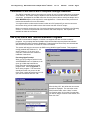
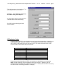
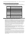
Trace Engineering SW Communication Adapter Owner’s Manual
Ver 1.2
PN 2978
11/12/98
Page 1
Introducing the SWCA
The SWCA (Sine Wave Communications Adapter) allows any SW series inverter / charger to be
connected to a computer serial port or directly to a modem to be controlled and monitored over
long distances.
The SWCA package includes the following items:
•
SWCA adapter (gray plastic housing with green LED, phone jack and a 25 pin
connector)
•
Serial Port Adapter (black plastic housing with phone jack and 9 pin conector)
•
25 foot, 4 conductor phone cable (with RJ11 jack tabs on the same side of the cable)
•
3.5” floppy disk with DOS program SWCPS.EXE (simulates the inverters control
panel)
•
Instructions / Owners Manual
Please be sure all of these parts are included before trying to use the SWCA.
Installing the SWCA
The SWCA converts the REMOTE port on the SW series inverter / charger into a standard RS232
type communications port interface. The installation is very simple.
Connect the SWCA adapter to the SW series inverter / charger’s REMOTE CONTROL port
located on the left end of the inverter, near the AC wiring compartment. Note that there are two
ports located here – on is used for the stacking cable and the other is the remote control port.
Make sure you connect the SWCA to the correct port. If a SW series remote control is being
used, it will have to be disconnected while the SWCA is in use.
Connect the phone cable to the phone jack on the gray SWCA housing and to the black serial port
adapter. Plug the serial port adapter into the computers serial port. On some computers, a DB9
to DB25 adapter may be needed to allow connection.
Connecting Multiple SWCAs to a Single Computer
Up to eight SWCA can be used with a single computer serial port. The phone cable four
conductors are simply paralleled together using standard phone cable line “splitters”. The splitters
must connect the wires of the same color together – not switch the colors around. Contact your
local telephone supply company for these adapters.
Before connecting multiple adapters to a serial port, connect each adapter individually to ensure
operation. The adapters must have their ID number changed by using the DOS program provided
on the disk before they are connected to the same computer serial port. The ID number can only
be changed with a single adapter connected to the computer’s serial port.
Installing the SWCPS DOS Program
A control panel simulation software program is included on the floppy disk allows a IBM
compatible personal computer to operate as a virtual control panel for up to eight SW series
inverter / chargers. For other computer platforms, see the section “Use of the SWCA adapter
with Terminal Emulation Programs”
To install the software, insert the 3.5” floppy disk into your computer floppy drive and copy the file
“SWCPS.EXE” from the floppy to your hard disk. Note the location of the file on your hard disk for
later reference. Alternately, you can run the program from the floppy disk directly.
Trace Engineering SW Communication Adapter Owner’s Manual
Ver 1.2
PN 2978
11/12/98
Page 2
Using the SWCPS DOS Program
To start the SWCPS (SW series control panel simulator) program, simple double click on the file
“SWCPS.EXE”. The program can also be started under a MSDOS window by typing SWCPS in
the directory which you copied the file into.
When the program starts, you will see a line drawing of the SW series control panel on the
computer screen. You can resize the MSDOS window to allow better viewing of the control panel
if the labeling is not clear.
Once the program has started, it will look for an SWCA programmed with an ID number of 1. This
is the default ID number of all adapters. If two adapters are connected to a PC with the same ID
number, you will not be able to communicate with either. The program also assumes that the
SWCA will be connected to a serial port with a COM number of 1. If you are using a COM port
other than one, refer to the following section “ Changing the COM Port Number”.
On the virtual control panel simulation, the buttons of the real control panel have been replaced
with labels shown as “F1” through “F10”. These refer to the function keys of the computer’s
keyboard which are located either above or next to the main keyboard area. Each function key is
listed under a specific inverter operation. Pressing the appropriate function key causes the display
on both the inverter and the PC screen to change accordingly.
Also shown on the virtual control panel is the LCD display window on the inverter’s control panel.
This will show the same information that is available at the inverter. When no adapter is available,
the text “ADAPTER OFFLINE” will appear. When an SWCA has been successfully connected
to, the LCD display window of the control panel simulator will show what is displayed on the
inverter’s LCD display.
To the right of the LCD display area on the control panel simulator is an area where the status of
the inverter’s LED indicators are displayed. Any active LEDs are displayed by the label
description of the LEDs function being shown. If the LED is flashing on the inverter, than the
label description of the LED will also flash on the control panel simulator.
Since the same menu system is used with the control panel simulator as used on the inverter
itself, the operation of the SWCA will be familiar to anyone who has programmed a SW series
inverter / charger system. The only difference is the use of the function keys instead of the
buttons.
Changing the PC’s COM Port Number
To change the COM port number that the control panel simulator DOS program uses to find the
adapter, add the COM port ID number (1-4) after the DOS command used to start the SWCPS
program as follows:
C:> SWCPS 2
This command will cause the program to look at the COM 2 port on the PC for the SWCA
adapters.
Trace Engineering SW Communication Adapter Owner’s Manual
Ver 1.2
PN 2978
11/12/98
Page 3
Accessing HELP Information from the SWCPS Program
A help screen is available while using the SWCPS program. It is accessed by pressing the F10
key on the computer’s keyboard.
To leave the help screen, press the ESC key to return you to control panel simulation program.
Accessing the SETUP MENU from the SWCPS Program
To access the inverter’s SETUP MENU while using the SWCPS program, press and hold the
ALT key and then the hit the F8 key at the same time. This feature is only used with inverters
having Rev 4.01 and higher software versions.
To leave the SETUP MENU, press the F7 button, which returns you to the SET INVERTER main
menu display.
Accessing the SWCA PROGRAMMING MENU
To access the inverter’s SWCA’s programming menu while using the SWCPS program, press
and hold the ALT key and then the hit the P key at the same time.
Pressing the F1 key allows the SWCA’s ID number to be changed from the default of 1 to any
number up to 8. After changing the ID number, write the adapters new ID number on the outside
of the adapters gray housing to make later identification of the adapter easier.
Pressing F2 allows the adapter’s configuration code to be changed. This alters the operation of
the adapter. Do not change this code from the default value of “06” unless instructed by Trace
Engineering.
Pressing F3 allows the customer to enter any text string to allow later identification of the adapter.
Simply type in the information desired and hit return.
To leave the programming menu, press the ESC key, which returns you to the previous inverter
display.
If an adapter is not found, the program will indicate a TIMEOUT ERROR. Check the adapter and
cable for proper connection and retry the program.
Switching Between Multiple SWCA adapters / inverters
To select another inverter, simply press the number key for the SWCA adapter that was
programmed in and written on the outside of the adapter as previously discussed. Any number
from 1 though 8 is acceptable.
Exiting the SWCPS Program
To exit the SWCPS program, press and hold the ALT key and then the hit the X key at the same
time. You can also use the ESC key to quit as well.
Trace Engineering SW Communication Adapter Owner’s Manual
Ver 1.2
PN 2978
11/12/98
Page 4
Connection of the SWCA with a Computer through a Modems
The SWCA is capable of direct connection to a modem for use in remote sights where a computer
is not desired. The modem must be capable of auto answer and needs to be set for 9600 baud
connection. An adapter for the DB9 connection from the phone cable to serial port adapter and a
NULL MODEM adapter will be required for most applications. Contact the modem provider and
modem documentation for more information.
You might need the modem at the inverter location to be DC powered if you need to connect to
the inverter during a fault condition where the inverter has shut off its AC output.
Modem connection requires the use of a terminal emulation program as described in the following
sections. A modem is required both at the inverters and at the computer, with a phone line
available to make the connection.
Use of the SWCA with Terminal Emulation Programs
The SW Communications Adapter, or SWCA, now supports use with “terminal emulation”
programs. Any computer that has available serial communications port and terminal software
(like Windows 95 HyperTerminal or DataStorm Technologies ProComm Plus) can communicate
with the SW series inverter via a cable or modem connection.
This section will help you connect to the SWCA using Win95’s HyperTerminal. This program is
usually installed with Windows 3.1, 95
and NT systems. If it is not on your
computer, consult the user manual for
installation instructions.
Executing HyperTerminal:
When you click on HyperTerminal in the
ACCESSORIES menu of Windows, it will
open up a folder that has different
HyperTerminal configurations and the
program itself. Click on Hypertrm, or ,
which is the program. The first screen
should be like the one you see on the
right. Enter a name and select an icon for
your new connection and click “OK”.
After clicking “OK”, this will be the next screen
that will be displayed. For connection to the
SWCA with a cable, select “direct” connect.
On Connect using, click on the Com port that
you will be using to connect to the SWCA, and
then click “OK”.
Trace Engineering SW Communication Adapter Owner’s Manual
Ver 1.2
PN 2978
11/12/98
Page 5
This is the last screen to be displayed. The
port settings need to be as follows:
9600,8,N,1 OR 9600 Baud, 8 Data bits,
No or None Parity, and 1 Stop bit.
No other settings will work other than these.
The flow control can be either setting.
Click “OK” and you should get a blank
terminal window.
LED Indicator Codes
In order to test the SWCA, it must be plugged in to an inverter that is powered up on batteries or a
suitable power supply. Press the number “1”. If everything is correct, the inverter should reply
with a “UNIT1” and possibly some two character codes. The codes indicate the status of the
inverter’s LEDs. The two letter codes are as follows:
Abbreviation
IN
LT
A1
A2
BK
FL
ER
OC
Meaning
Inverting
Line Tie
AC1 IN
AC2 IN
Bulk
Float
Error
Over Current
If there are no codes, then either no LED’s are currently on or the adapter is not responding.
Note: If a LED is flashing, it may not appear each time you pressed “1” because it was not
illuminated when the SWCA sent the data to the computer. A flashing LED should be indicated by
the LED two letter code being repeated on the display.
Trace Engineering SW Communication Adapter Owner’s Manual
Ver 1.2
PN 2978
11/12/98
Page 6
Keyboard Commands When Used with Terminal Programs
There are a few keystrokes that you need to remember when working with the SWCA and
terminal software. These keystrokes will enable you to navigate the menus and make changes to
the settings. The keystrokes and there meaning are as follows:
Keystroke
1 thru 8
L
R
U
D
– or _
+ or =
I
G
<Ctrl><S>
? or /
V
T
Function
Select inverter – 1 thru 8 is the adapter’s ID number, 1
is default. You must set the others using the DOS
program with only one adapter connected at a time.
Menu Headings – or Left
Menu Headings + or Right
Menu Item – or Up towards top
Menu Item + or Down towards bottom
Set Point – (lower value)
Set Point + (higher value)
Inverter On/Off Menu (same as the Red button on the
inverter control panel) Rotates through the options
Generator On/Off Menu (same as the Green button on
the inverter control panel) Rotates through the options
Enter Setup Menu (Same as pushing Generator and
On/Off Menu at the same time) Allows adjustments
Status of the LED shown on the front of the inverter
Software Version number of SWCA
Set Terminal Mode – If you see lots of strange
characters displayed, try pressing T for Terminal
mode. Changes all of the data to normal ASCII form
Troubleshooting if No Response comes from the SWCA
If you pressed “1” and nothing happened, then check your settings. Are you selecting the correct
COM port? Did you set it for 9600 Baud? If these answers are yes, then try pressing number “2”.
Did this work? If not, try closing HyperTerminal, say YES to saving your session. Disconnect the
adapter and plug it back in, making sure the phone cord is securely plugged in. When you plug in
the SWCA, the green LED on the adapter should light up. Go to the HyperTerminal program
again, but now open your saved session. It should have the name and icon you choose for it.
If the LED turns off when the cable is connected, check the cable for proper orientation of the
phone jacks. They must be crimped onto the phone cable with the small tabs located on the
same side of the cable. If the cable is not correct, replace it with another one. This is the
standard phone cable orientation.
Also try tightening the two small screws located on the SWCA into the stand-offs on the
connectors of the inverters. Also connect the thumb screws on the adapter for the phone cable to
the serial port. After tightening the screws, retest the adapter. If it still does not respond, try
using the DOS software provided with the SWCA.
With the DOS software, only have on adapter connected. Once the program has started, to
access the “programming” menu press and hold the ALT key and then hit the P key at the same
time. Check the adapter’s address number and configuration code. Reset if needed and retry
with Hyperterminal program.
Be sure that the phone cable is the correct type. The small clip on the crimped on jacks must be
located on the same side of the cable or it will cause garbled characters or no communication.
If multiple adapters are connected, disconnect them and try each individually with a single cable
and no adapters or splitters in the cable. Confirm that the cable is correct type. Make sure the
adapter is plugged into the remote port and not the stacking port. Try the adapter on another
computer or inverter.