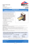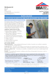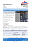
1
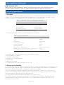
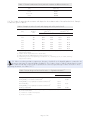
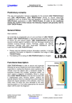
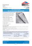
APPROVAL INSPECTION TESTING CERTIFICATION Kingspan Insulation Ltd Pembridge Leominster Herefordshire HR6 9LA Tel: 01544 388 601 Fax: 01544 388 888 TECHNICAL APPROVALS FOR CONSTRUCTION Agrément Certificate 10/4798 e-mail: [email protected] website: www. insulation.kingspan.com Product Sheet 1 KINGSPAN KOOLTHERM INSULATION KOOLTHERM K17 AND K18 INSULATED DRY LINING SYSTEMS PRODUCT SCOPE AND SUMMARY OF CERTIFICATE This Certificate relates to Kooltherm K17 and K18 Insulated Dry Lining Systems, comprising Kooltherm rigid phenolic boards bonded to plasterboard, for use as an insulating dry lining to masonry walls and the underside of timber or steel rafters in pitched roofs, in existing and new dwellings and buildings of similar occupancy. Kooltherm K17 is installed using plaster dabs or proprietary adhesive bonding or mechanical fixings if fixed on metal furring systems or timber battens. The Kooltherm K18 is fixed only by mechanical fixings. AGRÉMENT CERTIFICATION INCLUDES: • factors relating to compliance with Building Regulations where applicable • factors relating to additional non-regulatory information where applicable • independently verified technical specification • assessment criteria and technical investigations • design considerations • installation guidance • regular surveillance of production • formal three-yearly review. KEY FACTORS ASSESSED Thermal performance — the systems can contribute to limiting heat loss through walls and roofs and the U values achieved will depend on the overall construction and insulation thickness (see section 5). Condensation — the systems can limit the risk of surface condensation and the risk of interstitial condensation should be assessed for each case (see section 6). Behaviour in relation to fire — the boards have a classification of B-s1,d0 to BS EN 13501-1 : 2002 (see section 8). Durability —under normal conditions, the boards are rot-proof, dimensionally stable and durable (see section 13). The BBA has awarded this Agrément Certificate to the company named above for the systems described herein. These systems have been assessed by the BBA as being fit for their intended use provided they are installed, used and maintained as set out in this Certificate. On behalf of the British Board of Agrément Date of First issue: 30 November 2010 Simon Wroe Head of Approvals — Physics Greg Cooper Chief Executive The BBA is a UKAS accredited certification body — Number 113. The schedule of the current scope of accreditation for product certification is available in pdf format via the UKAS link on the BBA website at www.bbacerts.co.uk Readers are advised to check the validity and latest issue number of this Agrément Certificate by either referring to the BBA website or contacting the BBA direct. British Board of Agrément Bucknalls Lane Garston, Watford Herts WD25 9BA ©2010 Page 1 of 12 tel: 01923 665300 fax: 01923 665301 e-mail: [email protected] website: www.bbacerts.co.uk Regulations In the opinion of the BBA, Kooltherm K17 and K18 Insulated Dry Lining Systems, if used in accordance with the provisions of this Certificate, will meet or contribute to meeting the relevant requirements of the following Building Regulations: The Building Regulations 2010 (England and Wales) Requirement: B2(1) Internal fire spread (linings) Comment: Requirement: B3(4) Internal fire spread (structure) Comment: Requirement: C2(c) Resistance to moisture Comment: Requirement: L1(a)(i) Conservation of fuel and power The systems are unrestricted under this Requirement. See section 8.1 of this Certificate. The systems can contribute to a construction satisfying this Requirement. See section 8.3 of this Certificate. The systems can contribute to meeting this Requirement. See sections 6.1 and 6.5 of this Certificate. Comment: The systems can contribute to a building meeting this requirement. See sections 5.3 and 5.4 of this Certificate. Requirement: Regulation7 Materials and workmanship Comment: The systems are acceptable. See section 13 and the Installation part of this Certificate. The Building (Scotland) Regulations 2004 (as amended) Regulation: 8(1)(2) Fitness and durability of materials and workmanship Comment: Regulation: Standard: 9 2.4 Building standards — construction Cavities The systems are acceptable. See sections 12 and 13 and the Installation part of this Certificate. The systems can contribute to a construction satisfying this Standard, with reference to clause 2.4.2(1). See section 8.3 of this Certificate. Comment: Standard: 2.5 Standard: 3.15 6.1(b) 6.2 Carbon dioxide emissions Building insulation envelope The systems can contribute to satisfying clauses or parts of 6.1.1(1), 6.1.2(1), 6.1.3(1), 6.1.6(1), 6.2.1(1), 6.2.3(1), 6.2.4(1), 6.2.9(1), 6.2.11(1) of these Standards. See sections 5.3 and 5.4 of this Certificate. Comment: Regulation: Condensation The systems can contribute to satisfying this Standard, with reference to clauses 3.15.1(1), 3.15.4(1) and 3.15.5(1). See sections 6.1 and 6.6 of this Certificate. Comment: Standard: Standard: Internal linings The systems are unrestricted under this Standard, with reference to clause 2.5.1(1). See section 8.1 of this Certificate. Comment: 12 Building standards — conversions All comments given for these systems under Regulation 9, also apply to this Regulation, with reference to clause 0.12.1(1) and Schedule 6(1). Comment: (1) Technical Handbook (Domestic). The Building Regulations (Northern Ireland) 2000 (as amended) Regulation: B2 Fitness of materials and workmanship Comment: Regulation: B3(2) Suitability of certain materials Comment: Regulation: C5 Condensation Comment: Regulation: E3 Internal fire spread — Linings Comment: Regulation: E4(4) Internal fire spread — Structure Comment: Regulation: Regulation: F2(a)(i) F3(2) Conservation measures Target carbon dioxide Emissions Rate Comment: The systems are acceptable. See section 13 and the Installation part of this Certificate. The systems are acceptable. See section 12 of this Certificate. The systems can contribute to satisfying this Regulation. See section 6.1 of this Certificate. The systems are unrestricted under this Regulation. See section 8.1 of this Certificate. The systems can contribute to a construction satisfying this Regulation. See section 8.3 of this Certificate. The systems can contribute to a building meeting this Regulation. See sections 5.3 and 5.4 of this Certificate. Construction (Design and Management) Regulations 2007 Construction (Design and Management) Regulations (Northern Ireland) 2007 Information in this Certificate may assist the client, CDM co-ordinator, designer and contractors to address their obligations under these Regulations. See section: 2 Delivery and site handling (2.4) of this Certificate. Page 2 of 12 Non-regulatory Information NHBC Standards 2010 NHBC accepts the use of Kooltherm K17 and K18 Insulated Dry Lining Systems, when installed and used in accordance with this Certificate, in relation to NHBC Standards, Chapter 8.2 Wall and ceiling finishes. Technical Specification 1 Description 1.1 Kooltherm K17 and K18 Insulated Dry Lining Systems consist of plasterboard, facings and insulation as shown in Table 1. K17 is installed by using plaster dabs and nailable plugs or proprietary adhesive bonding or can be mechanically fixed (see the Installation part of this Certificate). K18 is mechanically fixed. Table 1 Components of the two insulating dry lining boards Kooltherm K17 Kooltherm K18 Plasterboard Plasterboard(1) Composite foil facing Composite foil facing Phenolic insulation Phenolic(2) insulation Coated glass tissue facing Composite foil facing (1) (2) (1) The plasterboard component is manufactured in accordance with BS EN 520 : 2004. (2) Manufactured in accordance with BS EN 13166 : 2008. 1.2 The board is available with the nominal characteristics shown in Table 2. Table 2 Nominal characteristics Length 2400 mm Width 1200 mm Insulation thickness 20 mm to 80 mm Nominal density of insulation 35 kg·m–3 Thickness of plasterboard 12.5 mm Weight of plasterboard 24 kg Edge profile of the insulated dry lining Square and tapered edged Minimum compressive strength for the insulation at 10% compression 125 kPa The overall water vapour resistance(1) of the Kooltherm > 100 MN·s·g–1 (1) For condensation risk analysis, refer to the resistance values of each component of the Kooltherm K17 or K18 as per Table 9 in section 6. 1.3 Ancillary items, which are outside the scope of this Certificate, include: • dry lining adhesive compound • metal studs or timber battens • dry wall screws or plasterboard nails • nailable plugs • edge and corner beads • scrim tape and joining compound or plaster for skim coat. 2 Delivery and site handling 2.1 The boards are delivered to site shrink-wrapped in polythene on pallets. Each board has the manufacturing code printed on the surface and each pack carries a label with the product description and characteristics, manufacturer’s name and the BBA identification mark incorporating the number of this Certificate. 2.2 It is essential that the boards are raised off the ground and stored inside or under cover on a flat, dry, level surface in a well-ventilated area. The boards must be protected from rain, snow and prolonged exposure to sunlight and any that have been allowed to get wet should not be used. 2.3 The boards must not be exposed to a naked flame or other ignition sources. 2.4 The boards can be cut using a fine-toothed saw, or by cutting through the insulation and paper backing of the plasterboard, then snapping the system face down over a straight edge and cutting the paper facing of the plasterboard on the other side. Page 3 of 12 Assessment and Technical Investigations The following is a summary of the assessment and technical investigations carried out on Kooltherm K17 and K18 Insulated Dry Lining Systems. Design Considerations 3 General 3.1 Kooltherm K17 and K18 Insulated Dry Lining Systems are for use as an insulating dry lining board for solid or cavity masonry walls and the underside of timber or steel rafters in pitched roofs of dwellings or buildings of similar occupancy and in non-load bearing partitions. 3.2 The boards are satisfactory for use as an insulating dry lining system for new and existing dwellings or buildings with similar occupancy. They should be installed in accordance with the Certificate holder’s instructions. 3.3 Since insulating dry linings are not intended to offer resistance to rain penetration, walls to be insulated with dry lining must be already rain resistant and show no signs of water ingress. 3.4 It is recommended that services which penetrate the dry lining, eg, light switches and power outlets, are kept to a minimum to limit damage to vapour checks. 3.5 If present, mould or fungal growth should be treated prior to the application of the systems. 3.6 It is essential that proper care and attention is given to maintaining the integrity/continuity of vapour control layers (VCL) (see section 14 of this Certificate). 3.7 De-rating of any electrical cables in areas where the product restricts the flow of air should be considered. Masonry Walls 3.8 The boards may be installed on masonry construction including clay and calcium silicate bricks, concrete blocks, and natural and reconstituted stone blocks. Masonry walls of new buildings should be designed and constructed in accordance with BS 5628-3 : 2005 and BS 8000-3 : 2001. It is essential that such walls are constructed having regard to the local wind-driven rain index. Where reinforced masonry is involved, the design should be in accordance with BS 5628-2 : 2005. 3.9 With dry lining installations that form a void of 20 mm or more (ie timber batten or metal studs systems), services can be incorporated behind the dry lining, making the chasing of the wall unnecessary. Where the services have a greater depth than the void, the wall should be chased rather than the insulation. 3.10 The installation of insulating dry lining systems requires careful detailing around doors and windows to achieve a satisfactory surface for finishing. In addition, every attempt should be made to minimise the risk of thermal bridging at reveals and where heavy separating walls are attached to the external wall. New work must be designed to accommodate the thickness of the dry lining, particularly at reveals, heads, sills and in relation to ceiling height. Where the dimensions of fixtures are critical (eg bathrooms), these should be checked before installation. Pitched Roof 3.11 The pitched roof should be designed and constructed in accordance with BS 5534 : 2003 (see sections 15.6 to 15.10) and incorporate normal precautions against moisture ingress. 3.12 The systems are suitable for use beneath the rafters in conjunction with an approved (BBA or equivalent) breathable membrane and VCL when necessary, in tiled or slated, pitched roofs, designed and constructed as stated in section 3.11. 3.13 New constructions subject to the national Building Regulations should be designed in accordance with the relevant recommendations of BS 5268-2 : 2002 and Eurocode 3. 4 Practicability of installation The systems are designed to be installed by a competent general builder, or a contractor experienced with these types of systems. 5 Thermal performance 5.1 Calculations of thermal transmittance (U value) of a specific construction using insulated dry lining should be carried out in accordance with BS EN ISO 6946 : 2007, BRE Report (BR 443 : 2006) Conventions for U-value calculations and BRE Digest 465, using the declared thermal conductivity ( 90/90 value) for the insulation component as given in Table 3 and a design value of 0.19 W·m–1·K–1 for the plasterboard. Page 4 of 12 Table 3 Thermal conductivities for the phenolic insulation at different thicknesses Thickness, t of insulation (mm) 90/90 values (W·m–1·K–1) t < 25 0.023 25 ≤ t < 45 0.021 t ≥ 45 0.020 Note: For calculation purposes if emissivity value of the composite foil is required, consult the Certificate holder. 5.2 The U value of a typical wall construction will depend on the insulation value of the wall and its finish. Example U values are given in Table 4. Table 4 Example U values for walls and sloping sides of the pitched roofs Board thickness (mm) Phenolic foam thickness (mm) U value for lining to walls (W·m–2·K–1) U value for lining(1)(2) to pitched roofs (W·m–2·K–1) K17(3) K18(4) K17 K18 32.5 20 0.66 0.60 1.0 0.80 42.5 30 0.48 0.49 0.75 0.64 52.5 40 0.39 0.42 0.61 0.53 62.5 50 0.32 0.36 0.51 0.45 72.5 60 0.27 0.32 0.44 0.40 82.5 70 0.24 0.28 0.39 0.35 92.5 80 0.22 0.26 0.34 0.32 (1) Includes fixing correction ≥ 3% (steel fixings – = 50 W·m–1·K–1, 16.66 fixings per m2, d = 4.8mm, and fixings fully penetrates insulation). (2) Includes 150 mm airspace between the 150 mm rafters. (3) Adhesively fixed with nailable plugs but no fixing correction for < 3%. (4) Includes fixing correction ≥ 3% (steel fixings – = 50 W·m–1·K–1, 10.76 fixings per m2, d = 4.8mm, and fixings fully penetrates insulation). 5.3 When considering insulation requirements, designers should refer to the detailed guidance contained in the documents supporting the national Building Regulations. The U values shown in Table 4 indicate that the systems can enable a wall and a sloping side of a pitched roof to achieve typical design U values referred to in those supporting documents. See Tables 5 to 7. Table 5 Mean design roof and wall U values — England and Wales (1) Construction U value (W·m–2·K–1) Roof Wall Existing building – new or replaced wall – 0.28 Existing building – renovated or retained wall(2) – 0.30 Existing building – new, replaced, renovated or retained roof(3) 0.16 – Notional dwelling 0.16 0.35 Existing building – new, replaced, renovated or retained roof(4) 0.18 – Dwelling new-build limit 0.20 0.30 (1) (2) (3) (4) Flexible approaches on existing buildings are given in the Approved Documents. All other wall insulation. Pitched roof – insulation at ceiling level. All other roof insulation. Page 5 of 12 Table 6 Mean design roof and wall U values — Scotland (1) Construction U value (W·m–2·K–1) Roof Wall Notional dwelling 0.13 0.19 New dwelling simplified method 0.13 0.19 Conversion unheated building (into dwellings) 0.13 0.19 Extension to dwelling(2) 0.13 0.19 Conversion of unheated building (into dwellings) 0.15 0.19 Extension to dwelling(3) 0.15 0.19 (2) Alterations and reconstructions to a dwelling 0.15 0.22 Stand-alone building < 50 m to a dwelling (2) 0.15 0.22 Conversion of unheated building 0.15 0.25 (3) Alterations and reconstructions to a dwelling 0.18 0.22 Stand-alone building < 50 m2 to a dwelling(3) 0.18 0.22 New dwelling limit 0.18 0.25 Conversion of heated building 0.25 0.30 (2) (3) 2 (1) Flexible approaches on existing buildings are given in the Technical Handbooks. (2) Pitched roof – insulation at ceiling level. (3) All other roof insulation. Table 7 Mean design roof and wall U values — Northern Ireland (1) Construction U value (W·m–2·K–1) Roof Wall 0.16 – Notional dwelling 0.16 0.35 Existing building – new, replaced, renovated or retained roof(3) 0.20 – Existing building – new, replaced, renovated or retained roof(2) Existing building – new wall Building new-build limit Existing building – replaced, renovated or retained wall (4) (1) (2) (3) (4) – 0.30 0.25 0.35 0.25 0.35 Flexible approaches on existing buildings are given in the Technical Booklets. Pitched roof – insulation at ceiling level. Pitched roof – insulation at rafter level. All other wall insulation. 5.4 The systems can maintain, or contribute to maintaining, continuity of thermal insulation at junctions between elements and openings. For Accredited Construction Details the corresponding psi values in BRE Information Paper IP1/06 Assessing the effects of thermal bridging at junctions and around openings, Table 3 may be used in carbon emission calculations in Scotland and Northern Ireland. Detailed guidance for other junctions and on limiting heat loss by air infiltration can be found in: England and Wales — Approved Documents to Part L and for new thermal elements to existing buildings, Accredited Construction Details (version 1.0). See also SAP 2009 Appendix K and the iSBEM User Manual for new-build. Scotland — Accredited Construction Details (Scotland) Northern Ireland — Accredited Construction Details (version 1.0). 6 Condensation Interstitial condensation 6.1 Walls and roofs incorporating the systems will adequately limit the risk of interstitial condensation when they are designed and constructed in accordance with BS 5250 : 2002, Section 8 and Appendix D. 6.2 For condensation risk analysis the water vapour transmission factors for each component from Table 8 are to be used as separate layers. Page 6 of 12 Table 8 Water vapour transmission factors Material Glass tissue Phenolic foam Aluminium foil Water vapour resistance Water vapour resistivity (MN·s·g–1) (MN·s·g–1m–1) 3.4 — 111 — 439 — 6.3 Where calculations to Annex D indicate a risk of persistent condensation, a VCL should be considered unless a site specific dynamic analysis to BS EN 15026 : 2007 indicates otherwise. In particular, in cases where any insulation between the rafters is foil faced. If a VCL is required then it should be installed between the Kooltherm K17 or K18 and the insulation (between the rafters). 6.4 Provided all joints between the systems are sealed in accordance with the Certificate holder’s literature, they can offer a significant resistance to water vapour transmission. This can be conducted by application of either a skim coat or taping and filling of the tapered edges of the plasterboards. Surface condensation 6.5 Walls and roofs incorporating the systems will adequately limit the risk of surface condensation when the thermal transmittance (U value) does not exceed 0.7 W·m–2·K–1 and 0.35 W·m–2·K–1 respectively at any point and the junctions with other elements are designed in accordance with the relevant requirements of Limiting thermal bridging and air leakage : Robust construction details for dwellings and similar buildings TSO 2002 or BRE Information Paper IP 01/06 Assessing the effects of thermal bridging at junctions and around openings. 6.6 Walls and roofs will adequately limit the risk of surface condensation when the thermal transmittance (U value) does not exceed 1.2 W·m–2·K–1 at any point. Guidance may be obtained from Section 8 of BS 5250 : 2002 and BRE Report (BR 262 : 2002) Thermal insulation : avoiding risks. 6.7 As with other types of insulation applied to the inside of a wall, there may be a risk of cold bridging from the floors or ceilings, particularly in concrete slab construction. It has been demonstrated that use of coving at the wall ceiling joint will significantly reduce this risk. 6.8 Dry lining has been used successfully in the rehabilitation of buildings suffering from surface condensation of walls where the dampness has been caused by the lack of thermal insulation. 7 Infestation Use of the systems does not in itself promote infestation. The creation of voids within the structure, for example gaps between the wall or roof lining and the systems, may provide habitation for insects or vermin in areas already infested. Care should be taken to ensure, wherever possible, that all voids are sealed, as any infestation may be difficult to eradicate. There is no food value in the materials used. 8 Behaviour in relation to fire 8.1 The systems have been classified as Class B-s1,d0 to BS EN 13501-1: 2002 and are unrestricted with respect to surface spread of flame under the Building Regulations. 8.2 When properly installed, the insulation will be contained between the wall or roof and internal lining board until one is compromised. Therefore, the insulation will not contribute to the development of a fire or present a smoke or toxic hazard as the fire develops. 8.3 Any cavities formed by the systems (such as those formed between the thermal liner and the substrate wall) must have appropriate fire stopping in accordance with the relevant national Building Regulations. England and Wales — Approved Document B, Volume 1 Scotland — Mandatory Standard 2.4, clause 2.4.2(1) (1) Technical Handbook (Domestic). Northern Ireland — Technical Booklet E, paragraph 3.35 to 3.38. 8.4 Recessed lighting must not be used in ceilings with this form of insulation. 9 Proximity of flues and appliances When the systems are installed in close proximity to certain flue pipes and or heat producing appliances, the relevant provisions of the national Building Regulations should be met: England and Wales — Approved Document J Scotland — Mandatory Standard 3.19, clause 3.19.1(1) to 3.19.4(1) (1) Technical Handbook (Domestic). Northern Ireland — Technical Booklet L. Page 7 of 12 10 Materials in contact — wiring installations 10.1 Electrical cables that are likely to come into contact with the insulation component of the thermal liner are not required to be protected by a suitable conduit or PVC-U trunking. 10.2 As with any other form of insulation, de-rating of electrical cables should be considered where the insulation restricts the air cooling of cables. 11 Wall-mounted fittings The recommendations of the Certificate holder must be followed. Any object fixed to the wall, other than lightweight items, eg framed pictures, should be fixed through the lining board into the wall behind, using recommended proprietary fixings. 12 Maintenance Systems damaged during use can be readily removed and replaced. 13 Durability The durability of the materials is satisfactory. Provided the systems are fixed to satisfactory stable and durable backgrounds by fully-trained site operatives, the systems should have a life equal to the building in which they are installed. Under normal conditions of occupancy they are unlikely to suffer damage, but if damage does occur, repairs are easily carried out. Installation 14 General 14.1 Kooltherm K17 and K18 Insulated Dry Lining Systems are for use on internal walls and ceilings. Typical installation methods are shown in Figures 1 and 2. Figure 1 Kooltherm K17 and K18 as wall linings Page 8 of 12 Figure 2 Kooltherm as a ceiling lining 14.2 Installation should be in accordance with BS 8212 : 1995, good dry lining practice and the Certificate holder’s instructions. 14.3 The systems can be cut using a sharp knife or fine-toothed saw, to fit around windows, doors, air bricks. It is essential that cut pieces completely fill the spaces for which they are intended and are adequately secured. 14.4 All insulated dry lining installations require careful planning and setting out. 14.5 Before fixing the systems, sufficient time must be allowed for damp-proofing treatments, where applied to dry out (see also, BS 6576 : 2005 for dry lining in conjunction with a chemical dpc application). 15 Procedure Wall dry lining system – Kooltherm K17 secured using plaster dab/adhesive bonding 15.1 The recommended adhesive type and installation procedure can vary depending on the substrate in question and the adhesive/dab compound manufacturer. The installation guidance provided by the manufacturer of the bonding compound should be followed. When the adhesive/dabs are set, these should be complemented by the addition of two nailable plugs per board, positioned at mid-height either side of the system and one at the top. For tapered edge products, these fixings are commonly positioned in the tapered edge of the boards so that they are covered by the finishing processes. Wall dry lining system – Kooltherm K17 or K18 fixed to timber battens/metal furrings 15.2 For existing walls, the wall surface is prepared to a smooth finish. Wallpaper, skirting, picture rails, gloss paint and projecting window boards should all be removed. 15.3 The wall should be surveyed to establish its flatness and suitability for receiving the systems. The systems may be used on any stable, dry walls capable of taking the fixings for the timber battens or metal furrings. 15.4 Vertical timber/steel members should be installed at maximum centres of 600 mm, additional horizontal framing will be required to coincide with horizontal board joints and must provide a minimum of 20 mm bearing to each system at joints and be of sufficient depth to accommodate the fixings for the systems. Systems should be fixed to the framing using either plasterboard nails located at 150 mm centres or using dry wall screws located at 300 mm centres around the system perimeter and on intermediate timbers. 15.5 To avoid thermal bridging, the systems should be used to line window reveals and suitable provisions will also need to be adopted at junctions and other details such as separating floors. Further guidance can be obtained from BRE Report (BR 262 : 2002) Thermal insulation: avoiding risks. Roof dry lining system – Kooltherm K17 or K18 fixed to timber rafters 15.6 The pitched roof comprising roof tiles/slates, rafters, battens, counter battens and breathable roof tile underlay should be designed and constructed in accordance with BS 5534 : 2003. For the requirement of a VCL refer to section 6.3. 15.7 The boards must then be placed below the rafters with no air gap between the boards and the already existing insulation boards between the rafters. Page 9 of 12 15.8 The systems should be fixed to framing at a maximum of 600 mm centres, and the framing should be wide enough to provide at least 20 mm bearing to each board at board joints. Noggins or straps will be required perpendicular to the main framing to coincide with board joints. The systems should be fixed to the framing using either plasterboard nails located at 150 mm centres or using dry wall screws located at 230 mm centres around the board perimeter and on intermediate timbers. Finishing 15.9 Jointing and finishing of the plasterboard lining is carried out in the appropriate manner applying plasterer’s scrim to all joints and a thin coat of plaster. 15.10 The ceiling lining must be sealed. Technical Investigations 16 Tests Results of test data carried out on Kooltherm K17 and K18 Insulated Dry Lining Systems were assessed to determine: • interlaminar bond strength • soft body impact testing on laminated board in accordance with MOAT No 43 : 1987. 17 Investigations An assessment was made of the results of test data to BS EN 13166 : 2008 relating to: • squareness • vapour resistance • density • flatness • dimension • thermal conductivity • dimensional stability at specific temperatures and humidity • behaviour in relation to fire was investigated • the lambda 90/90 ( 90/90) was calculated by BBA Assessment Report S2/45410 Assessment of thermal performance of Kingspan Insulation Ltd’s phenolic insulation • thermal performance and condensation risk analysis were carried out. Page 10 of 12 Bibliography BS 5250 : 2002 Code of practice for control of condensation in buildings BS 5268-2 : 2002 Structural use of timber — Code of practice for permissible stress design, materials and workmanship BS 5534 : 2003 Code of practice for slating and tiling (including shingles) BS 5628-2 : 2005 Code of practice for the use of masonry — Structural use of reinforced and prestressed masonry BS 5628-3 : 2005 Code of practice for the use of masonry — Materials and components, design and workmanship BS 6576 : 2005 Code of practice for diagnosis of rising damp in walls of buildings and installation of chemical damp-proof courses BS 8000-3 : 2001 Workmanship on building sites — Code of practice for masonry BS 8212 : 1995 Code of practice for dry lining and partitioning using gypsum plasterboard BS EN 520 : 2004 Gypsum plasterboards — Definitions, requirements and test methods BS EN 13166 : 2008 Thermal insulation products for buildings — Factory made products of phenolic foam (PF) — Specification BS EN 13501-1 : 2002 Fire classification of construction products and building elements. Classification using test data from reaction to fire tests BS EN 15026 : 2007 Hygrothermal performance of building components and building elements— Assessment of moisture transfer by numerical simulation BS EN ISO 6946 : 2007 Building components and building elements — Thermal resistance and thermal transmittance — Calculation method MOAT No 43 : 1987 UEAtc Directives for Impact Testing Opaque Vertical Building Components Page 11 of 12 Conditions of Certification 18 Conditions 18.1 This Certificate: • relates only to the product/system that is named and described on the front page • is granted only to the company, firm or person named on the front page — no other company, firm or person may hold or claim any entitlement to this Certificate • is valid only within the UK • has to be read, considered and used as a whole document — it may be misleading and will be incomplete to be selective • is copyright of the BBA • is subject to English law. 18.2 Publications and documents referred to in this Certificate are those that the BBA deems to be relevant at the date of issue or re-issue of this Certificate and include any: Act of Parliament; Statutory Instrument; Directive; Regulation; British, European or International Standard; Code of Practice; manufacturers’ instructions; or any other publication or document similar or related to the aforementioned. 18.3 This Certificate will remain valid for an unlimited period provided that the product/system and the manufacture and/or fabrication including all related and relevant processes thereof: • are maintained at or above the levels which have been assessed and found to be satisfactory by the BBA • continue to be checked as and when deemed appropriate by the BBA under arrangements that it will determine • are reviewed by the BBA as and when it considers appropriate. 18.4 In granting this Certificate, the BBA is not responsible for: • the presence or absence of any patent, intellectual property or similar rights subsisting in the product/system or any other product/system • the right of the Certificate holder to manufacture, supply, install, maintain or market the product/system • individual installations of the product/system, including the nature, design, methods and workmanship of or related to the installation • the actual works in which the product/system is installed, used and maintained, including the nature, design, methods and workmanship of such works. 18.5 Any information relating to the manufacture, supply, installation, use and maintenance of this product/system which is contained or referred to in this Certificate is the minimum required to be met when the product/system is manufactured, supplied, installed, used and maintained. It does not purport in any way to restate the requirements of the Health & Safety at Work etc Act 1974, or of any other statutory, common law or other duty which may exist at the date of this Certificate; nor is conformity with such information to be taken as satisfying the requirements of the 1974 Act or of any statutory, common law or other duty of care. In granting this Certificate, the BBA does not accept responsibility to any person or body for any loss or damage, including personal injury, arising as a direct or indirect result of the manufacture, supply, installation, use and maintenance of this product/system. British Board of Agrément Bucknalls Lane Garston, Watford Herts WD25 9BA ©2010 Page 12 of 12 tel: 01923 665300 fax: 01923 665301 e-mail: [email protected] website: www.bbacerts.co.uk