1
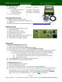
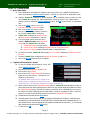
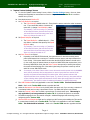
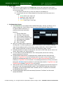
TRACKER™ TR-1 Manual v1.3
by Output Technology, Inc.
www.TrackMyOps.com
EMAIL: [email protected]
TEL:
(763) 546-9078
User’s Manual v1.3
Table of Contents
Page
COMPONENTS RECEIVED .........................................................................................................................................2
COMPONENTS NOT INCLUDED................................................................................................................................2
CONNECTION PANEL.................................................................................................................................................2
INSTALLATION............................................................................................................................................................2
TRACKER™ OPERATIONS .......................................................................................................................................3
1.
Quick Start Guide .....................................................................................................................................3
2.
“Update Job Information” Screen .....................................................................................................3
3.
“Update Tracker Settings” Screen .....................................................................................................4
4.
Start Job, End Job, and Clear Counts.....................................................................................................5
5.
Percentage Fields.....................................................................................................................................5
6.
Andon Lights ...............................................................................................................................................6
7.
Job Status Mode Screen.........................................................................................................................6
TROUBLE SHOOTING...............................................................................................................................................7
TECHNICAL INFORMATION ....................................................................................................................................7
Manual Color Key:
Display Field
Button
Page 1
© Output Technology, Inc.—All rights reserved—Specifications subject to change—Nov14. TRACKER™ Real-Time, Real Results
TRACKER™ TR-1 Manual v1.3
by Output Technology, Inc.
www.TrackMyOps.com
EMAIL: [email protected]
TEL:
(763) 546-9078
COMPONENTS RECEIVED
1. TRACKER™ TR-1:
2. Sensor Assembly:
a. Diffuse Reflective Sensor:
b. Sensor Cable:
c. Mounting Assembly:
3. Current version manual.
Part Number – (OT-60002)
Part Number – (OT-6000208)
Part Number – (OT-6000209)
Part Number – (OT-6000213)
COMPONENTS NOT INCLUDED
1.
2.
3.
4.
HDMI TV Screen (720p or compatible)
Keyboard and Mouse (USB Cable or Wireless USB)
HDMI Cable
Manual and Technical Documents available online at TrackMyOps.com/documents.html
CONNECTION PANEL
1.
2.
3.
4.
5.
6.
7.
8.
115/230 Volt, 50/60Hz, 2 Amp Power Cord
Power ON/OFF Switch
Fuse Holder (Fuse Size 500ma FA)
M12 Sensor Plug (4 wire, 24V, NPN)
Female Ethernet Port (Wired)
Female HDMI Standard Port (720p or compatible)
Female USB 2.0 Port (Wired or Wireless)
Female USB 2.0 Port (Wired or Wireless)
INSTALLATION
Steps Prior to Powering Up Your Tracker TR-1
1. Plug in user provided keyboard and mouse.
2. Plug in user provided HDMI Cable to Tracker TR-1’s HDMI port.
3. Plug in HDMI Cable to 720p TV HDMI port. Note which HDMI input number.
4. Mount included sensor to (manual or automated) production line in a position best suited to track the process.
a. Provided sensor has an approximate 2-inch range. See sensor specs for optional sensors.
b. Note: Ensure when powered up the sensor light is flashing yellow for each product as it passes.
i.
If sensor light is steady on then it is reflecting on a background object.
ii.
If sensor light does not turn yellow at all it is not “seeing” or reflecting off any object.
iii.
Reposition as necessary.
5. Plug in Tracker TR-1power cord to standard 115V/230V wall outlet.
6. Turn ON TV and set to correct HDMI input number.
Powering Up Your Tracker TR-1
7. Switch the Tracker TR-1power switch ON.
8. Power up will last about 15 seconds.
9. Verify sensor is working properly and is in correct position (per instruction 4b above).
10. The Detected Count field will increment at all times when the Tracker TR-1 is powered up and the Sensor is
detecting objects. The Detected Speed field will display line speed at all times when the Tracker TR-1 is
powered up and the sensor is detecting objects. This is true when system is in START JOB or END JOB
mode. The Detected Count field will reset to zero (“0”) when the Clear button is clicked.
Page 2
© Output Technology, Inc.—All rights reserved—Specifications subject to change—Nov14. TRACKER™ Real-Time, Real Results
TRACKER™ TR-1 Manual v1.3
by Output Technology, Inc.
www.TrackMyOps.com
EMAIL: [email protected]
TEL:
(763) 546-9078
Tracker TR-1 OPERATIONS
1. Quick Start Guide
a. Enter identification information for Operators and current Job in the “Update Job Information”
screen by clicking the Update Job Info button. Click OK or press ‘Enter’ on keyboard to save.
b. Configure Tracker TR-1 settings for specific machines (e.g. ID, multiplier, timeout counter, etc.) and
other Tracker TR-1 settings (e.g. HUB communication, sensor type, etc.) in the “Update Tracker
Settings” screen by clicking the Tracker Settings button. Click OK or press “Enter” on keyboard to
save.
c. Click on the Clear button to zero (“0”)
Detected Count and Target Count fields.
d. Click on the Start Job button to start.
e. Start your (manual or automated) production
line that the Tracker TR-1is monitoring.
f. Tracker TR-1 will display the Detected Counts
and Detected Speed (counts/hour) in real-time.
g. If an hourly target goal for counts per hour is
entered in Update Job Info in the Target/Takt
Speed field, then Tracker TR-1 will display:
i. Target/Takt Counts as a pace counter,
ii. Counts: % On Target comparing Detected Counts to Target/Takt Counts,
iii. Speed % On Target comparing Detected Speed to Target/Takt Speed.
h. If a Job Size is entered, Tracker TR-1will display Job: % Complete comparing Detected Counts to
i.
j.
Job Size.
If entered, Tracker TR-1 will display the Machine ID, Operator ID, and Job ID.
Click on the End Job button when job is complete.
2. “Update Job Information” Screen
b. To view the “Update Job Information” screen, click
on the Update Job Info button.
c. Enter alpha-numeric Operator ID and Job ID.
d. Enter numeric-only Job Size.
e. Enter numeric only Target/Takt Speed as an hourly
target rate (in counts per hour). This field will only
display as a rate per hour.
For example: enter 100 per hour for a target of 100
hourly counts; for a target of 100 per half hour, you
would enter 200; or for a target of 100 per two hours you would enter 50.
f. When a value is entered in the Target/Takt Speed field, the Tracker TR-1 will calculate the number of
pieces that should have been produced from the start of the job, and will display and update this value in
the Target/Takt Counts field. This field will continue to increment at the calculated rate for as long as
the system is in START JOB mode and in a JOB STATUS that does not disable the TAKT. Reference
page 6 for the different JOB STATUS and how they affect the Target/Takt Counts field
g. To delete all text from fields, click the Clear button.
h. A barcode scanner can be used for data entry by plugging a USB Scanner into a USB port. Each field can be
represented by its own barcode where you will need to click in each field and scan the applicable barcode. To
enter all fields at once, click in the Operator ID field, separate the fields with an underscore (“_”) in the barcode
data, scan the barcode, and click the Split button.
i.
To Save click on OK.
Page 3
© Output Technology, Inc.—All rights reserved—Specifications subject to change—Nov14. TRACKER™ Real-Time, Real Results
TRACKER™ TR-1 Manual v1.3
by Output Technology, Inc.
www.TrackMyOps.com
EMAIL: [email protected]
TEL:
(763) 546-9078
3. “Update Tracker Settings” Screen
a. To view the “Update Tracker Settings” screen, click the Tracker Settings button. Once set, these
settings should typically be constant and not need to change unless the Tracker TR-1 is moved to
another line or process.
b. Enter alpha-numeric Machine ID.
c. Set Count Multiplier as required.
i. The Count Multiplier default value is 1. Every time the sensor counts the value increments
one. If you would like value to increment by
more than 1, change Count Multiplier value.
For example, if you are running a 12 pack box
of cans and the sensor just sees the box, but
you would like to know how many cans have
been run, change the value to 12.
d. Set Speed Multiplier as required.
i. The Speed Multiplier: default value is 1. Enter
any value to increment the speed by the Speed
Multiplier value.
For example, if you are running a 12 pack box
of cans and the sensor just sees the box, but
you would like to know how many cans have
been run, change the value to 12.
e. Set Pulse Timeout as required.
i.
Depending on the JOB STATUS selected, the system knows if it should be receiving sensor
pulse inputs because line is running or if it should receive no sensor pulse inputs because line
is not running. If the system detects counts when the JOB STATUS declares it should not be
(or vice versa, when the system detects no counts in a JOB STATUS that requires them) it is in
the wrong JOB STATUS mode, after the Pulse Timeout time period (in seconds) has expired,
the system will start flashing all 4 of the Andon lights letting the operator know they need to
select the correct JOB STATUS mode.
ii.
For example, if the Pulse Timeout value is set to 60 seconds and the system is in the RUNNING
mode, but the production line has stopped and no sensor input pulses are received for 60
seconds, the system will start flashing all 4 Andon lights. When operator selects a JOB
STATUS mode that is not expecting sensor inputs, (e.g. Down for Service), the system will turn
off the 4 flashing Andon lights and activate the correct Andon light configuration for that JOB
STATUS mode. See Section 8 below for additional information on JOB STATUS modes.
f. The HUB IP Address field is only applicable to users with Tracker HUBs. This field should be left
blank. *Refer to the Tracker HUB manual to populate this field.
g. Select the Mechanical Limit Switch box by clicking within the square only if you are using a variation of
a mechanical switch and not using a photoelectric sensor. By default this option is not selected.
h. Select the Channel 2 Active box to enable a second sensor for a dual sensor input. This setting is
only applicable if you have purchased a Tracker TR-2. By default this option is not selected.
i. The default Language for the TR controller is English. Additional languages and terminology can be
configured with the Tracker HUB.
j. Wireless SSID and Passphrase fields are for configuring a Wi-Fi access point enabling the TR controller
to communicate wirelessly with a Tracker HUB. This field is only applicable to users with Tracker
HUBs. This field should be left blank. *Refer to the Tracker HUB manual to populate this field.
Page 4
© Output Technology, Inc.—All rights reserved—Specifications subject to change—Nov14. TRACKER™ Real-Time, Real Results
TRACKER™ TR-1 Manual v1.3
by Output Technology, Inc.
www.TrackMyOps.com
EMAIL: [email protected]
TEL:
(763) 546-9078
4. Start Job, End Job, and Clear Counts
a. On power up the Tracker TR-1 is in END JOB mode. The END JOB mode is identified by the red
background behind the Detected Speed and Detected Counts fields.
b. To enter the START JOB mode, click on the Start Job button. The START JOB mode is identified by
no color highlighting the Detected Speed and Detected Counts fields. When the Start Job button is
clicked, the red background behind the Detected Speed and Detected Counts fields will turn off, and
the Target/Takt Counts will begin incrementing. The JOB STATUS will flash the current start job
state of RUNNING.
c. To exit the START JOB mode and enter the END JOB mode, click on the End Job button.
d. You will use the various JOB STATUS options to record different running conditions while stopping
and starting your production line. Please reference page 6 for the definitions of available job
statuses.
e. Upon completion of the job, click End Job to move back to the END JOB mode. All counts and
speed fields will show a red background. END JOB mode designates the end of a job. Utilize the
JOB STATUS options to record downtime when a production line has stopped before the job is
completed.
f. Clicking the Clear Counts button will reset all counts back to zero.
5. Percentage Fields
a. Counts: % On Target field: This displays the ratio between Detected Counts and Target/Takt Counts as
a percentage (%). Formula is Detected Counts / Target/Takt Counts.
i. For 0 to 79% background is Red.
ii. For 80 to 94% background is Yellow.
iii. For 95 % and greater background is Green.
iv. Please note: if you place system in END JOB mode and click on Clear Counts button to set
Target/Takt Counts to zero, the Counts: % On Target field will remain at (“0”) zero.
b. Speed: % On Target field: This displays the ratio between Detected Counts and Target/Takt Speed as a
percentage. Formula is Detected Speed/Target/Takt Speed.
i. For 0 to 79% background is Red.
ii. For 80 to 94% background is Yellow.
iii. For 95 % and greater background is Green.
iv. Please note: If the production line is stopped and the sensor does not detect an object for about 15
seconds the Speed: % On Target field will turn to zero.
c. Job % Complete field: This displays the ratio between Detected Counts and Job Size as a percentage. Formula
is Detected Counts/Job Size.
i. For 0 to 99% background is Green.
ii. For 100% and greater background is Red.
iii. Please note: if no Job Size is entered the Job: % Complete field remains at zero.
d. Please note: All percentage fields will continue to calculate and display if system is in
both the START JOB and the END JOB modes, unless otherwise noted above.
Page 5
© Output Technology, Inc.—All rights reserved—Specifications subject to change—Nov14. TRACKER™ Real-Time, Real Results
TRACKER™ TR-1 Manual v1.3
by Output Technology, Inc.
www.TrackMyOps.com
EMAIL: [email protected]
TEL:
(763) 546-9078
6. Andon Lights
a. There are four (4) Andon Lights on the Tracker TR-1 screen, one in each corner of the screen.
Please refer to readily available on-line Lean Manufacturing and 5S information for best practices and
use of the Andon Lights.
i. Each Andon Light has three (3) states: Off, Steady On, and Blinking On.
ii. In the Off state, the color is faintly displayed so the operator knows where each color is
located.
1. Green Andon Light: Upper Left
2. Red Andon Light: Upper Right
3. Blue Andon Light: Lower Left
4. Yellow Andon Light: Lower Right
7. Job Status Mode Screen
a. The Tracker TR-1 is pre-configured with 9 JOB STATUS modes: Running, Job Set-up, Low on
Product, Product Out, Call for Service, Down for Service, Shift Changeover, Break, Pause.
b.
c.
d.
e.
f.
g.
For each Job Status mode there is a
predefined Andon Light combination
turned-on:
i. Running: Solid Green
ii. Job Set-up: Flashing Green
iii. Low on Product: Solid Yellow
iv. Down for Service: Flashing Yellow
v. Shift Changeover: Solid Blue
vi. Break: Flashing Blue
vii. Pause: No Lights
When job is started, system is placed into
Running mode. If product is getting low, operator should click on Low on Product. If operator
needs service assistance and line is still running, operator should click on Call for Service. If line
stops, operator should click on Down for Service, Shift Changeover, Break, or Pause.
If company would like to capture Job Set-up time, then click on START JOB, and then click on Job
Set-up. When ready to run, click on Running.
If in the middle of a job and JOB STATUS is not in Running mode, and the line is running,
operator should click on Running.
The JOB STATUS modes that are not highlighted white, indicate that when these modes are
selected, the Target/Takt Count will not increment while in this mode. If one of these modes is
selected the red background behind the Target/Takt Count and Target/Takt Speed will turn on,
indicating no Target/Takt Count will increment. The red background will turn off if any of the white
background Job Status modes are selected. No red background behind the Target/Takt Count and
Target/Takt Speed indicates Target/Takt Count will increment.
When operator clicks on START JOB, then the system starts collecting count and time values from
start of job to end of job when END JOB is clicked. Each JOB STATUS mode has a timer field in
the data file, so when the JOB STATUS mode is selected, the timer is increment for the duration
the JOB STATUS mode is active.
The JOB STATUS button display will intermittently flip between “Job Status” and the current
selected JOB STATUS.
Page 6
© Output Technology, Inc.—All rights reserved—Specifications subject to change—Nov14. TRACKER™ Real-Time, Real Results
TRACKER™ TR-1 Manual v1.3
by Output Technology, Inc.
www.TrackMyOps.com
EMAIL: [email protected]
TEL:
(763) 546-9078
TROUBLE SHOOTING
Please note: all Tracker TR-1 Systems are fully inspected prior to shipment and will ship in good working
condition.
1. Ensure TV is a 720p or compatible screen. The Tracker TR-1 will work with higher resolution TVs, including
1080 systems, that can display 720p.
2. Ensure HDMI cable is working and correctly connected to the Tracker TR-1 system and to the TV.
3. DO NOT USE any HDMI converters.
4. Ensure TV is turned on and set to the HDMI input that the HDMI cable from the Tracker TR-1 system is
plugged into.
5. If Tracker TR-1 screen does not display, ensure steps 1, 2, and 3 above are correct. Turn Tracker TR-1
system off for 20 seconds, and then turn on again.
6. If mouse or keyboard do not work: verify they are plugged in or wireless USB fob is plugged in. Turn Tracker
TR-1 off for 20 seconds, then turn on again. Tracker TR-1 system cannot be ON when plugging in the USB
or HDMI devices. The Tracker TR-1 system needs to “discover” these devices when turning on or booting
up.
7. If Sensor does not light up when hand placed in front, ensure the sensor cable is properly connected and
screwed into sensor connector on back of the Tracker TR-1. Ensure sensor cable is properly connected and
screwed into the sensor.
TECHNICAL INFORMATION
1.
2.
3.
4.
5.
Power Requirements: 115V, 50/60Hz, 500ma FA
HDMI Connection: 720p or equivalent, Type A, Full Size Female Connector
USB Connection: 2.0, wired and wireless, Type A Female Connector
Sensor: Diffuse Reflective, NPN, 12 to 24 VDC, (24 Volt Provided By Tracker TR-1, 50mm (2”) range.
Sensor Connection: M12 Connector. Pin 1: Power, Pin 3: Ground/Common, Pin 4: Signal. Any style compatible
sensor or relay input can replace provided sensor.
6. If utilizing a relay input, please note we provide the 24VDC power that needs to go through the dry contact
side of user provided relay. Does not matter if user provided relay contacts are Normally Open or Normally
Closed. Tracker TR-1 will detect state change.
Page 7
© Output Technology, Inc.—All rights reserved—Specifications subject to change—Nov14. TRACKER™ Real-Time, Real Results