1
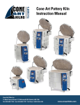
Cone Art Glass Kiln
Instruction Manual
Cone Art Kilns Inc.,
15 West Pearce Street, #7, Richmond Hill, Ontario L4B 1H6
Tel: 905.889.7705 Fax: 905.889.7707 Toll Free: 1.800.304.6185
www.coneartkilns.com
Table of Contents
Introduction. …………………………………………...………………………………… 2
Kiln Set-Up…………………………………………….………………..………………… 3
Checking the Kiln for Damage upon Delivery ………………………………3
Selecting the Best Kiln Location …………………………….………………3
Unpacking the Kiln ………………………………………………………… 3
Electrical Requirements……………………………………………………… 4
Prepare Kiln for Test Firing ………………………………………………… 4
IMPORTANT SAFETY PRECAUTIONS …………………………………………… 5
Test Firings…………………………………………………………………………….. 5
Automatic Kilns…………………………………………………………….. 6
Manual Kilns………………………………………………………………... 6
Types of Controller……………………………………………………………………… 6
Preventive Kiln Maintenance…………………………………………………………..6
Troubleshooting………………………………………………………...…..….……7
Appendix A: Kiln Disassembly. ……………………………………………………… 8
Appendix B: Element Replacement …………………………………………………… 9
Appendix C: Thermocouple Replacement…………………………………………….. 9
Appendix D: Switch and Relay Replacement ………………………………………… 10
Warranty ……………………………………………………………………………… 11
Maintenance Notes …………………………………………………………………… 12
1
CONGRATULATIONS
on your recent selection of a
state-of-the–art Cone Art Kiln
Offering excellence in unparalleled design and craftsmanship, Cone Art kilns are built with the
highest quality materials and attention to detail, resulting in the best line of electric kilns on the
market.
Please read all provided instruction manuals carefully and thoroughly before initial set-up and
operation; the information contained herein will aid you in operating your Cone Art kiln safely and
with excellent results. Instruction manuals have been provided for all optional kiln
instrumentation.
If you have any questions regarding the operation of your kiln, contact us directly at Cone Art
Kilns Inc. 1-800-304-6185 or contact your dealer.
We trust you will enjoy many years of professional results from your Cone Art kiln.
2
Kiln Set-Up
Check Kiln for Damage Upon Delivery
Every Cone Art kiln is inspected at the warehouse prior to shipment and carefully packed to prevent damage in
transit. We do recommend, however, checking for damage that may have occurred in transit. When unpacking the
kiln, if damage is discovered, follow these steps:
1. Save all packaging.
2. Call your freight carrier and ask for an inspection.
3. Notify the dealer who sold you the kiln that you have found damage and have called the freight carrier for
an inspection
4. DO NOT disassemble or fire the kiln until the damage claim is inspected and resolved.
Selecting the Best Kiln Location
It is essential to select a safe, clean and convenient location for your kiln in order to ensure long kiln life and avoid
a potential fire. Regulations about kiln placement vary; we strongly recommend consulting your local
government’s ordinances/codes to ensure safe and proper kiln location. The following are general safety and
convenience guidelines to consider:
1. Ensure that the kiln is placed in a well-ventilated area.
CAUTION: DO NOT PLACE KILN IN A CLOSET OR CABINET; it can overheat and potentially start a fire.
Any room such as a garage, shed, carport, basement, utility, or hobby room is safe if it has SUFFICIENT
CIRCULATING AIR; even so, we highly recommend installing a vent system to safely exhaust potentially
harmful fumes.
2. Set the kiln on a level and stable surface; if the floor is not concrete, it is essential that the kiln be placed on
a non-flammable surface such as firebrick or cement block.
3. DO NOT EXPOSE YOUR KILN TO THE WEATHER CONDITIONS; safe kiln operation requires your
kiln to stay dry and clean in a sheltered, yet well ventilated location.
4. Locate kiln as close as possible to an existing (or anticipated) electrical outlet.
5. Place your kiln at least 18" away from any flammable materials, including walls, drapery, paper, plastic,
cloth, etc.
Unpack the Kiln
NOTE: If you must disassemble the kiln to fit through a narrow doorway, follow the kiln disassembly instructions
contained in this manual (refer to Appendix A).
1. Carefully cut and remove the metal strapping that attaches the stand to the top of the kiln.
2. Lift kiln stand out of the box and set in the location designated for the kiln (refer to “Selecting the Best Kiln
Location” section of this manual).
3. Confirm that the stand is level and does not teeter, as an uneven stand is a safety hazard and may put stress
on the kiln during firing; if stand is not level, place firm shims under the kiln stand legs until stand is level.
4. With a partner, lift the kiln (using the exterior kiln handles when present) and place it securely and evenly
on the kiln stand. Larger kilns may best be moved in sections.
3
Ensure that Kiln’s Electrical requirements match building’s Electrical Service
1. It is essential that your kiln’s electrical requirements are compatible to your building’s electrical service;
factors to consider include voltage, amperage and phase. For example, if the kiln will be placed in a
building that is wired for 240V, you will want a kiln that is wired for 240V. If the kiln will be placed in a
building that has 208V you will want to purchase a kiln wired for 208V.
CAUTION: If you are in doubt about the compatibility of the kiln you purchased and your building’s
electrical service, we strongly recommend consulting an electrician, as an incompatible instalment will not
allow the kiln to operate properly.
2. With the exception of our 120V models the Canadian Standards Association (C.S.A.) does not allow us to
attach a plug to the kiln’s electrical cord. Because there are a variety of configurations of electrical plugs
and corresponding receptacles, it is best to have a electrician determine the connection that best suits the
requirements of the kiln and your building’s power supply. Additionally, we encourage your electrician to
directly wire the kiln into the breaker box (rather than plugging it into an outlet) as this option allows for
the safest and most efficient kiln operation.
3. We advise hiring a qualified electrician to install your kiln, as potentially dangerous voltage is involved.
The information the electrician will require, such as volts, amps, watts and phase in noted on the nameplate
of the kiln.
4. If the kiln you recently purchased is replacing an old kiln, confirm that the existing wire size is correct for
the new kiln.
Prepare Kiln for Test Firing
1. Confirm that the kiln is disconnected from the power supply (by either unplugging from receptacle or
disconnecting at breaker box).
2. Position the power cord so that it does not touch the side of the kiln.
3. Check that the lid brace is connected securely to the kiln and kiln lid.
4. If your kiln has multiple sections, inspect the latches (that lock sections together) to confirm that they have
been securely fastened.
5. Carefully vacuum any bits of brick, dust or debris that may have lodged in the kiln’s elements during
shipping.
6. Confirm that all heating elements are set into their grooves.
7. Kiln Wash or shelf primer is a coating, which it used on all surfaces that glass may come into contact with
such as shelves or molds. It is normally supplied dry and must be mixed with water. Consult your supplier
for detailed instructions regarding application of kiln wash.
8. Fumes are a natural part of any kiln firing; therefore, for your health and safety we strongly recommend
that you install a kiln vent to exhaust fumes, even in a well-ventilated area.
9. Connect kiln to power supply.
10. Read all safety precautions in the next section before proceeding to test fire your kiln.
Important Safety Precautions
CAUTION: Your kiln is a device that produces extreme heat. To prevent personal injury and/or potential fire
hazards, read and follow these safety tips prior to initial kiln operation and EVERY subsequent kiln firing.
1. Read all provided instruction manuals carefully and thoroughly before initial operation of your kiln as these
manuals contain very important information. Instruction manuals have been provided for all kiln
instrumentation.
2. Before servicing your kiln always disconnect it from the power supply.
3. Do not touch exposed electrical contacts while connected to a power source.
4
4.
5.
6.
7.
Do not stand in moisture while operating kiln and/or working with electronic devices.
Never use an extension cord with your kiln.
Keep all types of flammable materials (plastic, drapes, aprons, etc.) away from the kiln.
Do not expose your kiln to the weather conditions; safe kiln operation requires your kiln to stay dry and
clean.
8. NEVER FIRE THE KILN UNATTENDED.
9. Do not attempt to exceed the temperature rating listed on the nameplate of the kiln.
10. Observe caution when firing your kiln, as the kiln surface will become very hot; keep children away from
kiln and alert others when firing.
11. Never open the kiln unless you know it is cool.
Test Firing
You are now ready to proceed with a test firing; it is imperative that you complete this properly BEFORE
proceeding to production firing. Prior to the test firing, check electrical connections and read all provided
instruction manuals carefully and thoroughly as they contain vital information on safe kiln operation.
New kiln elements give off vapours therefore the test firing is performed with an empty kiln.
NOTE: Do not be alarmed if there is excessive smoke created during test firing; this is normal, due to lubrication
burning off the elements and starches burning out of the insulation. A clicking sound is also normal while your kiln
is firing: the elements are switching “on” and “off” in order to reach the desired temperature gradually and
evenly.
Initial Test Firing
It is advisable to do a test firing with an empty kiln before firing your work. It allows an aluminium oxide layer to
build up on the elements, which protects them from any corrosive fumes released during firing.
It will also allow you to become familiar with the operation of your kiln.
For a kiln with switches turn the switches gradually until the kiln reaches 1500ºF.
For a kiln equipped with a controller, programme the kiln to go up to 1500ºF. over 3 or 4 hours.
Refer to controller manuals for instructions.
Loading The Kiln
Always use a kiln shelf when firing. This is important even if the glass is being placed on a mold.
It is much better to ruin a shelf than a kiln floor if problems arise.
Posts are used under the shelf for more even heat distribution. Three posts per shelf is the most stable
configuration. It acts like a tri-pod and the shelf will not rock. Position the glass on the shelf or mold as desired.
Firing Instructions with manual switch Control
The following is a very general outline.
For exact firing instructions for a particular type of glass please consult your supplier. After loading the glass, prop
the lid open about 1" and open the peephole.
This allows fumes to escape.
Gradually turn your switches up until the kiln reaches 1000ºF. A good starting point is 30 minutes on a low setting
(2 or 3) and then on a medium setting until 1000ºF is reached.
Close the lid and peep holes.
5
Turn the switches to high and fire until the firing is complete.
Once you are satisfied with the results turn the kiln off and prop open the lid. This is to ensure that the glass does
not change any further.
Always use protective eyewear, gloves and clothing when firing the kiln.
When the kiln cools to 1000ºF close the lid.
The temperature will rise again. This is normal.
If you think the temperature has gone up too much prop open the lid again until it cools again to 1000ºF
Fully close the lid and anneal the glass to the temperature supplied by the glass supplier.
If you are not sure go slow. An annealing rate of between 60ºF and 100ºF per hour is a good rule of thumb.
Once the kiln has cooled below the annealing range as suggested by your glass supplier turn the kiln off.
When the kiln reaches room temperature the glass can be safely removed.
Firing with an Automatic Controller
Proceed using the instructions provided above.
Program your controller with the desired firing schedule.
As the firing proceeds check the controller to make sure it is firing the kiln as you specified.
Please refer to your controller manual for exact programming instructions.
Types of Controllers
Your kiln can be supplied in one of these ways.
1. Infinite Switch
A kiln to be manually operated comes equipped with one or more infinite switches. The higher the position
the more time the switch will be on.
For example on a low sitting the switch may be on 20% off the time and off 80% of the time. On high the
switch will be on 100 % of the time.
This type of switch is often used in conjunction with a pyrometer which measures temperature.
2. Bartlett 3 button controller
This is an automatic controller, which allows for precise control of your firing.
Please read the manual for complete instructions.
3. The Bartlett V6 Controller
This is an automatic controller which has many more options which makes firing more precise and much
more convenient.
Complete information is provided with the manual.
Preventive Kiln Maintenance
Your Cone Art kiln will provide you with many years of use: To prolong the life of the kiln and ensure error-free
operation, it is necessary to perform regular maintenance on your kiln and kiln instrumentation. We suggest the
following:
1. Inspect and vacuum element grooves regularly: dust and other debris not removed will eventually damage
the elements.
2. Check the lid and remove any brick particles.
3. Shelves may need a new layer of kiln wash: Occasionally old kiln wash must be completely removed with a
scraper and wire brush and a new layer of kiln wash evenly re-applied.
4. If your kiln is equipped with a Bartlett automatic controller, check the thermocouples before every firing
and replace them if they appear thin or corroded (approximately every 30 firings). If it breaks during a
6
firing the safety system will automatically shut off the kiln, resulting in an interrupted firing and potential
ware damage.
5. Regularly check for elements that are popping out of the grooves (careful, elements are very brittle when
cold). To repair a “popped” element: heat the element until it is glowing orange; shut off the kiln and
disconnect from electrical source by either unplugging from receptacle or disconnecting at breaker box.
With a metal instrument, carefully push the element back into place and pin with staples made from
Kanthal A-1 wire or equivalent.
TIP: Fire the kiln hotter than normal once in a while if the elements pop out regularly (this problem may occur for
those firing only to low temperatures).
6. Regularly check elements for signs of aging or need of replacement; element life span varies greatly with
element size as well as temperature and atmosphere to which you are firing.
7. Due to the expansion and contraction of heating, the electrical connections inside the switch panel may
gradually loosen; we recommend checking the connections every 25 firings to confirm that they are tight.
TROUBLESHOOTING
CAUTION: The following general checkpoints assume a basic working knowledge of electricity; it is
recommended that electrical testing, work, repairs only be performed by qualified persons since potentially
dangerous voltage is involved.
The Kiln Does Not Turn On
1. Check all electrical components (power cord, fuses, circuit breaker, etc.) for loose connections, damage or
malfunctions.
2. For kilns with Bartlett V6-CFTM automatic controllers, inspect controller fuse to confirm it is functioning
(refer to controller manual).
Tripped Circuit Breaker and/or Blown Fuses
1. Confirm that power source wiring exceeds kiln requirements; wire gauge may be insufficient to carry the
amperage demands of the kiln (if in doubt, we suggest consulting your electrician as this is a potential fire
hazard situation).
2. Ensure breaker size and/or fuse rating exceeds kiln requirements; breaker/fuses may be too small, causing
an overload (a qualified electrician should install correct breaker/fuses).
3. Check if other equipment/appliances are operating on the same circuit, potentially causing an overload.
4. Inspect the power cord for loose connections or frayed wiring.
5. Inspect the control box for signs of heat damage and loose or frayed wiring and/or connections.
6. Consult an electrician if the breaker continues to trip or fuses are continually blown.
Abnormally Long Firing Time
1. Confirm that the voltage of the power source matches kiln requirements.
2. If kiln is operated on 240V service, check fuses or circuit breaker: one of the two circuit breakers may have
tripped or one of the two fuses may have blown; if so, replace fuses or reset breaker (if fuses continue to
blow or breaker continues to trip, consult an electrician).
3. One or two components may have burned out; analyze whether it is a heating element, relay, switch, wire
or connector. Check if the heating elements are damaged or separated; check the control box for burnt,
discoloured, loose or broken wires or connectors. Finally, inspect the relays and switches for damage;
replace any damaged components.
4. Elements gradually age and need replacing; element life span varies greatly with element size as well as
temperature and atmosphere to which you are firing, so check regularly (see Appendix B for element
replacement instructions).
5. Check if other equipment/appliances are operating on the same circuit, potentially causing a power drain.
One Section of Kiln is Hotter than Normal
Check switches or relays for any visible signs of heat damage that may be forcing a switch or relay to continuously
send power to the elements, causing a section to overheat.
7
One Section of Kiln is Cooler than Normal
1. One or two components may have burned out; analyze whether it is a heating element, relay, switch, wire
or connector. Check if the heating elements are damaged or separated; check the control box for burnt,
discoloured, loose or broken wire or connectors. Finally, inspect the relays and switches for damage;
replace any damaged components.
2. Elements gradually age and need replacing; element life span varies greatly with element size as well as
temperature and atmosphere to which you are firing, so check regularly (see Appendix B for element
replacement instructions).
There are Cracks in the Kiln Lid and/or Floor Bricks
1. Hairline cracks in the lid and kiln floor are common and often occur during the first few firings as a result
of the bricks expanding and contracting.
2. These cracks will not affect the firing and it is best not to try and repair them, as repair cement will usually
shrink and crack off, taking more brick with it.
CAUTION: Never fire the kiln unattended.
Appendix A: Kiln Disassembly
In some instances it may be necessary to disassemble the kiln to go through a narrow doorway. Before
disassembling disconnect kiln from power source, save all screws and hardware for reattachment.
To Disassemble the Kiln:
1. Pull out cotter pin from end of lid hinge bar. Remove washer and slide out hinge bar/rod.
2. Remove two lid arm supports by removing two outer nuts only. Use a flat head screwdriver to press down
on the head of the inner bolt while unscrewing the outer nut.
3. Lift off lid. Carefully place down to prevent breakage.
4. Unlatch all draw latches fastening kiln sections together (along edges of each section).
5. Remove screws on right side of control panel assembly.
6. Swing control box door open.
7. Using a pair of pliers gently pull off wires from switch block or terminals. Pull off element wires with
YELLOW connectors only from relays (automatic kilns).
8. Disconnect thermocouple wire at ceramic block. Note: red is negative, yellow is positive, silver is ground.
Gently pull off ground wire at left edge of ceramic thermocouple block with pliers, then pull out red and
yellow wires by loosening screws with a Phillips screw driver.
9. Loosen copper connector screws to disconnect TOP Pair only of Black element wires from element. Do not
remove copper connectors on lower pair of black element wires. Leave fastened. (Automatic kilns)
10. Cut TOP TWO white plastic cable ties used to secure red and black element wires only along inner left
edge of control panel, along hinges. (Automatic kilns)
11. Remove screws on left side of control panel assembly.
12. On sectional kilns, remove two ¼" screws located inside the gutter on the heat shield just below
thermocouple blocks. These screws secure kiln sections together and insure a good ground connection
between top, middle, and bottom kiln sections.
13. Remove two ¼" screws at the inner bottom right corner of gutter adjacent to power cable.
14. Tap on, and slide gutter to the left to separate from kiln.
15. Set gutter/control box aside with control panel door facing up.
16. Lift top section straight up and off kiln, setting aside gently.
17. Lift mid-section straight up and off kiln, setting aside gently.
18. Move kiln to new location.
8
Appendix B: Element Replacement
Kiln elements deteriorate every time the kiln is fired; the extent of element wear depends upon the temperature
to which the kiln is fired and the amount of corrosive gases released. As the average lifetime of a kiln element
varies from 50-150 firings, occasionally one element or set of elements will require replacement.
To Replace the Element:
1. Confirm that the kiln is disconnected from the power supply (by either unplugging from receptacle or
disconnecting at breaker box).
2. Remove the screws on the right side of the control box panel and set aside. Pull the control box panel open.
3. Use a 3mm Allen wrench to loosen the two copper connectors on each end of the element to be replaced
(take note of the wires to which the element will be re-connected); if the connectors are corroded, replace
with new connectors purchased from your dealer.
4. Pull the ends of the element through the brick, taking care not to damage the brick (if the element is brittle
it may break into pieces- a pair of needle-nosed pliers can aid in removal). Remove any debris from the
element’s grooves.
5. Place the new element in the grooves; push the ends through the holes in the kiln wall. If grooves are worn
or chipped, pin the element into the grooves with staples made from Kanthal A-1 wire (element wire) or
equivalent.
6. Re-connect the element to the correct switch wires with the copper connectors (confirm that they are tight);
cut off any excess element wire extending beyond the copper connector.
7. Close the control box panel: replace the panel screws.
8. Turn on the power supply and confirm that the new element works properly by visually checking for an
orange glow.
Appendix C: Thermocouple Replacement
Over time, thermocouples gradually corrode and should be replaced at the very first signs of corrosion
(approximately every 30 firings), as even partially corroded thermocouples are not able to gauge temperature
correctly and therefore may cause an over-firing.
Your kiln is equipped with TYPE K THERMOCOUPLES. Older models carry 14 gauge thermocouples. Either
type may be used with the Cone Art pyrometer. The following are steps for replacing both types.
Replacing Thermocouple(s) in a Bartlett Automatic Controller:
1. Confirm that the kiln is disconnected from the power supply (by either unplugging from receptacle or
disconnecting at breaker box).
2. Remove the screws on the right side of the control box panel and set aside; pull the control box open.
3. Unscrew two screws on the outer edges securing thermocouple block to the kiln. Gently pull out
thermocouple and block. (BE SURE KILN IS COLD BEFORE DOING THIS).
4. Unscrew the two centre screws holding down thermocouple.
5. Remove old thermocouple
6. Install new thermocouple (ensure that the red leg is placed in the NEGATIVE (-) receptacle).
7. Replace and tighten screws.
8. Thread thermocouple into kiln though brick. Re-attach thermocouple block to kiln with two outer screws.
9. Close the control box panel; replace the panel screws.
10. Turn on the power supply and confirm that the new thermocouple works properly by observing the
temperature readout, as elements become hot.
Replacing the Thermocouple in the Cone Art Pyrometer:
1. Confirm that the kiln is disconnected from the power supply (by either unplugging from receptacle or
disconnecting at breaker box).
9
2.
3.
4.
5.
6.
7.
Remove the thermocouple block from the kiln (BE SURE KILN IS COLD BEFORE DOING THIS).
Unscrew the two centre screws of the thermocouple block.
Remove old thermocouple
Install new thermocouple (ensure that the red lead is placed in the NEGATIVE (-) receptacle).
Replace the two centre screws of the thermocouple block.
Replace the thermocouple and block in the kiln. Turn on the power supply and confirm that the new
thermocouple works properly by observing the temperature readout as elements become hot.
Appendix D: Switch or Relay Replacement:
Occasionally you may need to replace a switch or relay in order for your kiln to function.
To Install a New Switch:
1. Confirm that the kiln is disconnected from the power supply (by either unplugging from receptacle or
disconnecting at breaker box.
2. Remove the knob from the switch (this may require a small straight-blade screwdriver).
3. Remove the screws on the right side of the control box panel and set aside. Pull the control box panel open.
4. Each switch has multiple wires; with masking tape, label the damaged switch’s wires and remove.
5. Unscrew the switch nut on the front of the control box panel; remove the old switch.
6. Put the new switch in place and tighten the switch nut.
7. Re-connect the wires (marked with masking tape) to the new switch.
8. Close the control box panel; replace the screws and switch knob.
9. Turn on the power and confirm that the new switch works properly by noting that the element is glowing
and emitting a “humming” sound.
To Install a New Relay:
1. Confirm that the kiln is disconnected from the power supply (by either unplugging from receptacle or
disconnecting at breaker box).
2. Remove the screws on the right side of the control box panel and set aside. Pull the control box panel open.
3. Each relay has multiple wires. Plug each wire (one at a time) onto new relay DIRECTLY as you pull off
from old relay.
4. Unscrew the two side screws holding old relay in place, replace with new relay, and tighten in to place.
5. Close the control box panel; replace the screws.
6. Turn on the power and confirm that the new relay works properly by noting that the element is glowing and
the relay is emitting a “clicking” sound.
10
LIMITED WARRANTY
What does this Warranty cover?
This warranty covers any defect or malfunctions in your new Cone Art kiln that affect the performance of you new
Cone Art kiln.
How long does the coverage last?
The coverage of this warranty lasts for two years from the date of purchase.
What does this Warranty not cover?
This warranty does not cover the pyrometer and heating elements. In addition, any problem that is caused by abuse,
misuse (such as overriding or not operating the kiln in accordance with the printed instructions provided with the
kiln), vandalism, or an act of God (such as a fire or flood) are not covered. Incidental and consequential damages
are not covered. Some states do not allow the exclusion or limitation of incidental or consequential damages, so the
above limitation or exclusion may not apply to you. Any optional kiln instrumentation you may purchase is
covered by the warranties, if any, provided by its manufacturer and not by Cone Art Kilns Inc.
What will Cone Art Kilns Inc. do?
Cone Art Kiln Inc. will repair or replace any part, at its discretion, that proves to be defective or is malfunctioning
at no charge to you.
How do I get service?
Contact Cone Art Kilns Inc at 1 800 304 6185 or your dealer to arrange the return of defective parts.
Take a moment to fill in the following concerning your kiln; this information will be required to obtain warranty
repair.
Kiln’s Owner: ____________________________________________
Country kiln is used in: ___________________________________
Purchased from: _________________________________________
Date of Purchase: ________________________________________
Model Number: _________________________________________
Serial Number: __________________________________________
Service Voltage: _________________________________________
11
Maintenance Notes:
12