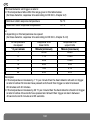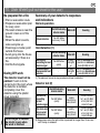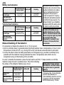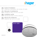
1
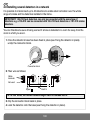
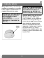
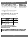
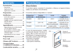
Upgraded for e-Nova applications
GB
Contents
1. introduction ................... 94
1.1 How the detector
works......................... 94
1.2 Description................ 95
2. Power supply................. 96
3. Recognition
programming ................. 96
4. installing the detector .. 97
4.1 Choosing the best
place.......................... 97
4.2 Testing the radio
range at the chosen
location ..................... 98
4.3 Fixing the detector
in place...................... 97
4.4 Installing several
detectors
in a network ............ 100
5. testing the detector.... 100
6. Manually disabling
the detector ................. 103
7. indications ................... 104
7.1 Alerts ...................... 104
7.2 Faults ...................... 104
8. Maintenance................ 105
8.1 Servicing the
detection head........ 105
8.2 Changing
the battery .............. 106
8.3 During DIY work ..... 106
1. Introduction
1.1 How the detector works
The heat detector detects rises in temperature that trigger an
alarm in the following cases:
• when the room temperature rises at an abnormal speed,
or
• when the room temperature reaches between 54°C and
70°C,
(also refer to the table in the Technical Data section).
iMPoRtAnt: the heat detector is designed to protect
homes or the private areas of buildings. it is not designed
for public assembly buildings or buildings housing workers.
The heat detector is especially suitable for detecting fires that
spread quickly or at an average speed and in places where an
optical smoke detector cannot be used:
• in a kitchen where there are cooking fumes,
• in uninhabited places where there is a smoky atmosphere or
a lot of dust (e.g. garages).
iMPoRtAnt: the heat detector is not supposed to replace
smoke or gas detectors to ensure the safety of people
against smoke or gas, and notably in rooms such as
bedrooms, playrooms and other living areas.
The heat detector can be:
• used as a stand-alone unit,
• integrated into a Daitem alarm system,
• interconnected in a hard-wired network of up to 40
detectors (heat or smoke).
9. technical data ............. 107
10. User sheet.................. 109
94
GB
In stand-alone mode, the heat detector responds as follows during the heat detection period:
When connected to a Daitem
Red LeD indicating White LeD
Sounding
alarm system the detector
detector status
responds as follows when it
a
safety
a
built-in
modulated
alarm
Heat detector
the LED flashes
detects heat:
halo
lights
sounds
on
a
continuous
transmitting the heat
quickly
up
basis (85 dB(A) at 3m)
detection signal
• triggering of the control
a safety
other hard-wired
a built-in modulated alarm
panel and security system
halo lights sounds on a discontinuous
interconnected heat
wireless sirens in fire
up
detectors
basis (85 dB(A) at 3m)
sounding mode for 5 min.,
iMPoRtAnt: the heat detector should be replaced every
• triggering of the telephone
ten years.
dialler.
1.2 Description
Red LED indicating detector status
Guarantee sticker
Product
replacement
date
Test button
White LED
(safety lighting
when heat is
detected)
Programming
key 0
Lithium
battery
connector
guarantee sticker: remove the pre-cut part of the sticker and stick it to the guarantee
certificate in the user manual supplied with the control panel. If you are adding the siren to
an existing system, use the guarantee sticker provided with this product.
95
GB
2. Power supply
Connect the lithium battery making sure it is the right way round.
Ò The red LED flashes for 15 sec, then once every 10 sec to indicate that the detector is
working normally.
3. Recognition programming
iMPoRtAnt: during recognition programming, the product to be programmed for use with
the control panel does not need to be placed next to it. in fact, we recommend you place
the product at a short distance from the control panel (at least 2 m away).
Programming enables the heat detector to be recognised by the control panel.
To programme the heat detector, the control panel must be in installation mode. If it is not,
press:
then press:
master code
engineer installer code
Carry out the programming sequence described below:
)))
))
“beep, fire detector n° X”
then
10 s max.
Press * then # on the
control panel keypad
Press & hold the programming key 0 for 10 sec.
until the control panel responds
You can record a personalised message to identify the fire detector by voice (see the
control panel installation manual, § on Voice identification message).
96
GB
4. Installing the detector
Make sure there is a distance of at least 2 m between each product, except between two
detectors.
4.1 Choosing the best place
iMPoRtAnt: the heat detector is not supposed to replace smoke or gas detectors to
ensure the safety of people against smoke or gas, and notably in rooms such as bedrooms,
playrooms and other living areas. the heat detector is designed to detect fires in places
where an optical smoke detector cannot be used. For basic protection, a smoke detector
should be installed in at least each bedroom (refer to smoke detector manual).
• far away from potential sources of electrical
interference (electricity meter, metal cabinet,
etc.),
• if it is to be installed on a metal wall, insert a
shim made of non-magnetic material (wood
or plastic).
the detector must be placed:
• in rooms where there is a risk of fires
spreading quickly or at an average speed,
• in rooms with an aggressive or difficult
environment such as kitchens (cooking
fumes), garages (smoky atmosphere), and
other unoccupied premises or rooms where
there is often a lot of dust,
• preferably at the centre of the ceiling but
positioned so that it is affected by any
abnormal rises in temperature,
• if the detector cannot be installed in the
centre of the ceiling, install it more than 50
cm away from the corners of the room (Fig.
1 and Fig. 2),
• far away from ventilation grilles that may
spread the heat,
• more than 50 cm away from obstacles
(walls, partitions, beams, etc.),
• at either end of corridors more than 8 m
long,
the detector must not be placed:
• in rooms where a sudden and considerable
rise in the room temperature would cause
untimely triggering of the alarms (e.g.
sudden sunlight),
• in rooms where there is a need to protect
people against smoke or gas(bedrooms,
children’s playrooms, converted cellars,
occupied lofts, emergency exits, etc.),
• near fluorescent tubes,
• directly on a metal surface,
• in a room where the temperature could drop
below -10°C or rise above +55°C, as this
will prevent the detector from operating
properly,
97
GB
4.2 testing the radio range
at the chosen location
• in rooms where the relative humidity might
rise above 95% (without condensation),
• close to heating, cooling or air vents.
iMPoRtAnt: the control panel must be in
installation mode to perform this test (see
Recognition programming).
Mounting examples:
Fig. 1
d > 50 cm
1. Hold down the detector programming key
0 or the test button until the built-in
sounding can be heard:
• correct: the control panel confirms the
radio link with a voice message “beep,
fire detector n° X”,
• incorrect: if there is no voice message,
move the heat detector closer to the
control panel.le.
plafond
Recommended
location
Fig. 2
2. Put the control panel back in user mode by
pressing:
d > 50 cm
engineer installer code
98
GB
4.3 Fixing the detector in place
Standard fixing method
1. Install the base in the desired location, then mark the
position of the 2 fixing holes (marked 60 or 85 ) using a
pencil.
2. Drill holes using a 5 mm Ø drill bit.
3. Fix the base using appropriate plugs and screws.
Fixing with flush-mounting box
1. For 60 mm diameter boxes: use holes marked
2. For 85 mm diameter boxes: use holes marked
3. Fix the base using suitable screws.
iMPoRtAnt: to be able
to thread the cables for
surface mounting,
remove the 2 fixing
spacers and insert them
between the ceiling and
the mounting base by
covering the 2 selected
fixing holes.
.
85 .
60
Align the 2 locating arrows
marked on the mounting
base and the detector, then
lock the unit by turning
clockwise.
v
Diameter 60 fixing holes
Test button
alignment
marker
Fixing
spacers
Diameter 85 fixing holes
optional locking of the detector on the mounting base
Optional locking is designed to prevent unauthorized
dismounting of the detector.
Using cutting pliers, cut the locking nipple.
iMPoRtAnt: opening
will now be possible
only by means of a flat
blade screwdriver.
Locking nipple
99
iMPoRtAnt: the detector
cannot be fixed to the base
if the battery is not properly
connected.
Do not use force.
GB
4.4 installing several detectors in a network
It is possible to interconnect up to 40 detectors to enable alarm activation over the whole
range of smoke and fire detectors installed in the home.
iMPoRtAnt: 155-21X heat detectors can only be connected with the same type of
detectors: e.g. a 155-21X can be connected with 155-21X heat detectors or 151-21X smoke
detectors.
You can therefore be sure of being warned if smoke is detected in a room far away from the
room in which you are in.
1. Once the detector’s base has been fixed in place (see Fixing the detector in place),
unclip the connector block.
Connector block
2. Then wire as follows:
Cable
terminals
Not used
Signal
Earth N
For 15 mm2 wires, the overall network length must not exceed 400 m.
3. Clip the connector block back in place.
4. Lock the detector onto the base (see Fixing the detector in place).
100
GB
5. Testing the detector
Although alarm sounding is reduced during a
manual test of a heat detector, it is advisable
to inform neighbours beforehand and to use
all suitable hearing protection devices.
iMPoRtAnt: so as not to cause a fire and
damage the mechanical parts and the
design of the device, never test it:
• using a naked flame,
• by moving it too close to a source of
burning heat (e.g. a paint stripper, hair
dryer, etc.).
Detection
head slot
iMPoRtAnt: you can recognise this heat
detector by the white slots in the detection
head. Unlike the smoke detector, the
smoke test spray (ref. teStFUM) is not
suitable for testing heat detector operation.
testing the detector using the test button:
When you press on the “TEST” key for
10 sec., the detector performs an automatic
functional self-test. Among other things, it
examines the state of the heat sensor located
behind the detection head slots and thus
detects any defects linked to temperature
measurement. If the heat sensor is faulty, the
heat detector indicates that there is a
technical fault (see Indications section). There
is therefore no need to test the detector using
a source of heat.
101
GB
To test the heat detector, press on the test button (for roughly 10 sec.) until the built-in
sounding is triggered. As long as the button is held down, the detector responds as follows:
Red LeD indicating
detector status
White LeD
Sounding
Heat detector
transmitting
the heat
detection signal
the LED flashes
quickly
a safety
halo lights up
every second
other hard-wired
interconnected
heat detectors
the LED flashes
quickly
a safety
halo lights up
every second
the alarm sounds
for 1 sec (75 dB(A)
at 3 m) and then
stops for 1 sec
the alarm sounds
for 1 sec (75 dB(A)
at 3 m) and then
stops for 2 sec
iMPoRtAnt: these tests should be carried out at least
once a month and notably when you have been away for a
long time.
As soon as the test button is pressed for more than 10 sec, and when connected to a
Daitem alarm system, the detector causes the following:
• triggering of the control panel and security system sirens in fire sounding mode for 5 minutes,
• triggering of the telephone dialler.
Stop the sirens and check that the control panel has memorised the alarm (see Indications
section).
102
GB
6. Manually disabling the detector
It is possible to disable the detector for a 15 min period:
• prior to activities likely to generate abnormal heat (fast rise in
temperature or increase in room temperature above 54°C,
e.g. during DIY work) and hence cause untimely triggering
of the alarm,
• to stop alarm sounding if non-dangerous heat is detected
(e.g. sudden sunshine), (only possible with the detector
having triggered the heat signal and which can be
recognised by its flashing red LED).
iMPoRtAnt: during the
15 min disable period, the
detector will not detect any
smoke or sound the alarm.
In order to disable the detector, press the test button until the
1st beep sounds or until the detector stops its built-in
sounding.
The LED indicating the status of the detector flashes every
2 sec.
Disabled heat
detector
other hard-wired
interconnected heat
detectors
Red LeD indicating
detector status
White LeD
Sounding
the LED flashes
every 2 sec.
-
-
the LED flashes
every 10 sec.
-
-
Following the 15 min disable period, the detector is
automatically reset to normal operation with the detector
status LED flashing every 10 sec.
iMPoRtAnt: to exit the disable mode before the end of the 15 min period, press the test
button until you hear the built-in sounding (see response description in the testing the
detector section).
103
GB
7. Indications...
... alerts
When your alarm system is disarmed, the control panel will report the problem with the voice
message “beep, date, time, fire alarm, detector n° X”.
... faults
iMPoRtAnt: in order not to wake you up, audible alarms resulting from power problems
or technical problems are shut down during the night. Any faults are indicated either
after daybreak for a period of more than 10 minutes or 12 hours after their occurrence.
Battery fault on the detector
Red LeD indicating White LeD
detector status
Heat detector transmitting
the fault signal
other hard-wired
interconnected heat
detectors
Sounding
the LED flashes
every 5 sec.
-
2 fast beeps
every 60 sec.
-
-
-
iMPoRtAnt: when a
battery fault occurs, the
detector continues to
function perfectly for
30 days. nevertheless,
it is advisable to replace
the battery as soon as
possible.
If the sound indication of the battery fault occurs at an inappropriate time, it is possible to
postpone its occurrence for an 8-hour delay over a maximum 7-day period by pressing the
test button until you hear the 1st beep. This is the time period available for replacing the
Lithium battery.
Battery fault on the control panel
Following a system command, the control panel issues the following voice message: “beep,
fault, battery, detector n° X”.
104
GB
technical fault
Red LeD indicating White LeD
detector status
Heat detector transmitting the LED flashes
8 times every 8 sec.
the fault signal
other hard-wired
interconnected heat
detectors
Sounding
-
8 fast beeps
every 58 sec.
-
-
If this fault appears, replace the heat detector.
Radio fault on the control panel
Following a system command, the control panel issues the following voice message: “beep,
fault, radio, detector n° X”.
8. Maintenance
8.1 Servicing the detector head
You should vacuum-clean the detection head slots if there is a lot of dust in the room.
Detection head slot
iMPoRtAnt: we advise
you to clean the detector
using a soft cloth.
never use alcohol or
acetone to clean it.
105
GB
8.3 During DiY work
8.2 Changing the battery
if the optional opening
of the detector is not
locked (see Fixing…)
if the optional opening
of the detector is locked
(see Fixing…)
1. Remove the detector from
its base by turning it
counter clockwise until
you hear a click.
1. Insert a flat blade
screwdriver into this notch.
v
v
2. Replace the worn battery.
3. Lock the detector back
onto its base (see
Fixing...).
4. Carry out a test (see
Testing the detector).
2. Remove the detector from
its base by turning it
counter clockwise until
you hear a click.
3. Replace the worn battery.
4. Lock the detector back
onto its base (see
Fixing...).
5. Carry out a test (see
Testing the detector).
the detector must not be
painted. If work is to be
carried out in the room where
the detector is installed,
completely cover the
detector using the plastic
cover.
iMPoRtAnt: do not forget
to remove the plastic cover
when the work is finished.
• the lithium battery pack must be replaced by the same type of pack with the same
technical characteristics, i.e. (3.6 V - 4 Ah).
• We advise you to use the DAiteM BatLi26 pack available in the catalogue
in order to guarantee individual safety and equipment reliability.
Li
• Dispose of the waste lithium power pack in an appropriate recycling bin.
106
GB
9. Technical data
technical data
Wireless heat detector
155-21X
Type of detection
Average coverage
Height of support
Use
Power supply
Battery life
Red indication LED
White LED
Built-in sounding
Hard-wired interconnection
Network length
Cable diameter
Radio link
Operating temperature
Storage temperature
Degree of mechanical protection
Dimensions (Ø x H)
Weight
heat detector able to detect:
• temperature rise speed
• reaching of temperatures between 54 and 70°C (see next page)
30 m2
4.5 m max
indoor
3.6 V lithium battery (BatLi 26)
approximately 5 years in normal conditions of use
• detector status
• alerts triggered
• faults
safety lighting in case of detection
• > 85 dB at 3 m in case of detection
• > 75 dB at 3 m during testing or fault indication
40 detectors maximum
400 m maximum
1.5 mm2 maximum
TwinBand® 800/400 MHz
- 10°C to + 55°C (+75°C for a short duration)
- 10°C to + 55°C / 95% relative humidity max. (without condensation)
IP 32
125 x 48 mm
210 g
107
GB
The heat detector will trigger an alarm:
• if the temperature falls within the range given in the table below:
(A2 class detector, response time according to EN 54-5, chapter 4.2)
Minimum static response temperature
54 °C
Maximum static response temperature
70 °C
or
• depending on the temperature rise speed
(A2 class detector, response time according to EN 54-5, chapter 5.4.3)
Air temperature
rise speed
° C per minute
1
3
5
10
20
30
Response time
lower limits
Minute (minimum)
29:00
7:13
4:09
2:00
1:00
0:40
Response time
upper limits
Minute (maximum)
46:00
16:00
10:00
5:30
3:13
2:25
Examples:
• if the temperature increases by 1 °C per minute then the heat detector should not trigger
an alarm before 29 minutes have passed and should then trigger an alarm between
29 minutes and 46 minutes.
• if the temperature increases by 30 °C per minute then the heat detector should not trigger
an alarm before 40 seconds have passed and should then trigger an alarm between
40 seconds and 2 minutes and 25 seconds.
108
GB
10. User sheet (pull-out sheet for the user)
Be prepared for a fire
• Plan an evacuation route.
• Prepare an evacuation plan
for every room.
• The least smoke is near the
ground: crawl out of the
house.
• When the alarm sounds,
wake everyone up.
• Prearrange a muster point
outside the house.
• Avoid going into the house
unnecessarily if there is a
fire.
• Call the fire brigade.
During DiY work
"
the detector must not be
painted. If work is to be
carried out in the room where
the detector is installed,
completely cover the
detector using the plastic
cover provided.
Do not forget to remove
the plastic cover when
the work is finished.
Summary of your detector’s responses
and indications
normal operation
Red LeD indicating White LeD
detector status
the LED flashes
once every 10 sec.
All heat detectors
Sounding
-
-
Heat detection (1)
Red LeD indicating White LeD
detector status
Heat detector
transmitting the heat
detection signal
other hard-wired
interconnected heat
detectors
the LED flashes
quickly
-
Sounding
a safety a built-in modulated alarm
halo lights sounds on a continuous
up
basis (85 dB(A) at 3m)
a built-in modulated alarm
a safety
halo lights sounds on a discontinuous
basis (85 dB(A) at 3m)
up
(1) The alarm will sound as long as abnormal heat is detected.
Detector test (2)
Red LeD indicating
detector status
White LeD
Sounding
Heat detector
transmitting
the heat
detection signal
the LED flashes
quickly
a safety
halo lights up
every second
other hard-wired
interconnected
heat detectors
the LED flashes
quickly
a safety
halo lights up
every second
the alarm sounds
for 1 sec (75 dB(A)
at 3 m) and then
stops for 1 sec
the alarm sounds
for 1 sec (75 dB(A)
at 3 m) and then
stops for 2 sec
(2) Responses when the test button is pressed for longer than 10 sec and
until the key is released.
GB
Battery fault indication
Red LeD indicating White LeD
detector status
Heat detector transmitting
the fault signal
other hard-wired
interconnected heat
detectors
Sounding
the LED flashes
every 5 sec.
-
2 fast beeps
every 60 sec.
-
-
-
technical fault indication
Red LeD indicating White LeD
detector status
Heat detector transmitting the LED flashes
8 times every 8 sec.
the fault signal
other hard-wired
interconnected heat
detectors
Sounding
-
8 fast beeps
every 58 sec.
-
-
Manual disabling of the detector
To prevent users from being
disturbed at inconvenient times,
audible indications of a battery
fault or technical fault can be
delayed for 8 hours over a
maximum period of 7 days by
holding the test button pressed
until the first beep sounds. You
should contact your installation
engineer within this same period
in order to rectify the problem.
in order not to wake you up,
audible indications of a battery
fault or a technical fault are shut
down during the night. Any faults
are reported either after
daybreak for a period of over
10 min or 12 hours after their
occurrence.
It is possible to disable the detector for a 15 min period:
• prior to activities likely to generate abnormal heat (sudden rise in temperature or rise in room
temperature of above 54°C, e.g. during DIY work), and cause unwanted alarm activation,
• to stop the alarm when the heat generated is not dangerous (e.g. sudden sunshine), (only
possible with the detector having detected the rise in temperature and which can be
recognised owing to the flashing of its red LED).
In order to disable the detector, press the test button until the 1st beep sounds or until the
detector stops its built-in audible alarm. The LED indicating
During this 15 min. period,
the status of the detector flashes every 2 sec.
Disabled heat
detector
other hard-wired
interconnected heat
detectors
Red LeD indicating
detector status
White LeD
Sounding
the LED flashes
every 2 sec.
-
-
the LED flashes
every 10 sec.
-
-
the detector will be unable to
recognise heat or generate
alarms.
Following the 15 min disable
period, the detector is
automatically reset to normal
operation and its indication
LED flashes every 10 sec.
GB
To obtain advice when installing your system or before returning equipment, please contact the Daitem
technical support team (see telephone number at the back of the alarm system installation manual).
A team of qualified technicians will tell you what to do.
ATRAL SYSTEM - F-38926 CROLLES CEDEX
www.daitem.co.uk
DeCLARAtion oF ConFoRMitY
Manufacturer: Hager Security SAS
Address: F-38926 Crolles Cedex - France
Product type: Wireless heat detector
Trade mark: Daitem
We declare under our sole responsibility that the product to which this declaration
relates is compliant with the essential requirements of the following directives:
• R&tte Directive: 99/5/eeC
• Low voltage directive: 2006/95/eC
in compliance with the following harmonised European standards:
Products code
en 300 220-2 V2.1.2
en 50130-4 (95) + A1 (98) + A2 (2002)
en 60950 (2006)
en 301 489-1 V1.8.1
155-21X
X
X
X
X
This product can be used in all EU, EEA Countries and Switzerland.
Crolles, 02.01.2013
Signature :
Patrick Bernard
Director of Research and Development
Non-binding document that may be modified without notification.
111
13
2280612004 - 01.2013