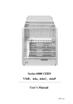
1
W-ie-
W erk für
e-R
Plein & Baus GmbH
I ndustriee lektronik
N ukleare lektronik
Regelungstechnik
Series 6000
VME, VME64x, VME64xP VXI
User’s Manual
*00501.A0
General Remarks
The only purpose of this manual is a description of the product. It must not be interpreted as
a declaration of conformity for this product including the product and software.
W-Ie-Ne-R revises this product and manual without notice. Differences of the description in
manual and product are possible.
W-Ie-Ne-R excludes completely any liability for loss of profits, loss of business, loss of use
or data, interrupt of business, or for indirect, special incidental, or consequential damages of
any kind, even if W-Ie-Ne-R has been advises of the possibility of such damages arising
from any defect or error in this manual or product.
Any use of the product which may influence health of human beings requires the express
written permission of W-Ie-Ne-R.
Products mentioned in this manual are mentioned for identification purposes only. Product
names appearing in this manual may or may not be registered trademarks or copyrights of
their respective companies.
No part of this product, including the product and the software may be reproduced,
transmitted, transcribed, stored in a retrieval system, or translated into any language in any
form by any means with the express written permission of W-Ie-Ne-R.
Mains Voltage
The Power supplies are equipped with a “World”- mains input, which works properly form
94VAC up to 264VAC and within a frequency range of 47 to 63Hz.
Before connecting to the mains please double-check correspondence.
Safety
After connecting the Power box to the mains, the mains input module is powered
permanently. Filter and storage capacitors of the power factor correction module are charged
with about 400VDC. The DC-On-Signal as well as a power switch at control board (if any
installed) operates as a DC on/off switch only and not as a mains breaker. Therefore it
becomes dangerous if the box cover is open. In this case a lot of components on high
voltage potential get touchable!
Before starting any kind of work inside the power box remove the unit from
mains and wait a couple of minutes with your activities! Discharge the primary
DC Filter-capacitors by use of a well isolated 22 ohm 10W resistor.
November 00
i
*00501.A0
Declaration of Conformity
Art. 10.2 of 89/336 and 89/392 / ECC
W-Ie-Ne-R
Plein & Baus GmbH
declare under our own responsibility that the product
VME / VXI 6021/23 Crate
Items: 0B0x.xxxx, 0F00.xxxx, 0P00.xxxx C, E
to which this declaration relates, is in conformity with the following standards or normative documents :
1.
EN 50 081 - 1
2.
EN 61 000 3 - 2
3.
EN 50 082 - 1
4.
EN 60 950
Conditions:
This crate is not a final product. The use after installation and powered modules inside needs possibly
additional screenings to be in conformity of the definition.
Admitted for powering by all mains.
Name and signature of authorized person
Place and Date
Name und Unterschrift des Befugten
Ort und Datum
Juergen Baus
Techn. Director
November 00
Febr. 2000
ii
*00501.A0
Table of contents:
1
General Information ...................................................................................................... 1
1.1 6021 Crates.................................................................................................................. 1
1.2 6020 Fan Trays ........................................................................................................... 1
1.2.1 LX Fan Trays ....................................................................................................... 1
1.2.2 EC Fan Trays........................................................................................................ 2
1.3 6021 Power Supplies................................................................................................... 2
2
Operation, Function and Connections.......................................................................... 2
2.1 Fan Tray Operation and Control............................................................................. 2
2.1.1 Function of Fan Tray Switches ............................................................................ 3
2.1.2 Additional temperature sensors ............................................................................ 4
2.1.3 Information by Fan Tray LED’s........................................................................... 4
2.1.4 Hot Swapping of Fan Tray ................................................................................... 4
2.1.5 Programming of Fan tray ..................................................................................... 5
2.1.6 Standard Measurement Ranges ............................................................................ 7
2.2 6021-6023 Bin Technical details:............................................................................... 8
2.2.1 VME-Bus Terminology, Signal Identification ..................................................... 8
2.2.2 VME (VXI) Bus Current Ratings......................................................................... 9
2.2.3 Pin Assignments of J1 and J2 VME Bus............................................................ 11
2.2.4 Pin Assignment Jaux of VME 430-Bus.............................................................. 12
2.2.5 Pin Assignments of VME 64x-Bus .................................................................... 14
2.2.6 Special Pin Assignment Jo of VME 64xP (VIPA)-Bus ..................................... 17
2.2.7 Pin Assignments of VXI-Bus ............................................................................. 18
2.3 Power Supply UEP6021 ........................................................................................... 22
2.3.1 Power Connector Board ..................................................................................... 22
2.3.2 Sense and Signal Connector-SUB D 37 ............................................................ 23
2.3.3 Fan tray and Control Connector ......................................................................... 23
2.3.4 Control and Adjustment of 6021 Power Supply................................................. 24
2.3.5 Connection of a Personal Computer to the Power Supply UEP6021................. 26
2.3.6 Output Voltage Adjustments .............................................................................. 27
3
CANbus (optional)........................................................................................................ 27
APPENDIX A : Technical Details of 6021 Power Supplies ............................................. 28
APPENDIX B : Technical Details of Fan Trays............................................................... 29
APPENDIX C : VME 430 Backplane, Situation of Jaux Connector.............................. 30
November 00
iii
*00501.A0
User’s Manual
VME 6021-23 VXI
W-Ie–Ne-R
Plein & Baus GmbH
1
General Information
1.1
6021 Crates
The VME/VXI-Crate 6021 consist of a power supply (UEP 6021), bin (UEV 6021 / 6023)
and a fan tray (UEL 6020). All these components are plugable and easily to exchange..
Divider sets 6U/9U can be mounted into bins for 9U format modules. For powering of 6021
and 6023 bins same UEP 6021 power supplies have to be used.
Standard crates are available for different module formats: 160, 220, 280, 340, as well as
400mm deep and 6 or 9 units high. 6021 bins are additionally two units and the 6023 bins
three units higher (fan tray space). Available W-Ie-Ne-R VME backplanes: VME64 with
J1/J2, VME430 with J1/Jaux/J2, VME64x, VME64xP, VME64xC with Jo special (Cern).
1.2
6020 Fan Trays
The-fan trays are plugged into the bin from the front side. For efficient cooling, controlling
and monitoring of the crate various fan trays are constructed according to the slot deepness,
whereas both, front and bottom air supply, is possible. Fan rotation speed is shown by use of
LX fan trays and can be regulated; every fan is single controlled. Furthermore temperature
of the air entry and optionally the exhaust above selected slots.
The UEL 6020 fan tray and control unit occupies two units of a 6021 crate below the VME /
VXI-bus slots.
For 6023 crates an additional plenum chamber of 1 unit homogenized the cooling air flow.
Fan trays with a depth of 160 and 220mm are equipped with three axial D.C. blowers, while
280, 340 and 400mm deep fan trays have 6 blowers. To cool the rear transition area a 9 fold
one is available.
Among the a. m. fan trays high performance super blower with four or six blowers can be
used, too. The super blower fan tray is outfitted with a topped plenum and generates a high
efficient homogenous cooling air flow through the VME modules.
The 3 fold fan-tray can operate in two different modes. Either the air is taken from the front
and then pushed upwards to the modules or from bottom side, which gives full cooling
efficiency.
The maximal air flow reached by a 3-fold W-Ie-Ne-R fan-tray with bottom inlet is greater
than 540 m3/h (LX) and shows a good homogeneity. Working with front air inlet only a
reduced air flow of about 400 m3/h is available. Due to the lower homogeneity of the air
distribution in this mode only the power dissipation of about 800 W can be cooled. The static
pressure is equal to 10 mm water column.
The EC fan tray is the economic version and equipped with same blower than the LX
version. Therefore both types give the same cooling performance
1.2.1 LX Fan Trays
All DC voltages (up to 8) at backplane level and the corresponding currents among other
are shown by the LX monitoring. The threshold-limits (minimum / maximum voltages and
currents) can be set manually or piloted by remote control and remain stored even after lack
of voltage. In case of global trip off, the fault will be displayed by the diagnostic system.
VME-signals ACFAIL and SYSRESET are generated according to VME-Specs.
SYSRESET can also be released manually.
November 00
1
*00501.A0
User’s Manual
VME 6021-23 VXI
W-Ie–Ne-R
Plein & Baus GmbH
Remote-control by network (CANbus, IEC-Bus or H.S.CAENET) is optionally possible,
whereas IEC and H.S. CAENET need the intelligent version of fan trays (LX) the CANbus
may operated with all kind of fan trays.
Furthermore, remote control and monitoring of several crates is possible through a PC's
compatible program. Change of trip off limits (specially for currents) through menu is
possible (Option). Piloting circuits are isolated from VME-potential.
1.2.2 EC Fan Trays
The simplified fan tray, UEL 6020 EC, has no further facilities than DC on / off switch and
Power LED which works also as Status indicator.
Optionally outfitted with CANbus connection.
1.3
6021 Power Supplies
The VME power supply of the 6000 series is a micro-processor controlled switching power
supply designed in the high density W-Ie-Ne-R - cavity technology, which provides a
extremely low noise output voltage.
The mains input includes a power factor correction module (PFC) with main filters, soft
start- circuit and fuses. For H and K inputs and VHC power supplies an external fuse or
circuit breaker has to be installed with a capability of 16A (H) and 32A(K). which works
according to EN 60 555-2/IEEE 555-2
The AC- input module is permanently powered after connecting the unit to the AC- mains.
POWER ON/OFF activates only the DC on/off function of the power inverter modules.
The EN 50 081-1 for generic emissions as well as the EN 50 082-1 or 2 for immunity
standards, in particular EN 55 011 RFI rejection (incl. VDE 0871 class B) and EN 55 022
electromagnetic compatibility is accomplished. The insulation performs the EN 60 950, ISO
380, VDE 0805 (SELV)! Furthermore are considered UL 1950, UL 1012, UL 478, C
22.2.950, C 22.2.220/234.
Therefore the UEP 6021 power supplies can fulfil the CE rules comprehensively and will
CE marked for use at all power nets.
Turning on the power supply all voltages reach the nominal values nearly simultaneously
within 50+/-2.5 ms (start-end-time) whereby the voltage versus time curve shows a
monotonic behavior. The start-off-time which corresponds to a value of 10% of the nominal
voltages is reached after 2.5+/-2.5 ms. The turn-on inrush current is limited by a soft startcircuit to a maximum value of 12 A.
The power packs are readily replaceable. The maximum output power is 700... 2000W with
C input and 1400... >3000W with H input, correspondence with 92... 264VAC input voltage.
For 6U power packs the output can be increased to the double if two mains input modules
work in parallel (E or K suffix).
2
Operation, Function and Connections
2.1
Fan Tray Operation and Control.
All monitoring and control operations are performed by a micro-processor based
alarm and control circuit placed inside the UEP 6021 power supply monitored by UEL
6020LX (EC via CANbus only) fan trays. To protect both the power supply and the
VME modules, a DC cut-off is started in the case of:
• overheat:
November 00
in the power modules (each module is
equipped with temperature sensors);
2
*00501.A0
User’s Manual
VME 6021-23 VXI
W-Ie–Ne-R
Plein & Baus GmbH
• overload:
if maximal current is exceeded (trip-off due to programmed
lower values is not indicated as overload)
• overvoltage:
if voltage >125% (default, crow bar function)
and if voltage >105% (default, can be changed via LX fan tray
or network)
• undervoltage:
if voltage <97.5% % (default, can be changed via LX fan tray
or network)
• fan failure:
if one or more fans fail
The reasons of a trip off will be displayed on the alphanumerical LX display.
Voltages, currents, cooling air temperatures (selectable °F - °C), fan speed, power dissipation
of inserted modules, operation time of power supply and fan tray and optional net
parameters, can be shown on the alphanumeric display of the fan-tray. The ADC resolution
is 10 bit. The accuracy of the voltage measurement is better than 0.5%. The total accuracy of
the current measurement depends on the corresponding voltage, i.e. for ±5V it is better than
2A in the range between 5A - 50A and for -2V it is better than 1A in the range between 1A 20A. Above these current ranges the accuracy is <5% of the final value. In the case of ±12V
and ±15V the accuracy is better than 0.2 in the whole current range.
2.1.1 Function of Fan Tray Switches
POWER ON /Off
main switch for ventilation and power supply
MODE SELECT
selection switch to choose items and values for fan-tray and
power supply monitoring and control
SYS RES
protected located switch for VME SYSRESET circuit activation
FAN SPEED
FAN AUTO OFF
ADDRESS
LOCAL
push button for step wise in- or decrease of fan speed.
switch to choose between local and remote warning or D.C. cutoff after fan-failure
Optional if remote network is installed
Optional if remote network is installed (IEC Bus only)
The adjusting range of fan speed is from 1200 RPM up to >3000 RPM. Pre selected
reference speed and displayed value are average RPM. The display shows the fan speed in
flashing mode if the selected speed is not equal with the true speed. This happens when
either the fans are still accelerated to the higher turns or the selected value is not reachable (if
>3000 RPM and higher density of modules inserted in the bin, etc.). After a certain time the
FAN FAIL circuit will detect this status as fan fail! While the display shows average speed
of all fans only, the CANbus option (or other supported remote interfaces) will transmit the
turns of each blower situated inside the fan tray.
November 00
3
*00501.A0
User’s Manual
VME 6021-23 VXI
W-Ie–Ne-R
Plein & Baus GmbH
2.1.2 Additional temperature sensors
Optionally installed temperature sensor(s), measuring the exhaust air, allows to switch the
fan to stop. That will be achieved by keeping pushed the FAN SPEED button to lower speed
about 10 seconds.
Also the sensor(s) will
•
accelerate the fan speed to the maximum if the first (FanUp) programmed temperature
threshold exceeds (default: 45°C) . During the out coming cooling air is above these
thresholds, adjustment to lower fan turns is disabled, until the exhaust temperature is
below the limits again.
•
switch off the power supply if the second (PsOff) programmed temperature threshold
exceeds (default: disabled) .
The sensors are placed normally above selected slots at the bin. In combination with EC fan
trays these sensors can substitute the function of the LX fan fail circuit, partially.
2.1.3 Information by Fan Tray LED’s
AC POWER
STATUS
FAN FAIL
OVERHEAT
SYS FAIL
green large LED if POWER is on
green LED if all voltages are within the limit
yellow LED if a fan failure is recognized
yellow LED if an overheat in the power supply occurs
red LED if VME-bus system generates the SYSFAIL signal
(system failure)
FAN SPEED
Red LED if fan speed below 100%
AUTO OFF
red LED indicates DC cut off disabled, remote warning only,
hot swapping of fan tray possible now
LOCAL
Optional if remote network is installed
2.1.4 Hot Swapping of LX Fan Tray
When the FAN AUTO OFF circuit is disabled (no trip off in case of any fan failure) the crate
may be fully powered during withdrawal of the fan tray. The max. DC- on time has to be
programmed (default 10s).
If programmed PsOff- limits of optional installed temperature sensors exceed during fan tray
exchange the power supply will trip off to prevent any damage to inserted modules.
November 00
4
*00501.A0
User’s Manual
VME 6021-23 VXI
W-Ie–Ne-R
Plein & Baus GmbH
2.1.5 Programming of Fan tray
Fan tray parameters (and in the same way many power supply parameters!!) may be
changed via the alphanumeric control.
The general procedure is:
- Switch the POWER and the MODE switch up simultaneous for 5 seconds. The
display shows „Config: Wait....“ and „Config: Ready !“. Then release both switches.
- If a sub-menu exists, you may now select the sub-menu item (MODE switch
up/down). If no sub-menu exists, you may change the parameter value (MODE switch
up/down)
- To change a parameter of a sub-menu, select it (POWER switch up). The selected
parameter is flashing now.
- You may alter the parameter now (MODE switch up/down)
- After finishing the parameter programming, leave the submenu or configuration
menu (POWER switch down).
Programmable parameters of a fan tray:
Mode
associated parameter
submenu
Description
Fans
Watching x Fans
Display of the number of monitored fans
Fan Temp
Temp Display: °C
Select the temperature unit: Celsius or
Fahrenheit
Temp Display: °F
Bin Temp x
Hot Swap time
The time after which the power supply will
switch off after the fan tray has been removed
(disabled, 5...30 seconds, never), must be
activated with the AUTO OFF switch)
PsOff
If the temperature of sensor x is above this
limit, the power supply will switch off.
FanUp
If the temperature of sensor x is above this
limit, the fan speed will increase to full speed.
(up to 8 sensors)
November 00
5
*00501.A0
User’s Manual
VME 6021-23 VXI
W-Ie–Ne-R
Plein & Baus GmbH
LX 6020 fan-tray front panel with optional CAENET interface
November 00
6
*00501.A0
User’s Manual
VME 6021-23 VXI
W-Ie–Ne-R
Plein & Baus GmbH
2.1.6 Standard Measurement Ranges
Available Modes and Display Examples (LX Fan trays only)
Mode
+5V
+12V
Monitored
Values
Description
5.00 V
115A.... 230A (460)
+5V channel
12.0 V
11.5 / 46.0A (92)
+12V channel
1
15.0 V
11.5 / 35.0A (70)
+15V channel
+24V )1
24.0 V
11.5 / 23,0 A (66)
+15V channel
+3,3V
3.30 V
115.... 230A (460)
3,3V channel
+48V )1
48,0 V
13,5... 67A
-5V
5.20 V
100A.... 400A
-5.2V channel
+15V )
-12V
12.0 V
6.0 / 10.0 / 40.0A (80)
-12V channel
1
15.0 V
6.0 / 10.0 / 30.0A (80)
-15V channel
-24V )1
24.0 V
6.5 / 20,0A (80)
-24V channel
-2V
2.00 V
100.0A.... 200A
-2V channel
POWER
135
W
output power
FANS
3000
RPM
fan rotation speed
FAN TEMP
25
° C or °F
fan air inlet temp.
FAN TIME
82000,6
h
Operating hours Fan tray
P.S. TIME
150000,0
h
Operating hours Power Supply
35°C
° C or °F
bin slot 1 (?) temp.
° C or °F
bin slot 2 (?) temp.
° C or °F
bin slot 8 (?) temp.
-15V )
Options
BIN TEMP 1
BIN TEMP 2
....... up to
BIN TEMP 8
Networks *
CAEN*
ADDR
99
CAENET address
BAUD*
RATE
1 MBAUD
CANbus bit rate
CANbus*
ADDR
127
CANbus address
IEC*
ADDR
25
IECbus address
)1
Either the 15V-, the 24V- or the 48V- output will be in use, depending on the
application (VME, VME64x, VXI)
November 00
7
*00501.A0
User’s Manual
VME 6021-23 VXI
W-Ie–Ne-R
Plein & Baus GmbH
2.2
6021-6023 Bin Technical details:
2.2.1 VME-Bus Terminology, Signal Identification
BR0*-BR3*
Bus request (0-3). Open-collector driven signals generated by
requesters. A low level on one of these lines indicates that some
master need to use the DTB
D00-D31
Data bus. Three-state driven bi-directional lines used to
transfer data between masters an slaves, and status/ID
information from interrupters to interrupt handlers.
DS0*, DS1*
Data strobe zero, one. Three-state driven signals used in
conjunction with LWORD* and A01 to indicate how many
byte locations are being accessed (1, 2, 3, or 4). In addition,
during a write cycle, the falling edge of the first data strobe
indicates that valid data is available on the data bus. On a read
cycle, the rising edge of the first data strobe indicates that data
has been accepted from the data bus.
DTACK*
Data transfer acknowledge. An open-collector driven signal
generated by a SLAVE. The falling edge of this signal indicates
that valid data is available on the data bus during a read cycle,
or that data has been accepted from the data bus during a write
cycle. The rising edge indicates when the slave has released the
data bus at the end of a read cycle.
GND
the dc voltage reference for the system
IACK*
interrupt acknowledge. An open-collector or three-state driven
signal used by an interrupt handler to acknowledge an interrupt
request. It is routed, by way of a backplane signal trace, to the
IACKIN* pin of slot 1, where it is monitored by the IACK
daisy-chain driver.
IACKIN*
interrupt acknowledge in. A totem-pole driven signal. The
IACKIN* and IACKOUT* signal indicates to the board
receiving it that it is allowed to respond to the interrupt
acknowledge cycle that is in progress.
IACKOUT*
Interrupt acknowledge out. A totem-pole driven signal. The
IACKIN* and IACKOUT* signal is sent by a board to indicate
to the next board in the daisy-chain that it is allowed to respond
the interrupt acknowledge cycle that is in progress.
IRQ1*-IRQ7*
Interrupt request (1-7). Open-collector driven signals, that are
driven low by interrupters to request an interrupt. When several
lines are monitored by a single handler the highest numbered
line is given the highest priority.
LWORD*
Longword. A three-state driven signal used in conjunction with
DS0*, DS1*, and A01 to select which byte location(s) within
the 4-byte group are accessed during the data transfer.
RESERVED
Reserved. A signal line reserved for future enhancements.
SERCLK
Serial clock. A totem-pole driven signal that is used to
synchronize the data transmission on the VMSbus.
November 00
8
*00501.A0
User’s Manual
W-Ie–Ne-R
VME 6021-23 VXI
Plein & Baus GmbH
SERDAT*
Serial data. An open collector driven signal that is used for
VMSbus data transmission.
SYSCLK
System clock. A totem-pole driven signal that provides a
constant 16 MHz clock signal that is independent of any other
bus timing.
SYSFAIL*
System reset. An open-collector driven signal that indicates
when a failure has occurred in the system. This signal can be
generated by any board in the system.
SYSRESET*
System reset. An open-collector driven signal, which when
low, causes the system to be reset.
WRITE*
Write. A three-state driven signal generated by the master to
indicate whether the data transfer cycle is a read or write. A
high level indicates a read operation; a low level indicates a
write operation.
+ 5 V STDBY
+ 5V dc standby. This line supplies 5 V dc to devices requiring
battery backup.
+ 5V
+ 5 V dc power. Used by system logic circuits.
+ 12 V
+ 12 V dc power. Used by system logic circuits.
- 12 V
- 12 V dc power. Used by system logic circuits.
2.2.2 VME (VXI) Bus Current Ratings
Power distribution
VME
VME
VME
VME 430
VME 64x
each slot (20°C /
70°C)
J1
J2
J1-J2
J1-Jaux-J2
J1
3,3V
17/12A
5V
9,5/7,5A
+/-12V
3,2/2,5A
9,5/7,5A
19/15A
19/15A
8,5/6A
3,2/2,5A
3,2/2,5A
1,7/1,2A
+/-15V
3,2/2,5A
-5,2V
19/15A
-2V
9,5/7,5A
Vw, Vx, Vy, Vz
V1, V2
1,7/1,2A
Layers
8
Type of ADC
mech
Termination on board
passive
J2 with 160pin
Power Connections
November 00
Studs
4
8
8
10
mech
mech
active
passive
passive
passive
active
optional
optional
optional
Studs
Studs
Studs
9
Bugs
*00501.A0
User’s Manual
W-Ie–Ne-R
VME 6021-23 VXI
Plein & Baus GmbH
Power distribution
VME 64x
VME64xP
VXI C size
VXI D size
each slot (20°C /
70°C)
J1-Jo-J2
J1-Jo-J2
Slot 2- 21)1
J1-J2
J1-J2-J3
3,3V
17/12A
17/12A
5V
15,3/10,8A
27/19A
14/10,5A
24/18A
+/-12V
1,7/1,2A
1,7/1,2A
2/1,5A
4/3A
-5,2V
10/7,5A
20/15A
-2V
4/3A
10/7,5A
+/-24V
2/1,5A
4/3A
+/-15V
Vw, Vx, Vy, Vz
4/3A
4/3A
V1, V2
1,7/1,2A
1,7/1,2A
Layers
10
18
10
10
Type of ADC
active
active
active
active
Termination on board
active
active
active
active
Power Connections
Bugs
Bugs
Studs
Studs
)1 On slot 1 of the 64xP backplane the Jo is not feeding additional 5V pins. Therefore the
current capability for +5V is only 15,3/10,8A.
November 00
10
*00501.A0
User’s Manual
W-Ie–Ne-R
VME 6021-23 VXI
Plein & Baus GmbH
2.2.3 Pin Assignments of J1 and J2 VME Bus
J1
Pin
J2
Row A
Row B
Row C
Row A
Row B
Row C
01
D00
BBSY*
D08
User defined +5 V
User defined
02
D01
BCLR
D09
User defined GND
User defined
03
D02
ACFAIL*
D10
User defined Reserved
User defined
04
D03
BG0IN*
D11
User defined A24
User defined
05
D04
BG0OUT*
D12
User defined A25
User defined
06
D05
BG1IN*
D13
User defined A26
User defined
07
D06
BG1OUT*
D14
User defined A27
User defined
08
D07
BG2IN*
D15
User defined A28
User defined
09
GND
BG2OUT*
GND
User defined A29
User defined
10
SYSCLK
BG1IN*
SYSFAIL*
User defined A30
User defined
11
GND
BG3OUT*
BERR*
User defined A31
User defined
12
DS1*
BR0*
SYSRESET*
User defined GND
User defined
13
DS0*
BR1*
LWORD*
User defined +5 V
User defined
14
WRITE*
BR2*
AM5
User defined D16
User defined
15
GND
BR3*
A23
User defined D17
User defined
16
DTACK*
AM0
A22
User defined D18
User defined
17
GND
AM1
A21
User defined D19
User defined
18
AS*
AM2
A20
User defined D20
User defined
19
GND
AM3
A19
User defined D21
User defined
20
IACK*
GND
A18
User defined D22
User defined
21
IACKIN*
SERCLK
A17
User defined D23
User defined
22
IAOUT*
SERDAT
A16
User defined GND
User defined
23
AM4
GND
A15
User defined D24
User defined
24
A07
IRQ7*
A14
User defined D25
User defined
25
A06
IRQ6*
A13
User defined D26
User defined
26
A05
IRQ5*
A12
User defined D27
User defined
27
A04
IRQ4*
A11
User defined D28
User defined
28
A03
IRQ3*
A10
User defined D29
User defined
29
A02
IRQ2*
A09
User defined D30
User defined
30
A01
IRQ1*
A08
User defined D31
User defined
31
-12 V
+5V STDBY
+ 12 V
User defined GND
User defined
32
+5 V
+5V
+5V
User defined + 5 V
User defined
No.
November 00
11
*00501.A0
User’s Manual
W-Ie–Ne-R
VME 6021-23 VXI
Plein & Baus GmbH
2.2.4 Pin Assignment Jaux of VME 430-Bus
Pin Number
Row A
Row B
Row C
01
SN1
GND
SN2
02
SN3
GND
SN4
03
SN5
GND
GND
04
CK*
GND
CK
05
SG*
GND
SG
06
CL*
GND
CL
07
-2 V
-2 V
-2 V
08
- 15 V
CE
+ 15 V
09
- 5,2 V
-5,2 V
- 5,2V
10
- 5,2 V
- 5,2 V
- 5,2V
2.2.4.1
Terminology and Signal Identification of Jaux
SN1... SN5, Binary coded slot No. lines, Geographical address
Slot Number
SN1
SN2
SN3
SN4
SN5
01
NC
GND
GND
GND
GND
02
GND
NC
GND
GND
GND
03
NC
NC
GND
GND
GND
04
GND
GND
NC
GND
GND
05
NC*
GND
NC
GND
GND
06
GND
NC
NC
GND
GND
19
NC
NC
GND
GND
NC
20
GND
GND
NC
GND
NC
21
NC
GND
NC
GND
NC
NC = No Connection (represents H- level, generated by 5k6 resistor on VME modul for
TTL, e.g.)
CK, SG and CL signals, Clean Earth
CK, Clock signal, bussed differential line terminated on both sides of the backplane (2
resistors to ground and 1 resistor in between the two lines according to the impedance .
CK
CK*
positive logic
negative logic
November 00
12
*00501.A0
User’s Manual
VME 6021-23 VXI
W-Ie–Ne-R
Plein & Baus GmbH
SG, Start / Stop Gate, bussed differential line terminated like CK lines.
SG
SG*
positive logic
negative logic
CL, Clear, bussed differential line terminated like CK lines.
CL
CL*
positive logic
negative logic
CE, Clean Earth , unbussed line without termination.
November 00
13
*00501.A0
User’s Manual
W-Ie–Ne-R
VME 6021-23 VXI
Plein & Baus GmbH
2.2.5 Pin Assignments of VME 64x-Bus
J1 (extended)
Pin No.
Row Z
Row A
Row B
Row C
Row D
01
MPR
D00
BBSY*
D08
VPC (1)
02
GND
D01
BCLR*
D09
GND (1)
03
MCLK
D02
ACFAIL*
D10
+V1
04
GND
D03
BG0IN*
D11
+V2
05
MSD
D04
BG0OUT*
D12
RsvU
06
GND
D05
BG1IN*
D13
-V1
07
MMD
D06
BG1OUT
D14
-V2
08
GND
D07
BG2IN*
D15
RsvU
09
MCTC
GND
BG2OUT*
GND
GAP*
10
GND
SYSCLK
BG1IN*
SYSFAIL*
GAO*
11
RESP*
GND
BG3OUT*
BERR*
GA1*
12
GND
DS1*
BR0*
SYSRESET*
+3.3V
13
RsvBus
DS0*
BR1*
LWORD
GA2*
14
GND
WRITE*
BR2*
AM5
+3.3V
15
RsvBus
GND
BR3*
A23
GA3*
16
GND
DTACK*
AM0
A22
+3.3V
17
RsvBus
GND
AM1
A21
GA4*
18
GND
AS*
AM2
A20
+3.3V
19
RsvBus
GND
AM3
A19
RsvBus
20
GND
IACK*
GND
A18
+3.3V
21
RsvBus
IACKIN*
SERCLK
A17
RsvBus
22
GND
IAOUT*
SERDAT
A16
3.3V
23
RsvBus
AM4
GND
A15
RsvBus
24
GND
A07
IRQ7*
A14
+3.3V
25
RsvBus
A06
IRQ6*
A13
RsvBus
26
GND
A05
IRQ5*
A12
+3.3V
27
RsvBus
A04
IRQ4*
A11
LI/I*
28
GND
A03
IRQ3*
A10
+3.3V
29
RsvBus
A02
IRQ2*
A09
LI/O*
30
GND
A01
IRQ1*
A08
+3.3V
31
RsvBus
-12 V
+5V STDBY
+12 V
GND (1)
32
GND
+5 V
+5V
+5V
VPC (1)
November 00
14
*00501.A0
User’s Manual
VME 6021-23 VXI
W-Ie–Ne-R
Plein & Baus GmbH
J2 (extended)
Pin No.
Row Z
Row A
Row B
Row C
Row D
01
User defined
User defined
+5 VAC
User defined
User
defined(1)
02
GND
User defined
GND
User defined
User
defined(1)
03
User defined
User defined
RESERVED
User defined
User defined
04
GND
User defined
A24
User defined
User defined
05
User defined
User defined
A25
User defined
User defined
06
GND
User defined
A26
User defined
User defined
07
User defined
User defined
A27
User defined
User defined
08
GND
User defined
A28
User defined
User defined
09
User defined
User defined
A29
User defined
User defined
10
GND
User defined
A30
User defined
User defined
11
User defined
User defined
A31
User defined
User defined
12
GND
User defined
GND
User defined
User defined
13
User defined
User defined
+5 V
User defined
User defined
14
GND
User defined
D16
User defined
User defined
15
User defined
User defined
D17
User defined
User defined
16
GND
User defined
D18
User defined
User defined
17
User defined
User defined
D19
User defined
User defined
18
GND
User defined
D20
User defined
User defined
19
User defined
User defined
D21
User defined
User defined
20
GND
User defined
D22
User defined
User defined
21
User defined
User defined
D23
User defined
User defined
22
GND
User defined
GND
User defined
User defined
23
User defined
User defined
D24
User defined
User defined
24
GND
User defined
D25
User defined
User defined
25
User defined
User defined
D26
User defined
User defined
26
GND
User defined
D27
User defined
User defined
27
User defined
User defined
D28
User defined
User defined
28
GND
User defined
D29
User defined
User defined
29
User defined
User defined
D30
User defined
User defined
30
GND
User defined
D31
User defined
User defined
31
User defined
User defined
GND
User defined
GND (1)
32
GND
User defined
+5 V
User defined
VPC (1)
November 00
15
*00501.A0
User’s Manual
W-Ie–Ne-R
VME 6021-23 VXI
Plein & Baus GmbH
2.2.5.1
Pin Assignment Jo of VME 64x-Bus
J0 (extended)
Pos
Row f
Row e
Row d
Row c
Row b
Row a
Row z
1
GND
User
defined
User
defined
User
defined
User
defined
User
defined
GND
2
GND
User
defined
User
defined
User
defined
User
defined
User
defined
GND
3
GND
User
defined
User
defined
User
defined
User
defined
User
defined
GND
4
GND
User
defined
User
defined
User
defined
User
defined
User
defined
GND
5
GND
User
defined
User
defined
User
defined
User
defined
User
defined
GND
6
GND
User
defined
User
defined
User
defined
User
defined
User
defined
GND
7
GND
User
defined
User
defined
User
defined
User
defined
User
defined
GND
8
GND
User
defined
User
defined
User
defined
User
defined
User
defined
GND
9
GND
User
defined
User
defined
User
defined
User
defined
User
defined
GND
10
GND
User
defined
User
defined
User
defined
User
defined
User
defined
GND
11
GND
User
defined
User
defined
User
defined
User
defined
User
defined
GND
12
GND
User
defined
User
defined
User
defined
User
defined
User
defined
GND
13
GND
User
defined
User
defined
User
defined
User
defined
User
defined
GND
14
GND
User
defined
User
defined
User
defined
User
defined
User
defined
GND
15
GND
User
defined
User
defined
User
defined
User
defined
User
defined
GND
16
GND
User
defined
User
defined
User
defined
User
defined
User
defined
GND
17
GND
User
defined
User
defined
User
defined
User
defined
User
defined
GND
18
GND
User
defined
User
defined
User
defined
User
defined
User
defined
GND
19
GND
User
defined
User
defined
User
defined
User
defined
User
defined
GND
November 00
16
*00501.A0
User’s Manual
VME 6021-23 VXI
W-Ie–Ne-R
Plein & Baus GmbH
2.2.6 Special Pin Assignment Jo of VME 64xP (VIPA)-Bus
Some user defined pins of the 64x- Jo connector have been specified in the 64xP (VIPA)
document to get available additional voltages and signals on the backplane. The slot 1 pin
out is identical to those of the Jo of the 64x pin assignment. Slot 1 to 21 are outfitted with the
following pin out:
Jo Slot 2-21
Pin Row
No. z
Row a
Row b
Row c
Row d
Row e
Row f
01
COM +5V
+5V
+5V
+5V
+5V
COM
02
COM RET_WX
Reserved
+5V
TBUS1+
TBUS1-
COM
03
COM RET_WX
Reserved
Reserved
TBUS2+
TBUS2-
COM
04
COM Vw
Reserved
USER I/O
USER I/O
USER I/O
COM
05
COM Vw
Reserved
USER I/O
USER I/O
USER I/O
COM
06
COM RET_WX
Reserved
USER I/O
USER I/O
USER I/O
COM
07
COM AREF_WX
Reserved
USER I/O
USER I/O
USER I/O
COM
08
COM RET_WX
Reserved
USER I/O
USER I/O
USER I/O
COM
09
COM Vx
Reserved
USER I/O
USER I/O
USER I/O
COM
10
COM Vx
Reserved
USER I/O
USER I/O
USER I/O
COM
11
COM Vy
Reserved
USER I/O
USER I/O
USER I/O
COM
12
COM Vy
Reserved
USER I/O
USER I/O
USER I/O
COM
13
COM RET_YZ
Reserved
USER I/O
USER I/O
USER I/O
COM
14
COM AREF_YZ
Reserved
USER I/O
USER I/O
USER I/O
COM
15
COM RET_YZ
Reserved
USER I/O
USER I/O
USER I/O
COM
16
COM Vz
Reserved
USER I/O
USER I/O
USER I/O
COM
17
COM Vz
Reserved
Reserved
TBUS3+
TBUS3-
COM
18
COM RET_YZ
Reserved
Reserved
TBUS4+
TBUS4-
COM
19
COM RET_YZ
Reserved
Reserved
TBUS_OC1
TBUS_OC2 COM
November 00
17
*00501.A0
User’s Manual
W-Ie–Ne-R
VME 6021-23 VXI
Plein & Baus GmbH
2.2.7 Pin Assignments of VXI-Bus
VXIbus J1/J2 Connector, Slot 1-13, C- and D- size
J1
J2
Pin No.
Row A
Row B
Row C
Row A
Row B
Row C
01
D00
BBSY*
D08
ECLTRG0
+5V
CLK10+
02
D01
BCLR
D09
- 2V
GND
CLK10-
03
D02
ACFAIL*
D10
ECLTRG1
RSV1
GND
04
D03
BG0IN*
D11
GND
A24
-5.2V
05
D04
BG0OUT*
D12
LBUSA00
A25
LBUSC00
06
D05
BG1IN*
D13
LBUSA01
A26
LBUSC01
07
D06
BG1OUT*
D14
-5.2V
A27
GND
08
D07
BG2IN*
D15
LBUSA02
A28
LBUSC02
09
GND
BG2OUT*
GND
LBUSA03
A29
LBUSC03
10
SYSCLK
BG1IN*
SYSFAIL*
GND
A30
GND
11
GND
BG3OUT*
BERR*
LBUSA04
A31
LBUSC04
12
DS1*
BR0*
SYSRESET*
LBUSA05
GND
LBUSC05
13
DS0*
BR1*
LWORD*
-5.2V
+ 5V
-2V
14
WRITE*
BR2*
AM5
LBUSA06
D16
LBUSC06
15
GND
BR3*
A23
LBUSA07
D17
LBUSC07
16
DTACK*
AM0
A22
GND
D18
GND
17
GND
AM1
A21
LBUSA08
D19
LBUSC08
18
AS*
AM2
A20
LBUSA09
D20
LBUSC09
19
GND
AM3
A19
-5.2V
D21
-5.2V
20
IACK*
GND
A18
LBUSA10
D22
LBUSC10
21
IACKIN*
SERCLK
A17
LBUSA11
D23
LBUSC11
22
IAOUT*
SERDAT
A16
GND
GND
GND
23
AM4
GND
A15
TTLTRG0*
D24
TTLTRG1*
24
A07
IRQ7*
A14
TTLTRG2*
D25
TTLTRG3*
25
A06
IRQ6*
A13
+5V
D26
GND
26
A05
IRQ5*
A12
TTLTRG4*
D27
TTLTRG5*
27
A04
IRQ4*
A11
TTLTRG6*
D28
TTLTRG7*
28
A03
IRQ3*
A10
GND
D29
GND
A02
IRQ2*
A09
RSV2
D30
RSV3
30
A01
IRQ1*
A08
MODID
D31
GND
31
-12 V
5V STDBY
+ 12 V
GND
GND
+24V
32
+5 V
+5V
+5V
SUMBUS
+ 5V
-24V
29
November 00
18
*00501.A0
User’s Manual
VME 6021-23 VXI
W-Ie–Ne-R
Plein & Baus GmbH
VXIbus J2 Connector, Slot 1, C- and D- size
Pin Number
Row A
Row B
Row C
01
ECLTRG0
+ 5 VDC
CLK10+
02
- 2V
GND
CLK10-
03
ECLTRG1
RSV1
GND
04
GND
A24
-5.2V
05
MODID12
A25
LBUSC00
06
MODID11
A26
LBUSC01
07
-5.2V
A27
GND
08
MODID10
A28
LBUSC02
09
MODID09
A29
LBUSC03
10
GND
A30
GND
11
MODID08
A31
LBUSC04
12
MODID07
GND
LBUSC05
13
-5.2V
+ VDC
-2V
14
MODID06
D16
LBUSC06
15
MODID05
D17
LBUSC07
16
GND
D18
GND
17
MODID04
D19
LBUSC08
18
MODID03
D20
LBUSC09
19
-5.2V
D21
-5.2V
20
MODID02
D22
LBUSC10
21
MODID01
D23
LBUSC11
22
GND
GND
GND
23
TTLTRG0*
D24
TTLTRG1*
24
TTLTRG2*
D25
TTLTRG3*
25
+5V
D26
GND
26
TTLTRG4*
D27
TTLTRG5*
27
TTLTRG6*
D28
TTLTRG7*
28
GND
D29
GND
29
RSV2
D30
RSV3
30
MODID
D31
GND
31
GND
GND
+24V
32
SUMBUS
+ 5VDC
-24V
November 00
19
*00501.A0
User’s Manual
VME 6021-23 VXI
W-Ie–Ne-R
Plein & Baus GmbH
VXIbus J3 Connector, Slot 2-13, D- size only
Pin Number
Row A
Row B
Row C
01
ECLTRG2
+24V
+12V
02
GND
-24V
-12V
03
ECLTRG3
GND
RSV4
04
-2V
RSV5
+5V
05
ECLTRG4
-5.2V
RSV6
06
GND
RSV7
GND
07
ECLTRG5
+5V
-5.2V
08
-2V
GND
GND
09
LBUSA12
+5V
LBUSC12
10
LBUSA13
LBUSC15
LBUSC13
11
LBUSA14
LBUSA15
LBUSC14
12
LBUSA16
GND
LBUSC16
13
LBUSA17
LBUSC19
LBUSC17
14
LBUSA18
LBUSA19
LBUSC18
15
LBUSA20
+5V
LBUSC20
16
LBUSA21
LBUSC23
LBUSC21
17
LBUSA22
LBUSA23
LBUSC22
18
LBUSA24
-2V
LBUSC24
19
LBUSA25
LBUSC27
LBUSC25
20
LBUSA26
LBUSA27
LBUSC26
21
LBUSA28
GND
LBUSC28
22
LBUSA29
LBUSC31
LBUSC29
23
LBUSA30
LBUSA31
LBUSC30
24
LBUSA32
+5V
LBUSC32
25
LBUSA33
LBUSC35
LBUSC33
26
LBUSA34
LBUSA35
LBUSC34
27
GND
GND
GND
28
STARX+
-5.2V
STARY+
29
STARX-
GND
STARY-
30
GND
-5.2V
-5.2V
31
CLK100+
-2V
SYNC100+
32
CLK100-
GND
SYNC100-
November 00
20
*00501.A0
User’s Manual
VME 6021-23 VXI
W-Ie–Ne-R
Plein & Baus GmbH
VXIbus J3 Connector, Slot 1, D- size only
Pin Number
Row A
Row B
Row C
01
ECLTRG2
+24V
+12V
02
GND
-24V
-12V
03
ECLTRG3
GND
RSV4
04
-2V
RSV5
+5V
05
ECLTRG4
-5.2V
RSV6
06
GND
RSV7
GND
07
ECLTRG5
+5V
-5.2V
08
-2V
GND
GND
09
STARY12+
+5V
STARX01+
10
STARY12-
STARY01-
STARX01-
11
STARX12+
StARX12-
STARY01+
12
STARY11+
GND
STARX02+
13
STARY11-
STARY02-
STARX02-
14
STARX11+
STARX11-
STARY02+
15
STARY10+
+5V
STARX03+
16
STARY10-
STARY03-
STARX03-
17
STARX10+
STARX10-
STARY03+
18
STARY09+
-2V
STARX04+
19
STARY09-
STARY04-
STARX04-
20
STARX09+
STARX09-
STARY04+
21
STARY08+
GND
STARX05+
22
STARY08-
STARY05-
STARX05-
23
STARX08+
STARX08-
STARY05+
24
STARY07+
+5V
STARX06+
25
STARY07-
STARY06-
STARX06-
26
STARX07+
STARY07-
STARY06+
27
GND
GND
GND
28
STARX+
-5.2V
STARY+
29
STARX-
GND
STARY-
30
GND
-5.2V
-5.2V
31
CLK100+
-2V
SYNC100+
32
CLK100-
GND
SYNC100-
November 00
21
*00501.A0
User’s Manual
W-Ie–Ne-R
VME 6021-23 VXI
Plein & Baus GmbH
2.3
Power Supply UEP6021
2.3.1 Power Connector Board
Ret.
17
14
U7
9
.
Ret.
11
8
Ret.
Ret.
6
Ext.
Res.
5
3
2
Ret.
U6
U5
U1
U3
U4
U0
16
13
10
7
4
1
Ret.
Ret.
Pin 10,11,13...18:
Pin 1...9+12:
Ret.
D-SUB 37
12
15
D-SUB 9
U2
18
Ret.
6mm, 120A max.
8mm, 240A max
Return from common ground rail at backplane
Voltages and Pin outs in Standard VME application
U0
5V (2... 7V) < 230A
U1
+12V (7... 24V) < 92A
U2
+15V (7... 24V) < 92A
U3
3,3V (2... 7V) < 230A
U4
-5,2V (2... 7V) < 230A
U5
-12V (7... 24V) < 92A
U6
-15V (7... 24V) < 92A
U7
-2V (2... 7V) < 115A
Voltages and Pin outs in Standard VME64x application
U0
5V (2... 7V) < 230A
U1
+12V (7... 24V) < 92A
U2
+48V (30... 60V) < 92A
U3
3,3V (2... 7V) < 230A
U5
-12V (7... 24V) < 92A
U4
U6
-15V (7... 24V) < 92A
U7
Voltages and Pin outs in Standard VXI application
U0
5V (2... 7V) < 230A
U1
U2
+24V (12... 30V) < 92A
U3
U4
-5,2V (2... 7V) < 230A
U5
-12V (7... 24V) < 92A
U6
-24V (12... 30V) < 92A
U7
-2V (2... 7V) < 115A
November 00
22
+12V (7... 24V) < 92A
*00501.A0
User’s Manual
W-Ie–Ne-R
VME 6021-23 VXI
Plein & Baus GmbH
2.3.2 Sense and Signal Connector-SUB D 37
19
TEMP RETURN
37
TEMP 0
18
TEMP 1
36
TEMP 2
17
TEMP 3
35
TEMP 4
16
TEMP 5
34
TEMP 6
15
TEMP 7
33
BIN EEPROM: IIC SDA
14
BIN EEPROM: IIC SCL
32
BIN EEPROM:+5V
13
VME LOGIC: SYSRESET
31
BIN EEPROM: GND
12
VME LOGIC: ACFAIL
30
VME LOGIC GND
11
VME LOGIC: SYSFAIL
29
U0 SENSE -
10
U0 SENSE + (VME: +5V)
28
VW SENSE (reserved)
9
VW SENSE (reserved)
27
VX SENSE (reserved)
8
VX SENSE (reserved)
26
U4 SENSE +
7
U4 SENSE -
25
U7 SENSE +
6
U7 SENSE -
24
U2 SENSE -
5
U2 SENSE + (VME: 48V)
23
U6 SENSE +
4
U6 SENSE -
22
U1 SENSE -
3
U1 SENSE + (VME: +12V)
21
U5 SENSE +
2
U5 SENSE – (VME: -12V)
20
U3 SENSE -
1
U3 SENSE + (VME: +3.3V)
5
CAN_H
2.3.3 Fan tray and Control Connector
9
CAN_L
4
CAN GND
8
RXD
3
TXD
7
+15V (for fan only)
2
+15V (for fan only)
6
-15V (for fan only)
1
-15V (for fan only)
The CANbus Logic is an option. Data exchange between fan tray and power supply
has been done by use of serial connection via RXD and TXD.
November 00
23
*00501.A0
User’s Manual
VME 6021-23 VXI
W-Ie–Ne-R
Plein & Baus GmbH
2.3.4 Control and Adjustment of 6021 Power Supply
2.3.4.1
Control of the Power Supply 6021 via CAN-Bus (optional)
The CAN Bus Signals are provided on the 9 Pin DSUB:
CAN_H:
Pin 5
CAN_L:
Pin 9
CAN_GND:
Pin 4
The software protocol is described in a separate document (Part No *00183)
CANbus is an independent port. It may used to operate the power supply separately or
in combination with the fan tray inside the bin
2.3.4.2
Control of the Power Supply 6021 without PC or Control panel
(display)
There is a on/off input and a status output function wich are used in combination with
an EC- fan tray :
Remote On:
9 Pin DSUB: Close a “make” contact or switch between Pin 8 (Serial
Data In, RXD) and Pin 2 or 7.
Status Output: 9 Pin DSUB: Connect a LED between Pin 3 (Serial Data Out, TXD)
and Pin 1 or 6.
2.3.4.3
Control of the Power Supply 6021 via Fan tray
Many power supply parameters may be changed via the alphanumeric control of the
connected fan tray.
The general procedure is:
- Switch the POWER and the MODE switch up simultaneous for 5 seconds. The
display shows „Config: Wait....“ and „Config: Ready !“. Then release both switches.
- If a sub-menu exists, you may now select the sub-menu item (MODE switch
up/down). If no sub-menu exists, you may change the parameter value (MODE switch
up/down)
- To change a parameter of a sub-menu, select it (POWER switch up). The selected
parameter is flashing now.
- You may alter the parameter now (MODE switch up/down)
- After finishing the parameter programming, leave the submenu or configuration
menu (POWER switch down).
November 00
24
*00501.A0
User’s Manual
VME 6021-23 VXI
W-Ie–Ne-R
Plein & Baus GmbH
Table 1 List of manual Programming Features
Mode
associated parameter
submenu
Any
Voltage Ilim
(e.g. +5V or U0)
Uadj
Power
Output Current limit
Output voltage fine adjustment. The same
function as the switches in the power supply
Unom
Output voltage coarse adjustment.
Imax
Monitoring: Maximum current for good
status.
Umin
Monitoring: Minimum voltage for good
status.
Umax:
Monitoring: Maximum voltage for good
status.
Auto Power On
Automatic switch on of the power supply after
come back of the mains
No Auto Power On
Switch Off Normal
Switch Off Delay
November 00
Description
Delayed switch off: You have to push the
POWER switch down for 5 seconds until the
power supply switches off
25
*00501.A0
User’s Manual
W-Ie–Ne-R
VME 6021-23 VXI
Plein & Baus GmbH
2.3.5 Connection of a Personal Computer to the Power Supply UEP6021
The needed staff is an PC running Windows, the control program UEP6 and a simple
adapter (“Dongle”). For more details, view the document *00461.A0.
X3, 9 Pin DSUB
male (UEP6)
9 Pin DSUB female
(PC)
3
2
8
3
7
1 kOhm
5
6
1 kOhm
100nF
November 00
26
*00501.A0
User’s Manual
W-Ie–Ne-R
VME 6021-23 VXI
Plein & Baus GmbH
2.3.6 Output Voltage Adjustments
All output voltages can be adjusted manually via the two rotary switches situated on the
power supply top.
Channel selection
(0:Uo...7:U7)
Adjustment
+
3
Mode Selection
Function
0-7
Adjust Voltage of U0-U7
A
CAN Address (low, Bit 0-3)
B
CAN Address (high, Bit 4-6)
C
CAN General Call Address (low, Bit 0-3)
D
CAN General Call Address (high, Bit 4-6)
E
CAN Transmission Speed Index
CANbus (optional)
CAN Transmission Speed Index
Index
Max. Distance
Bit Rate
Type
high- speed
0
10 m
1.6 Mbit/s
1
40 m
1.0 Mbit/s
2
130 m
500 kbit/s
3
270 m
250 kbit/s
4
530 m
125 kbit/s
5
620 m
100 kbit/s
6
1.300m
50 kbit/s
7
3.300 m
20 kbit/s
8
6.700 m
10 kbit/s
9
10.000 m
5 kbit/s
(needs termination)
low-speed
For software protocol see separate manual No. *00183
November 00
27
*00501.A0
User’s Manual
W-Ie–Ne-R
VME 6021-23 VXI
Plein & Baus GmbH
APPENDIX A: Technical Details of 6021 Power Supplies
Mains input
C/E Sinusoidal:
92...264VAC, 10/20A
H/K Sinusoidal:
92...264VAC, 15/30A
Inrush current:
Isolation
Inp.- outp.
CE
EN 60555, IEC 555 pow. fact. 0,98 (230VAC),
CE
EN 60555, IEC 555 pow. fact. 0,98 (230VAC),
limited to nominal input current, max.
CE
EN 60950, ISO 380, VDE 0805, UL 1950, C22.2.950
Output, power with different mains inputs, DC- voltages
C 700... 2100W, E 1400... 4000W, H 1000... 3000W, K 2100... 6000W
Available modules
min. to max. range
max. output
Type
Type
Type
Type
MEH
MEH
MEH
MEH
2...
7...
12...
30...
7,0V
16V
30V
60V
115A / 550W
46A / 550W
23A / 550W
13,5A / 650W
Type
Type
Type
MDH
MDL
MDL
2...
7...
7...
7,0V
24V
30V
(+/-)
(+/-)
(+/-)
(with C, E, H, K mains input)
20A / 140W (280W)
11,5A / 140W.(280W)
7,4A / 180W.(360W)
3U box with alternative C or H input, 6U box suitable for all inputs., above 16A AC input
terminals with 2m power cord, fixed . Available output power depends on input voltage
Regulation
static: MEH 550W/650W
MDH (20A):
MDL (11,5A/7,4A):
<25mV
<0,1%
<0,1%
dyn.:
<100mV
<0,7%
(+/-25% load)
(+/-25% load)
Recovery time +/-25% load:
Modules 550W
Modules 650W
MDL (11,5A/7,4A):
within +-1%
0,2ms
0,5ms
0,0ms
within +-0,1%
0,5ms,
1,0ms
1,0ms
Sense compens. range:
difference between min. and max. output voltage
Noise and ripple:
<10mVpp, (0-20MHz )
MEH, MDH
MDL (11,5A/7,4A):
(+/-100% load, +/- full mains range)
(+/-100% load, +/- full mains range)
(+/-100% load, +/- full mains range)
<3mVrms (0-2MHz)
EMI
RFI-rejection(emission):
EMC
(immunity):
CE
CE
EN 50081-1 VDE 0871B
EN 50082-1 or 2
Operation temperature:
0....50°C without derating,
Storage:-30°C ... +85°C
Temp.-coefficient:
Stability (conditions const.):
< 0,2% / 10K
10mV or 0,1% / 24 hours, 25mV or 0,3% / 6 month
Current limits:
adjustable to any lower level
Voltage rise characteristics:
monotonic 50ms, processor controlled.
Overvoltage crow bar protection:
DC Off (trip off):
trip off adjusted to 125% of nominal voltage each output
within 5ms if >2% deviation from adjusted nominal
values,
after overload, overheat, overvoltage, undervoltage (bad
status) and fan fail
if temperatures exceed 110°C heat sink, 70°C ambient
Trip off points adjustable, processor controlled. Output capacitors will be discharged by the
crow bars
November 00
28
*00501.A0
User’s Manual
W-Ie–Ne-R
VME 6021-23 VXI
Plein & Baus GmbH
Efficiency:
75% ... 85%, depends on used modules
M T B F:
40°C ambient >65 000 h
25°C ambient >100 000 h
APPENDIX B: Technical Details of Fan Trays
Fan Tray Type
Facilities
No. of Blowers
Depth
Max. Air Flow
6020LX/3
Intelligent
3 x DC
160 mm
>540m 3 / h
6020 EC/3
Simplified
3 x DC
160 mm
>540m 3 / h
6020LX/6
Intelligent
6 x DC
370 mm 1)
>1000m 3 / h
6020 EC/6
Simplified
6 x DC
370 mm 1)
>1000m 3 / h
6020LX/4s
Intelligent
4 x DC-Super
400 mm 2)
>1500m 3 / h
6020 EC/4s
Simplified
4 x DC-Super
400 mm 2)
>1500m 3 / h
6020 LX/6s
Intelligent
6 x DC-Super
600 mm 2)
>2200m 3 / h
6020 EC/6s
Simplified
6 x DC-Super
600 mm 2)
>2200m 3 / h
6020 LX/9
Intelligent
9 x DC
600 mm 2)
>1600m 3 / h
6020 EC/9
Simplified
6 x DC
600 mm 2)
>1600m 3 / h
1)
changed to 400mm, compatible to 4-fold Super Blower fan tray dimension
2)
all 400mm and 600mm fan trays for bottom air inlet only. Equipped with topped
plenum chamber, 25mm high.
Static pressure:
DC blower
10 mm H2O column
DC Super blower
15 mm H2O column
Operating Temperature:
0... 70°C
MTBF:
>65 000 h at 40°C ambient, > 85 000 h at 25°C ambient
November 00
29
*00501.A0
User’s Manual
VME 6021-23 VXI
W-Ie–Ne-R
Plein & Baus GmbH
APPENDIX C: VME 430 Backplane, Situation of Jaux Connector
November 00
30
*00501.A0