1
Level switches (controllers) for liquid levels
limit states and other physical quantities,
type SPC - 1K
including
DPZ-2R... two-state impedance converters (relays)
and CZP-1... electrode level sensors (probes)
User’s manual
No. 060323MCE
Edition. 25.04.2006 (acc. to 040430_09.11.2004)
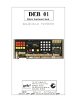
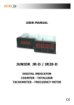
Fig. 1
SPC-1K level switches – view of selected unit types
1 Application
SPC-1K level switches are intended for use in signalling circuits and/or control of levels of media such as: water, waste water,
pulps, syrups, emulsions, chemicals, drinks, milk, coal, wet sand and soil, moulding sand, farm produces etc. Do not use for
fuels, oils, places where explosion hazard is present etc.
Intended for use in facilities such as: wells, pipelines, reactors and chemicals containers, sink basins and water discharge
basins, intermediate pumping stations and oil traps for waste water, rooms with threat of flooding, pressure expansion vessels,
boilers, autoclaves, silos etc.
The converters are intended for permanent incorporation into protective cabinets or housings while the sensors are designated
for permanent installation in the unit where the medium level or presence (or absence) is to be signalled.
Detailed circuit and environmental conditions in which the level switch can be used are based on the further information and
parameters to be followed.
The level switch and/or its assemblies are components intended for signalling and control systems. Before they are used a
relevant technical design must be prepared to associate the level switch with the object and other components indispensable for
the performance of the necessary functions. The design should be prepared by a specialist (e.g. an electrician) holding the
necessary licenses. Both the design and the execution must meet the requirements and recommendations indicated in this
manual and the requirements and recommendations of the regulations in force for the individual object. The circuit made
according to the design should guarantee the safety of people, animals, property and environment.
2 Operation
The operation of the level switch is based on the impact of the of the sensor electrode with the electricity-conducting medium
on the electric resistance (impedance) of that electrode against the container walls (or the counterelectrode).
2
3 Design
SPC-1K level switch is a selected set composed of an electrode level sensor, CZP-1 type (Fig. 3) and a two-state impedance
converter DPZ-2R type (feeder-relay) - (Fig. 2).
Sensor (Fig. 3) has a casing with taper pipe or metric thread. A special electrode is embedded in the casing, properly isolated
from the casing, with a thread clamp for connecting a conductor. The clamp is shielded with a heat-resistant flexible cap.
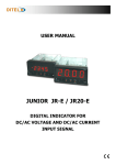
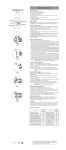
Fig. 2 Dimensions of DPZ-2R converter including PZ11 type
Relpol socket.
Fig. 3 Dimensions of CZP-1 R1/4 sensor
(basic version)
The design of the converter (Fig. 2) is of a block type with a multipin (11-pin block) intended for standard 11-contact sockets
(PZ-11 socket of Relpol-śary is required or other socket with identical arrangement of terminals and of not worse electrical
parameters).
Schematic and block diagrams of the entire level switch in two basic application circuits and the application functions of
those circuits are illustrated in figures 4 and 5. The electric circuit can be powered from 230V AC network or with 24V AC
current (terminals 4,5) or 12 or 24 V DC current (via internal converter; power supply: terminal 4: „+” , 5: „–” ). Input circuits
(terminals 9,10,11,1,2,3) are isolated from the power supply by a low-power separating transformer (Tr) (also where DC is
used). The circuit includes a transistor-based detecting amplifier (Wd) and a bistable amplifier (Wp) with hysteresis (flip-flop),
output control relay (P) and signal lamps (optical level switches) (Sz) and (Sc)
The detecting amplifier (Wd) is interfaced with the bistable amplifier (Wp) by a delay element composed of a resistor (Ro)
and a delay capacitor (Co). The switching delay can be increased using an external capacitor (Cd). The delay value without the
use of the Cd capacitor is optimal for most of the applications.
Auxiliary alternative voltage (Up) is derived from the secondary winding of the separating transformer (Tr) and supplied to a
measuring divider formed of an internal range resistor (Rzk) and an external range resistor (Rd) and the measured impedance
of the CZP-1sensor. The divider tap is connected to the input of the detecting amplifier (Wd). The control impedance that coforms the measuring divider (the impedance of the CZP-1sensor) has an impact, depending on its value, on the level of the
alternating output voltage of the detecting amplifier (Wd) and hence it correspondingly biases the flip-flop (Wd).
The control impedance values for which the relay states are changed (equal to switching resistance values) are a result of the
total value of the internal range resistor (Rzk) and the additional range resistor (Rd) (and optionally an additional reducing
resistor Rdr connected to the terminals 2-11).
The value of the internal range resistor (Rzk) (7.5 kΩ) is selected so as to allow the level switch to meet the requirements of
the most of typical applications with a zero value of the additional external range resistor (Rd).
The flip-flop switching points (expressed as switching resistance values) are selected in such a way that their average
arithmetic value (median; threshold) for both basic application circuits (Fig. 4 and 5) is approximately the same. Consequently,
the switching resistance values for a specified Rd value, for both application circuits, are the same (this simplifies the selection
of the Rd resistor).
The flip-flop (Wp) controls the output electromagnetic relay (P) including 1 pair of switching contacts constituting a voltagefree output of the entire level switch and controls the signal lamps (optical level switches).
The red lamp (Sc) goes on when the electromagnetic relay is energized while the green lamp (Sz) goes on to indicate that the
relay is de-energized (it is the other way round for DPZ-2Rzp version).
3
The possibility to swap the range resistor and the sensor impedance in the measuring divider circuit allows a free selection of
one of the above application circuits by the user. The minimum level signalling circuit (Fig. 4) enables the output relay once
the level exceeds the required minimum. The circuit is suitable to indicate the minimum level because the drop of the liquid
level in the tank below the required minimum level results in a state of output terminals identical to that when no power is
present, which causes that any possible power failure is indicated as an emergency and so is the drop of the liquid level below
the warning minimum level. The operation of the circuit shown in Fig. 5 is opposite. The consequence of such solutions is a
simplification of the level switch and high reliability.
Output
The converter is a universal block of permanent, unchanged parameters the features and parameters of which can be adjusted
over a wide range by the user via an external connection and an attachable additional range resistor (Rd) an/or reducing resistor
(Rdr) and optionally an additional delay capacitor (Cd).
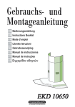
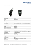
Fig. 4 Inversion-type “minimum level” signalling circuit.
a) Circuit diagram (position of output contacts Nos. 6,7,8 for power-off on terminals Nos. 4 -5).
b) State of output contacts and the optical level switch for the electrode emerged above the surface.
c) State of output contacts and the optical level switch for the immersed electrode.
Output
1. CZP-1 sensor; 2. Conductive liquid; 3. Tank; 4. Sensor housing (according to DT-UC-90/WO-A/02 item 8.2.1 ) ; 5. Connection line; 6.
DPZ-2R converter; 7. Level switch output; Sz – green lamp (optical signalling) ; Sc – red lamp (optical signalling) ; Rd – additional range
resistor to set the range (sensitivity) of the converter; Cd – additional capacitor to set the switching time (above the nominal one) ; P –
output relay.
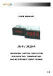
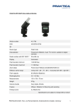
Fig. 5 Non-inversion-type “maximum level” signalling circuit – key: see Fig. 4
a) Circuit diagram (position of output contacts Nos. 6,7,8 for power-off on terminals Nos. 4 -5)
b) State of output contacts and the optical level switch for the immersed electrode.
c) State of output contacts and the optical level switch for the electrode emerged
Max
above the surface.
Fig. 6 Sample installation of CZP-1R1/4.. sensor
inside a pipe or a tank (it is recommended to follow the general principles
illustrated in the figure also for installation of other sensor types
4
4 SPC-1K level switch parameters.
DPZ-2R.. converter
Power supply Un; options 50Hz 230V 10mA; 24V 80mA
Tolerance +10%, -15% DC 12V 70mA; 24V 30mA
Breaking (switching) capacity 8A; 250 V AC; 2 kVA (cosφ=1)
Light signalling
red - ON ; green - OFF
green - ON ; red -OFF
for DPZ-2Rzp version
Ambient temperature
-25 ÷ 55 °C
Sensitivity (switching
~ 7.5 kΩ + Rd (see Tab.1)
CZP-1 .. sensor (probe)
Liquid pressure *
Liquid temperature
for CZP-1w version
„Moisturized” materials
Connector thread * (taper type)
for CZP-1-35 type
Electrode diameter
≤ 4.0 MPa
≤ 250 °C (for water saturated vapour pressure)
≤ 100 °C (possible ≤ 250 °C)
1H18N9T*, PTFE (PE for ”-w” version 100°C )
R1/4 or MK20 x 1.5; sealed with PTFE tape
M20x1.5 (straight type); flat gasket
4 mm
threshold)**
Hysteresis (rel.to the
~ + 30% *
for CZP-1w type
8 mm
switch.thresh)
Time delay (τ ; sec. ) *
for DPZ-2Rzw version
Voltage at the sensor
Insulating strength
τ=(<1) + (~ Cd. •5 • 104 )
τ ON <1 ; τ OFF = ~ 5 sec.
Very low ( ≤ 7 V~)
2.5kV~ (4kV relay and
Electrode lengths [m]
Additional electrodes
extending the sensor
Insulation strength
L = 0.15 ; 0.45 ; 0.95 + 1.0 ; 2.0 ...
EKD-1; ∅4; (in EKD-1w ∅8) L = 1 m (with
threaded ends and a thread connector)
1.0 kV (dry)
Terminal protection grade
IP 55 (IP67 if cap filled with silicone)
transformer)
Protection grade
Overvoltage category
IP 00
II
Applied voltage at the sensor ≤ 50 V AC DC
*Upon agreement the parameters can be changed to be made more stringent according to the user’s requirements. If used for caustic liquids
(e.g. acids) provide type, strength, and temperature of liquid in order to select an appropriate material of the electrode and housing.
** Converter sensitivity (switching threshold, range) = arithmetic mean of two resistance values for which the output relay is switched on
and off, resulting from the resistance value of the additional range resistor Rd and optionally the reducing resistor Rdr.
The 12V DC and 24V DC versions are equipped with electrical isolation from the power supply; for those versions the „+” of the power
supply must be connected to terminal 5, while the „ - ” must be connected to “4”.
Stub pipes with G1/4 or M 20x1.5 threaded holes can be supplied for the sensors (to be welded-in).
For CZP-1-35 sensor (which replaces the no longer used SK-35 probe) the electrode length is L= ~60mm – extended with an additional
EKD-1 electrode.
5 Recommendations for installation and safety of use
Caution: Any works can be performed after this manual and the design referred to in Item 1 have been carefully read. The principles
given in the manual and design must be followed. Non-compliance with the said principles may result in electric shock to persons and/or
damage to the equipment.
Install the converters in cabinets or boxes which meet the requirements of the safety standards so that the terminals and other components
connected to dangerous voltage are efficiently shielded preventing the occurrence of the dangerous voltage on the conductive components
accessible to people and animals (connect metal cabinets or enclosures and other conductive components to the protective conductor).
Connect the (metal) tank and/or the ground electrode to the protective conductor also.
Caution: Impedance of protective connections must be as low as possible so that in case of any short-circuit the voltage that might
occur on the accessible conductive components does not exceed the value of 10V for the short circuit current equal to double rated current
of the fuse used in the circuit protected.
Caution: Should any of the input circuits (terminals Nos. 9,10,11,1,2,3) be accessible to people and/or animals (this applying also to
sensors connected to those terminals and/or other components which conduct electricity), 12V DC or 24V DC or 24V AC converters must
be used and the circuits connected to the outputs (terminals Nos. 6, 7, 8) must be of safe voltage type (e.g. 24V). Where a higher voltage is
to be used (e.g.230 V) additional protective impedance must be installed (e.g. protective differential switch). For versions supplied with
voltage higher than safe voltage (e.g. 230V~), whole of the power must be supplied via protective differential switch. In addition to the
above conditions quick-break fuses must be used in the power supply circuits connected directly or indirectly with the converters,
corresponding to the power of the appliances connected but in any case of the rating not exceeding In=8A; such circuits must be equipped
with an easily accessible, explicitly marked and easily identifiable switch compliant to PN-EN 60947-1
Install the switches in places free from risk of mechanical impact (this applying mainly to terminals) or use appropriate guards.
It is recommended to install the sensor in the upper (see example in Fig. 6) or side wall of the tank, or on extension arms, positioned
vertically or obliquely down. Horizontal and other mounting positions are allowed for fairly clean liquids. Order sensors with extended
insulation for heavily polluted liquids.
The sensor mounting hole should have an appropriate thread type (e.g. G 1/4 for R1/4; M20x1.5 for MK20x1.5) undamaged, without
sharp edges, chips etc. Seal the pressure vessels sensor thread with thread teflon (PTFE) tape.
Cut the electrode to length before mounting the sensor. The length of the non-insulated electrode part should be ≥ 5 mm (recommended
≥ 50mm). Where an electrode ≥ 0.95m must be used extend it with additional EKD-1.. electrodes supplied to order (for lengths of approx.
2 m and more and/or strong liquid swirls the use of CZP-1w reinforced sensors is recommended. For heavy exposure purposes and dry
loose materials use heavy duty CZP-1cG.. sensor (see category card CZP-1cG..).
Gaps between the sensors and the distance from the tank walls depend on the sensor type, its length and the condition of the liquid. For
lengths up to approx. 0.45m for CZP-1 and up to approx. 1m for CZP-1w and where no swirl in the liquid is present the gaps can be up to
several centimetres. Where heavy swirls occur and for longer sensors, gaps of several tens of centimetres and more may be necessary. A
general principle: “the longer the electrode the further it is placed from the tank walls” should be followed (this does not apply to the ground
electrode which, if used, may contact the tank wall). Where long electrodes are necessary with no possibility to increase the distance
between them, sensors with extended insulation must be ordered.
If the electrodes and/or terminals are accessible to people and/or pets, guard them with protective cover or use converters powered with
safe voltage (12V DC or 24 V DC or 24V AC), alternatively whole of the power must be supplied via protective differential switch.
Connect the sensors with the converters using 250V cables with Cu strands of cross-section ≥1.5 mm2. For temperatures above 100°C use
silicone- or teflone-coated conductors with heat-resistant strands e.g. nickel-plated strands. In damp places or where vapours are present
(e.g. in intermediate pumping stations) thoroughly apply silicone grease on the terminal and the strand before pulling the rubber cap home.
Protect the ground connection reliably against corrosion. the length of cables between the sensor and the converter may be from 1 m to
500 m (and over) depending on the conductivity of the liquid, additional resistor RD and the noise level. Typical values of maximum
distances are listed in Table 2. Where longer cables are necessary with the liquid being of good conductivity (≥ 1 mS/cm), the sensitivity can
be reduced by connecting an additional reducing resistor Rdr to the terminals Nos. 2-11 of the DPZ-2R converter. In such a case the
sensitivity (in kΩ ) is: {7.5xRdr[kΩ]}:{7.5+Rdr[kΩ] } + Rd; provided that: Rdr ≥ 0.5 kΩ.
For condensate and other liquids of poor conductivity such as e.g. distilled water, deionized water, oiled liquids etc. or for indication of
water under oil the version DPZ-2Rzpp is recommended (high sensitivity and resistance to noise; lengths of connections can be multiplied).
Caution: When designing the arrangement and lengths of connections the requirement of low impedance of protective circuits,
defined earlier, must be taken into account.
Use SP-50 probes (category card SP-50) to protect deep-well pumps from dry-run and DPZ-2R (if one) with Cd ≥100µF If the liquid is
sloshing and an increased time delay causes no interference to the operation of the facility we recommend to use Cd in order that the
sloshing does not unnecessarily switch the converter and other devices (asymmetric delay is possible in DPZ-2R/sw and DPZ-2Rzw)
Additional components (Rd , Cd., Rdr ), if necessary (supplied to order), must be attached to the converter terminals according to the
above diagrams. Connections of the entire level switch must be made as per the above examples while taking into account the a.m.
requirements. Note: strands (if more than one) of the same diameter should be inserted into one terminal.
Caution: All installation works must be carried out by adequately qualified persons holding the necessary licenses, after they have
carefully read the user’s manual and the design referred to in Item 1 and after they have got acquainted with the product. Conduct all
electric works while the power is off. Mount the sensors on unheated and depressurized vessels which contain no substances detrimental
to health.
Caution: – According to the conditions of the Technical Inspection the sensors of the level switches which act as switches and
parameter limiters in pressure equipment protective automation devices which are installed in steam boilers and other pressure vessels
should, according to the Technical Conditions of the Technical Inspection DT- UC - 90/WO -A/02, be mounted vertically in an
enclosure with balancing holes, with the cylindrical part of the enclosure reaching min. 10 mm below the electrode tip, the smallest gap
between the electrode and the enclosure being at least 5 mm (examples see Fig. 4 and 5).
Caution: - When using the level switch (or its components) for the pressure equipment (> 0.5 bar) which is subject to Directive
97/23/EC the said level switch must not be used as „protective equipment” above category 1 as per that directive or, if used, it must be
approached as cooperative components to be subjected (together with the final unit) for certification for conformity with that directive
as the manufacturer provides no declaration of conformity with that directive for procedural reasons (this is how the level switch has
been used for a number of years by e.g. steam boiler manufacturers in boiler limiter and water level controller circuits).
If the level switch is not used to perform the a.m. function of a protective equipment subjected to the pressure equipment directive
97/2/CE the above limitations are not necessary and it is sufficient to ensure the sensor mounting method described earlier in this text.
Where CZP-1 sensors are used for clean liquids they can be even installed at the vessel bottoms (with the electrode directed upwards
vertically or at an angle, but in any such case this must be agreed with the sensor manufacturer who must be provided with the
information on the liquid type and other mounting conditions as the electrode insulation must be adequately adapted for such
installation method because the level indication is performed at the insulation edge on the electrode).
6 Level switch applications:
6.1. Steam boilers: - see Fig. 4 and 5 or 6.2.5; 6.2.6; 6.2.7
6.2. Other applications:
6.2.1. Inversion-type preset impedance value signalling circuit (minimum level signalling circuit):
a) Connection diagram
b) General characteristics
Sc – red lamp (optical level switch)
Sz – green lamp (optical level switch)
Cd – additional capacitor to set switching time
(above the nominal value as per Item 4. )
Rd – additional range resistor
Rs – control resistance e.g. PTC thermistor, photoresistor;
microcontacts etc.
Zs – control impedance e.g. electrodes in liquid
State 1 – output relay on; red lamp (optical level switch) is on (
Sc ), contacts Nos. 6,8 closed
State 0 output relay off; green lamp (optical level switch) is on (
Sz ), contacts 7,8 closed
Note: for DPZ-2Rzp version the colours of the optical level
switches are opposite
c) Nominal switching resistance values:
Median switching resistance (coverter sensitivity, threshold, range) Rps:
Rps [ kΩ ] = { 7.5 + Rd [kΩ ] } ± 30 %
for: Rd ≤ 100 kΩ (for Rd > 100 kΩ Rps is not normalized)
Limit enabling resistance (Rzg) and limit disabling resistance (Rwg):
for: Rd ≤ 100 kΩ :
Rwg [kΩ ] = {Rps [kΩ ] x 1.3} + 20 % ; Rzg [kΩ ] = {Rps [kΩ ] x 0.7} ± 20 %
for: Rd = ∞
: Rwg = 4 MΩ ± 50 %
Rzg = 2.2 MΩ ± 50 %
6.2.2. Circuit to signal the liquid level drop below the permissible minimum level.
N
Un
Cd
+
L
6
4 5 78
3
9
2
10
1 11
8
PE
Rd=0 :
min
Description:
– once the liquid level has dropped below the minimum, states of the output contacts (6, 7, 8)
are as presented in the figure i.e. they are the same as when no power is present at terminals
Nos. 4 , 5
Used i.a. to protect pumps from dry-run, protect and control steam boilers.
Special converter (DPZ-2Ropz) can be supplied for deep-well pumps (with delayed pump
restart).
Multiple signalling circuits of that type can be used in one vessel.
6
6.2.3. Non-inversion-type circuit to signal the preset impedance or current value
b) General characteristics
a) Connection diagram
Sc – red lamp (optical level switch)
Sz – green lamp (optical level switch)
Cd – additional capacitor to set switching time (above the
nominal value as per Item 4)
Rd – additional range resistor
US – control voltage e.g. output signal from ciruits e.g. TTL,
CMOS etc.
State 1 - output relay on; red lamp (optical level switch) is on (
Sc ), contacts Nos. 6,8 closed
State 0 - output relay off; green lamp (optical level switch) is on (
Sz ), contacts 6,8 closed
Note : for DPZ-2Rzp version the colours of the optical level
switches are opposite
c) Nominal switching values and maximum permissible switching values:
for: Rd = ∞ Uzg = 2.5 V ± 50%
Uwg = 1.8 V ± 50%
Ips ≤ 0.05 mA
US ≤ 24 V
6.2.4. Circuit to signal the liquid level rise above the permissible maximum level.
Max
N
Un
6
4 5 78
9
3
2
10
1 11
Cd
+
L
Rd<100kΩ
PE
max
Description:
- once the liquid level has risen above the maximum level, states of the output contacts (6, 7, 8) are
as presented in the figure i.e. they are the same as when no power is present at terminals Nos. 4,
5.
Applicable i.a. to:
– provide signals and locking action to prevent vessels from overfilling,
– signal the flooding of rooms,
– signal leakage of various substances,
Any number of signalling circuits can be used in one vessel at a time.
6.2.5. Water level control performed
by filling, with minimum level
signalling
Max
6.2.6. Water level control performed
by emptying, with maximum
level signalling
6.2.7. Parameter limiter circuit
for minimum level
Max
Max
7
Typical values of the additional (range type) Rd resistor for various liquid types and distances between the sensor and the converter
(for operation with CZP-1 type sensor) are listed in Table 1. The Rd values given in Table 1 are not critical and can be changed to
intermediate values according to the actual requirements, conductivity of the liquid and the liquid pollution level. In normal conditions
it is sufficient to use Table 1.
Table 1
Pos.
1
Liquid type
Liquid
conductivity
[ µS / cm ]
Rd value *
[ kΩ]
3
4
> 200
0
(jumper)
500 m
> 100
10
100 m
> 20
100
20 m
≥ 1 MΩ
3
2
ordinary clean water,
juices, acids, bases, salts,
etc.
rainwater, milk, waste
water, etc.
water condensate
4
distilled water
>2
5
distilled water
<2
1
2
∞
Maximum ** length
of the line connecting
the sensor with the
converter
5
2m
2m
Comments
6
basic ***
measurement
range
only for
arrangement as per
Fig. 4
only for
arrangement as per
Fig. 4 ****
* The additional range Rd resistor value determines the converter sensitivity i.e. determines the sensor circuit impedance
value for which the relay output contacts are switched; the sensor circuit impedance value is based on i.a. how deep the
electrode is immersed in the liquid and on the liquid conductivity; the additional range Rd resistor indicated under Pos.
1 above, is selected in such a way that the SPC-1 level switch operates effectively even for the liquid conductivity of one
order of magnitude lower i.e. 20 µS/cm and for electrode immersion not more than 20 mm (according to the
requirements of technical conditions of the technical inspection DT-UC-90/WO-A/02 item 8.3.2). For Rd values
indicated in column 4 and for the liquid conductivity values given in column 3 the switching of the relay output contacts
occurs for the sensor electrode immersion not exceeding 2 mm
** Recommended values although actually the binding requirements are as per WT SPC-1.
*** Applicable for i.a. steam boilers subject to Technical Inspection.
**** Can be used only after individual tests at the user’s facility.
On request the manufacturer can offer variable adjustment resistors of the following ratings: 5kΩ, 10kΩ, 100kΩ, 1MΩ and other; the
resistors are connected to terminals as Rd or Rdr , and enable selection of any converter sensitivity.
Where liquids are used which form conductive coatings on the insulator or insulation coatings on the electrode the sensor must be
cleaned periodically (e.g. with cleaning agents intended for sanitary facilities); cleaning must be performed in such a way as not to
damage the insulation.
In more difficult conditions when problems are encountered during the start-up of the level switch due to adverse conditions (high
temperature, heavy pollution, caustic medium, severe interference etc.) seek the advice of the manufacturer.
Typical time delay values τ based on the additional Cd capacitor capacitance (set through stepwise change of sensor impedance from
zero to infinity or the other way round) are given in Table 2.
Table 2
Cd
0µ
47µ
100µ
<
1
sec.
~2.5
sec.
~
5
sec.
τ
(the Table is not applicable for DPZ-2Rzw and DPZ-2Rsw versions)
220µ
~ 11 sec.
1000µ
~ 50 sec.
DPZ-2R converters can also be used for other applications e.g. as time elements, contact thermometer or contact manometer
switching capacity amplifiers (also for liquid thermometers and manometers with built-in contacts (electrodes)), automatic light
sensitive switches, power outputs controlled with TTL , CMOS (see example in 6.2.2 ) etc., as motor overheating protectors combined
with PTC thermistors and other.
DPZ-2R converters can also operate, as level level switches, with any other level sensors/probes (of conductometric/ conductance
types).
Where very strong interference is present (e.g. in direct vicinity of high power inverters) or if the distance between the converter and
the tank is significant (including tanks with very low conductivity liquids) the manufacturer shall supply special converter types (DPZ2Rzpp) resistant to very strong interference at very high sensitivity.
8
7 Orders
The following should be given in the order: name, type, version and quantity of DPZ-2R converters, size and type of sets in box
housings, values and quantities of Rd, Rdr (optionally adjustable – see above) and Cd (if necessary) as well as quantity, type, version,
thread type, insulation length, (if of non-standard type) and lengths of individual CZP-1 sensors (see Fig. 3 and 4) and, optionally,
quantity of additional electrodes. Electrodes made of silver, platinum or hastelloy are available to be used for various media.
Sensors for higher temperature and pressure values are also available.
DPZ-2R converters can be supplied in tight ( ≥ IP-55) insulating box-type plastic enclosures (protection class II), with one ore more
converters inside one enclosure, including contactors and other elements, according to the request of the ordering party.
Multi-line block designation: - e.g. 2xDPZ-2R - means 2 pieces of DPZ-2R in plastic IP 55 box enclosure with transparent cover
2xDPZ-2R
DPZ-2R
Multi-line block data:
Number of lines
1xDPZ-2R
2xDPZ-2R
3xDPZ-2R
4 ÷ 6xDPZ-2R
8xDPZ-2R
Enclosure dimensions
75x125x100
(3 pieces of PG9 chokes)
125x125x100
(3 pieces of PG11
chokes)
125x175x100
(4 pieces of PG11
chokes)
175x250x100
(6 pieces of PG11
chokes)
200x400x130
(10 pieces of PG11
chokes)
Table 3
Spacing of
mounting
holes
60 x 110
4xDPZ-2R
3xDPZ-2R
110 x 110
110 x 160
160 x 235
CZP-1 R1/4 1m
CZP-1 MK20x1,5 1m
180 x 380
CZP-1w R1/4 1m
CZP-1w MK20x1,5 1m
Views of various versions of SPC level switch assemblies
Note: - There is a possibility to provide ready-made assemblies incl. contactors (in box enclosures – see above) designed to perform
defined functions e.g. level adjustment and signalling of minimum level. Control valves and pumps can also be supplied to form a set.
8 Warranty
Warranty is granted for the period of 12 months from the date of purchase according to the general rules. Justified claims, if any, will
be handled after the product has been delivered to the manufacturer or distributor.
9 Declaration of conformity
The manufacturer declares that the product conforms to the essential requirements of the low voltage directive 73/23/EC and in
particular the standard PN-EN 61010-1:1999 +A2:1999 and the directive 89/336/EC on electromagnetic compatibility and in particular
the standards PN-EN 55014-1 and PN-EN 55014-2 - respectively harmonised with those directives.
The manufacturer reserves the right to modify the product.