1
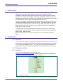
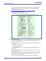
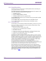
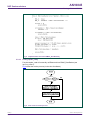
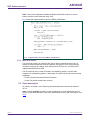
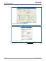
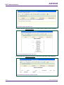
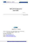
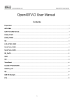
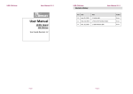
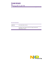
AN10845
Porting uIP1.0 to LPC1700
Rev. 01 — 30 June 2009
Application note
Document information
Info
Content
Keywords
uIP, TCP/IP Stack, LPC1700
Abstract
This application note describes the steps and details of porting uIP (a
light-weight TCP/IP Stack) to LPC1700. A simple web server is
implemented as a demo.
AN10845
NXP Semiconductors
Porting uIP1.0 to LPC1700
Revision history
Rev
Date
Description
01
20090630
Initial version.
Contact information
For additional information, please visit: http://www.nxp.com
For sales office addresses, please send an email to: [email protected]
AN10845_1
Application note
© NXP B.V. 2009. All rights reserved.
Rev. 01 — 30 June 2009
2 of 13
AN10845
NXP Semiconductors
Porting uIP1.0 to LPC1700
1. Introduction
The Ethernet block of LPC1700 contains a full featured 10/100 Mbps Ethernet MAC
designed to provide optimized performance through the use of DMA hardware
acceleration. Features include a generous suite of control registers, half or full duplex
operation, flow control, control frames, hardware acceleration for transmit retry, receive
packet filtering and wake-up on LAN activity. Automatic frame transmission and reception
with Scatter-Gather DMA off-loads many operations from the CPU.
The uIP TCP/IP stack is an extremely small implementation of the TCP/IP protocol suite
intended for embedded systems running low-end 8 or 16-bit microcontrollers. The code
size and RAM requirements of uIP is an order of magnitude smaller than other generic
TCP/IP stacks today. It can only handle a single network interface and contains the IP,
ICMP, UDP and TCP protocols.
This application note describes the steps and details of porting the uIP TCP/IP stack
(latest version is 1.0) to LPC1700. As a demo, a simple web server is implemented and
tested on KEIL MCB1700 board.
Based on this document, users can easily port uIP to other NXP MCU with Ethernet
block.
2. Porting uIP
2.1 Overview
There is no need to make any changes to the actual uIP TCP/IP code, but a device driver
for the target's network device (Ethernet controller/serial port/whatever) has to be written.
The actual system integration part (i.e., the main control loop, which should call the uIP
functions when data arrives and when the periodical timer expires) also has to be done.
2.2 Porting description
2.2.1 Preparation
The uIP can be downloaded from its official website:
http://www.nxp.com/redirect/sics.se/uip. Read the reference manual to understand the
file structure, work flow and especially the main control loop.
Fig 1. File structure of uIP
AN10845_1
Application note
© NXP B.V. 2009. All rights reserved.
Rev. 01 — 30 June 2009
3 of 13
AN10845
NXP Semiconductors
Porting uIP1.0 to LPC1700
It is also useful to be familiar with the LPC Ethernet and Timer blocks by reading the
appropriate sections of the LPC1700 user manual. The latest user manual can be
downloaded from the NXP website:
http://www.standardics.nxp.com/support/documents/microcontrollers/.
2.2.2 Modify porting directory and files
1. Modify the directory name of “unix” to “main”.
2. Create a sub-directory “lpc1700” and add LPC1700 related source file here.
Fig 2. Files in “main” directory (up) and “lpc1700”directory (down)
2.2.3 Porting Timer driver
The timer library provides functions for setting, resetting and restarting timers, and for
checking if a timer has expired.
Two timer functions must be implemented (prototypes are defined in header file “clock.h”
in “uip” directory):
1. clock_time_t clock_time(void);
2. void clock_init(void);
Function clock_time() returns the current system clock time which is measured in
system ticks.
Function clock_init() initializes the clock library and should be called from the main()
function of the system.
The timer driver is implemented in file “clock-arch.h” and “clock-arch.c” (will eventually
call timer functions in lpc17xx_systick.c). The files containing “arch” mean that are
architecture specific implementations.
In this demo, LPC1700 SysTick Timer is used and fired every 10 milliseconds.
AN10845_1
Application note
© NXP B.V. 2009. All rights reserved.
Rev. 01 — 30 June 2009
4 of 13
AN10845
NXP Semiconductors
Porting uIP1.0 to LPC1700
2.2.4 Porting Ethernet driver
The Ethernet library provides functions for initializing Ethernet block, transmitting and
receiving Ethernet frame in LPC1700.
Three Ethernet functions must be implemented which are defined in file “tapdev.h” (with
some minor modifications compared with the original file):
1. void tapdev_init(void);
2. unsigned int tapdev_read(void *pPacket);
3. void tapdev_send(void *pPacket, unsigned int size);
Function tapdev_init() initializes the LPC1700 Ethernet block (including MAC and DMA
controller) and PHY chip.
Function tapdev_read() receives an Ethernet frame from MAC/DMA controller.
Function tapdev_send() transmits an Ethernet frame to MAC/DMA controller.
2.2.4.1 Porting tapdev_init()
Function tapdev_init will eventually call Ethernet driver EMAC_Init (see lpc17xx_emac.c).
After reset, the Ethernet software driver needs to initialize the Ethernet block. During
initialization the software needs to:
1. Remove the soft reset condition from the MAC
2. Configure the PHY via the MIIM interface of the MAC
3. Select RMII or MII mode
4. Configure the transmit and receive DMA engines, including the descriptor arrays
5. Configure the host registers (MAC1, MAC2, etc.) in the MAC
6. Enable the receive and transmit datapaths.
Depending on the PHY, the software needs to initialize registers in the PHY via the MII
Management interface. The software can read and write PHY registers by programming
the MCFG, MCMD, MADR registers of the MAC. The MIIM clock divider ranges from 4 to
28 which will result in a MIIM clock ranging from 0.6 MHz to 4.5 MHz if PCLK is set to
18 MHz. Although IEEE802.3u defines the clock to be no faster than 2.5 MHz, some
PHYs may support the clock up to 12.5 MHz, for example DP83848.
For the physical address of DP83848 (PHY on KEIL MCB1700 board), since the
PHYAD[0] pin has weak internal pull-up resistor and PHYAD[4:1] pins have weak internal
pull-down resistors, the default setting for the PHY address is 00001 (0x1).
After initializing the receive descriptor and status arrays to receive frames from the
Ethernet connection, both the receive DMA controller and receive datapath of the MAC
need to be enabled. To prevent overflow in the receive DMA engine, the receive DMA
engine should be enabled by setting the RxEnable bit in the Command register before
enabling the receive datapath in the MAC by setting the RECEIVE ENABLE bit in the
MAC1 register. See Fig 3.
AN10845_1
Application note
© NXP B.V. 2009. All rights reserved.
Rev. 01 — 30 June 2009
5 of 13
AN10845
NXP Semiconductors
Porting uIP1.0 to LPC1700
Fig 3. Enable receive DMA controller and receive datapath of MAC
2.2.4.2 Porting tapdev_send()
Function tapdev_send will eventually call Ethernet driver EMAC_SendPacket (see
lpc17xx_emac.c).
Fig 4 shows the transmit process (in the view of software only).
Fig 4. Flow chart of transmit process
Note: If the transmit datapath is enabled the Ethernet block will start transmitting the
frame as soon as it detects the TxProduceIndex is not equal to TxConsumeIndex - both
were zero after reset.
Fig 5 shows the implementation of function EMAC_SendPacket.
AN10845_1
Application note
© NXP B.V. 2009. All rights reserved.
Rev. 01 — 30 June 2009
6 of 13
AN10845
NXP Semiconductors
Porting uIP1.0 to LPC1700
Fig 5. Implementation of function EMAC_SendPacket()
2.2.4.3 Porting tapdev_read()
Function tapdev_read will eventually call Ethernet driver EMAC_ReadPacket (see
lpc17xx_emac.c).
Fig 6 shows the receive process (in the view of software).
Fig 6. Flow chart of receive process
AN10845_1
Application note
© NXP B.V. 2009. All rights reserved.
Rev. 01 — 30 June 2009
7 of 13
AN10845
NXP Semiconductors
Porting uIP1.0 to LPC1700
Note: If the receive datapath is enabled the Ethernet block will continue to receive
frames until the receive descriptor array is full.
Fig 7 shows the implementation of function EMAC_ReadPacket.
Fig 7. Implementation of function EMAC_ReadPacket()
2.2.5 Main loop control
The main loop control is in the source file main.c. Before entering the main loop, all
system functions and devices must be initialized, including LPC1700 vector interrupt
controller, serial port (for debug), timer, Ethernet and HTTP server, etc. MAC and IP
address should be also set here.
The uIP stack can be run either as a task in a multitasking system, or as the main
program in a singletasking system. In both cases, the main control loop does two things
repeatedly:
• Check if a packet has arrived from the network
• Check if a periodic timeout has occurred
2.3 Demo description
As a demo, we create a new uVision3 project and implement a web server based on
uIP1.0.
Note: Function snprintf() is used in source file httpd-cgi.c but not implemented in old
version of Keil RealView MDK. In this case, MicroLIB can not be used in the project. See
Fig 8.
AN10845_1
Application note
© NXP B.V. 2009. All rights reserved.
Rev. 01 — 30 June 2009
8 of 13
AN10845
NXP Semiconductors
Porting uIP1.0 to LPC1700
Fig 8. Project options without use of MicroLIB
Modify the IP configuration of your laptop to be in the same LAN with evaluation board.
Fig 9. IP Configuration in laptop
Link and start debug in internal RAM, then type //192.168.0.100 in the address bar of the
web browser. The main page of the uIP web server should now be visible.
AN10845_1
Application note
© NXP B.V. 2009. All rights reserved.
Rev. 01 — 30 June 2009
9 of 13
AN10845
NXP Semiconductors
Porting uIP1.0 to LPC1700
Fig 10. Main page of uIP web sever
Click the hyper-link “Network statistics”, the current network statistics will be displayed:
Fig 11. Network statistics of uIP web server
Click the hyper-link “Network connections”, the current connections will be displayed:
Fig 12. Network connections of uIP web sever
AN10845_1
Application note
© NXP B.V. 2009. All rights reserved.
Rev. 01 — 30 June 2009
10 of 13
AN10845
NXP Semiconductors
Porting uIP1.0 to LPC1700
3. Conclusion
With the success of the Internet, the TCP/IP protocol suite has become a global standard
for communication. For embedded systems, being able to run native TCP/IP makes it
possible to connect the system directly to an intranet or even the global Internet.
Embedded devices with full TCP/IP support will be first-class network citizens, thus being
able to fully communicate with other hosts in the network.
Compared with other TCP/IP stack implementation, uIP consumes a lot less memory
while still providing basic TCP/IP stack capabilities making it suitable for small memory
footprint embedded devices like those in the LPC1700 series.
AN10845_1
Application note
© NXP B.V. 2009. All rights reserved.
Rev. 01 — 30 June 2009
11 of 13
AN10845
NXP Semiconductors
Porting uIP1.0 to LPC1700
4. Legal information
4.1 Definitions
Draft — The document is a draft version only. The content is still under
internal review and subject to formal approval, which may result in
modifications or additions. NXP Semiconductors does not give any
representations or warranties as to the accuracy or completeness of
information included herein and shall have no liability for the consequences
of use of such information.
to result in personal injury, death or severe property or environmental
damage. NXP Semiconductors accepts no liability for inclusion and/or use of
NXP Semiconductors products in such equipment or applications and
therefore such inclusion and/or use is for the customer’s own risk.
Applications — Applications that are described herein for any of these
products are for illustrative purposes only. NXP Semiconductors makes no
representation or warranty that such applications will be suitable for the
specified use without further testing or modification.
Export control — This document as well as the item(s) described herein
may be subject to export control regulations. Export might require a prior
authorization from national authorities.
4.2 Disclaimers
General — Information in this document is believed to be accurate and
reliable. However, NXP Semiconductors does not give any representations
or warranties, expressed or implied, as to the accuracy or completeness of
such information and shall have no liability for the consequences of use of
such information.
4.3 Trademarks
Notice: All referenced brands, product names, service names and
trademarks are property of their respective owners.
Right to make changes — NXP Semiconductors reserves the right to make
changes to information published in this document, including without
limitation specifications and product descriptions, at any time and without
notice. This document supersedes and replaces all information supplied prior
to the publication hereof.
Suitability for use — NXP Semiconductors products are not designed,
authorized or warranted to be suitable for use in medical, military, aircraft,
space or life support equipment, nor in applications where failure or
malfunction of a NXP Semiconductors product can reasonably be expected
AN10845_1
Application note
© NXP B.V. 2009. All rights reserved.
Rev. 01 — 30 June 2009
12 of 13
AN10845
NXP Semiconductors
Porting uIP1.0 to LPC1700
5. Contents
1.
2.
2.1
2.2
2.2.1
2.2.2
2.2.3
2.2.4
2.2.4.1
2.2.4.2
2.2.4.3
2.2.5
2.3
3.
4.
4.1
4.2
4.3
5.
Introduction .........................................................3
Porting uIP ...........................................................3
Overview ............................................................3
Porting description .............................................3
Preparation.........................................................3
Modify porting directory and files........................4
Porting Timer driver............................................4
Porting Ethernet driver .......................................5
Porting tapdev_init() ...........................................5
Porting tapdev_send() ........................................6
Porting tapdev_read() ........................................7
Main loop control................................................8
Demo description ...............................................8
Conclusion.........................................................11
Legal information ..............................................12
Definitions ........................................................12
Disclaimers.......................................................12
Trademarks ......................................................12
Contents.............................................................13
Please be aware that important notices concerning this document and the product(s)
described herein, have been included in the section 'Legal information'.
© NXP B.V. 2009. All rights reserved.
For more information, please visit: http://www.nxp.com
For sales office addresses, email to: [email protected]
Date of release: 30 June 2009
Document identifier: AN10845_1