1
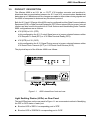
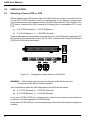
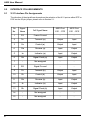
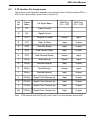
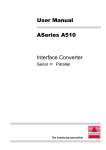
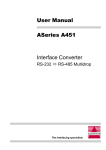
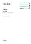
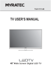
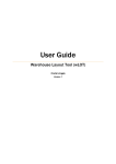
User Manual
ASeries A600
Interface Converter
X.21 ó V.35
The interfacing specialists
A600 User Manual
Version 1.10
May 1999
COPYRIGHTS
All rights reserved. This document may not, in whole or part, be copied, photocopied,
reproduced, translated, or reduced to any electronic medium or machine readable form without
the express permission in writing from Alfatron Pty Ltd.
Copyright 1999 © Alfatron Pty Ltd
DISCLAIMER
Alfatron Pty Ltd has made every attempt to ensure that the information contained in this
document is accurate and complete. Alfatron Pty Ltd makes no representation or warranties of
merchantability or fitness for any particular purpose. Alfatron Pty Ltd reserves the right to make
changes to this document at any time, without notice. Therefore, Alfatron Pty Ltd assumes no
liability for damages incurred directly or indirectly from errors, omissions or discrepancies with
the hardware and the manual.
TRADEMARKS
All Company and Product names are trademarks of the Company or Manufacturer respectively.
WARRANTY
Alfatron warrants its products against defects in materials and workmanship for a period of one
year from receipt by the customer. All warranty is carried out on a return to depot basis unless
an alternative warranty coverage has been arranged.
WARRANTY EXCLUSIONS
The above warranty shall not apply to defects resulting from improper or inadequate
maintenance by the customer, unauthorised modifications or misues, operation outside the
environmental specifications for the product, damage due to power surges, lightening strikes or
any other phenomenon outside normal operational specifications.
Alfatron Pty Ltd ACN: 005 410 819
P.O. Box 4161
Unit 9/36 New St.
Ringwood VIC 3134
AUSTRALIA
Web Site: www.alfatron.com.au
A600 User Manual
1.0
PRODUCT DESCRIPTION
The ASeries A600 is an X.21 bis <> CCITT V.35 interface converter and provides bidirectional data communication between the X.21 and V.35 communication standards at
data rates up to 2 Mbits/second. No changes are made to either data or timing signals and
the A600 is transparent to data and any introduced protocol.
Both the X.21 and V.35 ports of the A600 may be configured to either Data Communications
Equipment (DCE) or Data Terminal Equipment (DTE) via an internal 50-pin jumper. Internal
jumpers are also used for the selection of Clock Sources and Handshaking lines. Possible
A600 configurations are as follows:
l V.35 (DCE) to X.21 (DTE)
in this configuration the X.21 Control Signal source is jumper selected between either
V.35 Request To Send (RTS) or V.35 Data Terminal Ready (DTR).
l V.35 (DTE) to X.21 (DCE)
in this configuration the X.21 Signal Timing source is jumper selected between either
V.35 Serial Clock Transmit (SCT) or V.35 Serial Clock Receive (SCR).
The physical layout of the ASeries A600 is as follows:
Figure 1-1
A600 viewed from front and rear
Light Emitting Diodes (LEDs) on Rear Panel
The two LEDs shown on the rear panel in Figure 1-1 are a convenient method of identifying
the DTE or DCE status of each port:
l Bi-colour LED is 'RED' if corresponding port is 'DTE'.
l Bi-colour LED is 'GREEN' if corresponding port is 'DCE'.
1
A600 User Manual
2.0
INSTALLATION
2.1
Selecting a Port as DCE or DTE
Before installing the A600 please make sure that the 50-pin jumper is inserted into the
correct DCE or DTE position to meet your requirements. In the majority of cases when
synchronous serial communications is used, the DCE will provide the 'Clock Signal' to the
DTE device, therefore the A600 supports the following two configurations of X.21 and
V.35:
(i)
X.21-DTE (Terminal) to V.35-DCE (Modem)
(ii)
X.21-DCE (Modem) to V.35-DTE (Terminal)
these configurations are selected by removing the cover of the A600 and inserting the 50pin jumper into the appropriate socket, J201 or J202, located on the Printed Circuit Board
(PCB) of the A600 as shown below:
Figure 2-1 Configuration jumper blocks on A600 PCB
WARNING: 240Volt power must be removed from the A600 before the cover
is removed and the 50-pin jumper re-located.
Two combinations which are NOT supported by the A600 are as follows:
(iii)
X.21-DTE (Terminal) to V.35-DTE (Terminal)
(iv) X.21-DCE (Modem) to V.35-DCE (Modem)
In the case of DTE to DTE (iii), no timing source exists for synchronous communications
as timing is normally supplied by the DCE device.
In the case of DCE to DCE (iv), there are two timing sources which will create an ambiguous
situation.
2
A600 User Manual
2.2
Selecting V.35 Clock Source
The V.35 interface has two differential clock sources, Serial Clock Transmit (SCT) and
Serial Clock Receive (SCR). In the X.21 (DCE) to V.35 (DTE) case, one of the two clock
sources must be selected as a source for the X.21 interface Signal Element Timing signal.
Because the clock source is a differential signal it requires two lines. Therefore the A600
provides a pair of jumper blocks, J203 and J204 (shown in Figure 2-2), to select the two
lines. These jumpers must always be moved as a pair.
To select V.35 (SCT) as the clock source, move the pair of jumpers to the 'TxCLK' position.
To select V.35 (SCR) as the clock source, move the pair of jumpers to the 'RxCLK' position.
The factory default setting is V.35 (SCT) with jumpers in the 'TxCLK' position.
Figure 2-2
2.3
Selecting V.35 Handshaking Lines
The X.21 interface Control line is used to drive the V.35 interface DTR or RTS handshaking
lines. The J205 jumper block has two positions to define which of the handshaking lines,
DTR or RTS, is driven by the X.21 Control line.
The settings for J205 are shown in Figure 2-3 and are used in the following two situations:
(a)
if the A600 is set for X.21 (DCE) and V.35 (DTE) then the jumper in J205 may be
set for either DTR or RTS, according to your requirements.
(b)
if the A600 is set for X.21 (DTE) and V.35 (DCE) then the jumper in J205 must be
set to the RTS position.
In both cases the line which is not selected is pulled to +12V via a 4.7KW resistor.
The factory default for jumper J205 is the RTS position.
Figure 2-3
3
A600 User Manual
2.4
Front Panel LED Indicators
The LED indicators in the A600 provide a function similar to that of a breakout box. They
show the level of the appropriate TTL signal rather than a level directly present on the
communications line. The signal names correspond to the port which is selected as DTE.
For example, if the A600 is configured as X.21 (DTE) / V.35 (DCE) and the 'RD' LED is
active then this refers to the activity on the X21 port 'Ra / Rb' line pair.
The advantage of this approach is that all communication line signals are converted
internally by the A600 to TTL levels and then converted to a level specific to either the
X.21 or V.35 interface. The TTL level signals therefore provide a common reference to
both ends of the converter and show the signals as seen by the converter regardless of
the type of interface configuration.
The A600 has six LED indicators on its front panel. The LED marked 'Power' is Yellow and
indicates that the A600 has operating power. The other five LEDs are Red/Green bi-colour
indicators with the following meanings:
Configured for X.21 (DCE) and V.35 (DTE)
l Clock - Data Clock signal from V.35 lines STR(a/b) or SCT(a/b)
l DCD - Data Carrier Detect from V.35 device
l RTS - Handshaking signal to V.35 device, RTS or DTR
l RD - Data received from V.35 device
l TD - Data sent to V.35 device
Configured for X.21 (DTE) and V.35 (DCE)
l Clock - Data Clock signal from X.21 line S(a/b)
l IND - Indicator signal to X.21 device
l CTRL - Control signal to V.35 device
l RD - Data received from X.21 device
l TD - Data sent to X.21 device
The convention used on these bi-colour LEDs is as follows:
l Bi-colour LED is 'RED' if corresponding TTL signal is 'HIGH'.
l Bi-colour LED is 'GREEN' if corresponding TTL signal is 'LOW'.
4
A600 User Manual
2.5
Rear Panel LED Indicators
The two bi-colour LEDs on the rear panel are shown in Figure 1-1. They identify the DTE
or DCE status of the port closest to that LED and are determined by the internal 50-pin
jumper. These LEDs provide a convenient method of identifying the status of each port
without opening the case:
l Bi-colour LED is 'RED' if corresponding port is 'DTE'.
l Bi-colour LED is 'GREEN' if corresponding port is 'DCE'.
3.0
CABLE REQUIREMENTS
Alfatron Pty Ltd recommends the use of shielded cable with all of its products. Shielding
reduces Electro Magnetic Radiation and improves noise immunity. This helps minimise
interference to other equipment and will improve communications reliability.
The recommended cable construction is as follows:
l Take the shield (surrounding cable wires) and solder it to the Frame Ground (FG) pin.
If FG is not available, use Signal Ground (SG) but in this case always use a separate
wire for ground which is connected at both ends.
If a metalised backshell is used then it is preferred that the cable shield make 360o
contact with the backshell at the point of entry.
l The shield must be connected at both ends of the cable.
4.0
FACTORY SETTINGS
The A600 is factory pre-set to the following configuration:
l X.21 (DCE) to V.35 (DTE)
l V.35 Clock Source (J203 and J204) is set to 'TxCLK'
l V.35 Handshaking Line (J205) is set to RTS
5
A600 User Manual
5.0
INTERFACE PIN ASSIGNMENTS
5.1
X.21 Interface Pin Assignments
The direction of the signal lines depends on the selection of the X.21 port as either DTE or
DCE via the 50-pin jumper, please refer to Section 2.1.
6
3LQ
1R
6LJQDO
1DPH
)XOO6LJQDO1DPH
$3RUW
;'7(
$3RUW
;'&(
)*
)UDPH*URXQG
7D
7UDQVPLWD
2XWSXW
,QSXW
&D
&RQWUROD
2XWSXW
,QSXW
5D
5HFHLYHD
,QSXW
2XWSXW
,D
,QGLFDWRUD
,QSXW
2XWSXW
6D
6LJQDO&ORFND
,QSXW
2XWSXW
1RWDVVLJQHG
6*
6LJQDO*URXQG
7E
7UDQVPLWE
2XWSXW
,QSXW
&E
&RQWUROE
2XWSXW
,QSXW
5E
5HFHLYHE
,QSXW
2XWSXW
,E
,QGLFDWRUE
,QSXW
2XWSXW
6E
6LJQDO&ORFNE
,QSXW
2XWSXW
1RWDVVLJQHG
1RWDVVLJQHG
A600 User Manual
5.2
V.35 Interface Pin Assignments
The direction of the signal lines depends on the selection of the V.35 port as either DTE or
DCE via the 50-pin jumper, please refer to Section 2.1.
3LQ
1R
6LJQDO
1DPH
)XOO6LJQDO1DPH
$3RUW
9'7(
$3RUW
9'&(
$
)*
)UDPH*URXQG
%
6*
6LJQDO*URXQG
&
576
5HTXHVW7R6HQG
2XWSXW
,QSXW
'
&76
&OHDU7R6HQG
,QSXW
2XWSXW
(
'65
'DWD6HW5HDG\
,QSXW
2XWSXW
)
'&'
'DWD&DUULHU'HWHFW
,QSXW
2XWSXW
+
'75
'DWD7HUPLQDO5HDG\
2XWSXW
,QSXW
3
6'D
6HQG'DWDD
2XWSXW
,QSXW
5
5'D
5HFHLYH'DWDD
,QSXW
2XWSXW
6
6'E
6HQG'DWDE
2XWSXW
,QSXW
7
5'E
5HFHLYH'DWDE
,QSXW
2XWSXW
9
6&5D
6LJQDO&ORFN5HFHLYHD
,QSXW
2XWSXW
;
6&5E
6LJQDO&ORFN5HFHLYHE
,QSXW
2XWSXW
<
675D
6LJQDO&ORFN7UDQVPLWD
,QSXW
2XWSXW
$$
675E
6LJQDO&ORFN7UDQVPLWE
,QSXW
2XWSXW
Note:
DTE external clock (SCTE) pair, pins U and W, is not supported by the A600.
7
A600 User Manual
6.0
SPECIFICATIONS
X.21 Port:
X.21 bis
Select as DTE or DCE
DB-15 female connector
V.35 Port:
CCITT V.35 Compatible
Select as DTE or DCE
34-pin V.35 female connector
Front LED Indicators:
Clock
X.21 (IND) / V.35 (DCD)
X.21 (CTRL) / V.35 (RTS)
Receive Data X.21 and V.35
Transmit Data X.21 and V.35
Power
Rear LED Indicators:
X.21 Port Status, DTE or DCE (Bi-colour Red/Green)
V.35 Port Status, DTE or DCE (Bi-colour Red/Green)
Power Supply:
240V AC 50Hz
Standard IEC male socket
Dimensions:
45mm x 120mm x 190mm
Weight:
920 grams
Operating Temperature:
0° to 40° C
Stroage Temperature:
(Bi-colour Red/Green)
(Bi-colour Red/Green)
(Bi-colour Red/Green)
(Bi-colour Red/Green)
(Bi-colour Red/Green)
(Yellow)
-20° to 70° C
All specifications subject to change without notice
8
N42
DECLARATION OF CONFORMITY
according to the European Commissions EMC Directive 89/336/EEC
We,
of,
Name of Manufacturer:
Address of Manufacturer:
Australian Company Number:
ALFATRON PTY. LTD
UNIT 9, 36 NEW ST.
RINGWOOD VIC 3134
AUSTRALIA
ACN: 005 410 819
declare under sole responsibility that the product:
Product Name:
ASeries X.21 to V.35
Interface Converter
Model Number:
A600
to which this declaration relates is in conformity with the following standards:
CISPR-22 / EN 55022 class B
IEC 801-2 / prEN55024-2
IEC 801-3 / prEN55024-3
IEC 801-4 / prEN55024-4
EMI from Information Technology Equipment (ITE)
Electro Static Discharge Immunity
Radiated RF Immunity
Electrical Fast Transients Immunity