1
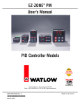
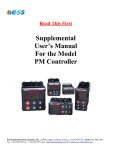
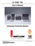
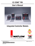
EZ-ZONE® Security Lockout ® There are three levels of security on the EZ-ZONE controller family. ® The lowest level of security is when Password Enable is turned ‘Off’ and is defined as: EZ-ZONE Security Clearance. This low level is explained in more detail, in Chapter 1 of this white paper. The middle level of security is when the Password Enable is turned ‘On’ and the Rolling Password is turned ‘Off’. ® This is defined as: EZ-ZONE Security Lockout, Mid Level. This mid level is explained in more detail in Chapter 2 of this white paper. The highest level of security is when the Password Enable is turned ‘On’, and the Rolling Password is turned ‘On’. ® This is defined as: EZ-ZONE Security Lockout, High Level. This high level is explained in more detail in Chapter 3 of this white paper. When security is applied, it applies to both the keypad entry as well as connection from a PC using EZ-ZONE Configurator software via Standard Bus protocol on the EIA-485 port. Watlow 1241 Bundy Blvd Winona, MN 55987 Telephone (507) 494-5656 2010 Watlow Electric Manufacturing Company 1 DS 07/2012 EZ-ZONE® Security Lockout CHAPTER 1: EZ-ZONE® Security Clearance. ® Let’s explain how the EZ-ZONE Security Lockout with the Password Enable turned ‘Off’ operates. ® The EZ-ZONE parameters are located in nine different groups. These groups are: 1. Home Page 2. Setup Page 3. Factory Page 4. Diagnostic Menu - independent from but located under the Factory Page 5. Lockout Menu - independent from but located under the Factory Page 6. Calibration Menu - independent from but located under the Factory Page 7. Custom Menu - independent from but located under the Factory Page 8. Operations Page 9. Profile Page Of these nine groups, the first seven of these groups have a fixed Security level. The fixed Security levels for these seven groups are: 1. The Home Page : 1 2. The Setup Page : 4 3. The Factory Page : 1 4. The Diagnostic Menu - independent from but located under the Factory Page : 1 5. The Lockout Menu - independent from but located under the Factory Page : 1 6. The Calibration Menu - independent from but located under the Factory Page : 5 7. The Custom Menu - independent from but located under the Factory Page : 5 The remaining two of these nine groups have an adjustable Security level. The default value and range for the two groups are: 1. The Operations Page: Default is 2 with a Range of 1 – 3. 2. The Profile Page: Default is 3 with a Range of 1 – 3. These two prompts are located at the Factory Page > Lockout menu. To reach this Page > Menu press the Advance Key and the Infinity Key (Reset Key on select models) at the same time until [FCtY] is displayed on the green display. Then press the down arrow key until [`LoC] is displayed on the red display. Press the Advance Key and the [LoC;o] prompt will be on the green display. A value of 1 to 3 will be displayed on the red display and this is the security level for the operations page. Another press of the Advance Key and [LoC;P] prompt will be on the green display on models with profiling. A value of 1 to 3 will be displayed on the red display and this is the security level for the profile page. Now we know what the security level numbers for are each group, but what significance do these numbers mean? This security level number is compared to the Read Lockout Security number and the Set Lockout Security number. If the Read Lockout Security number is greater than or equal to the security level number of the particular group, then that particular group can be read (viewed). And if the Read Lockout Security number is less than the security level number of the particular group, then that particular group cannot be read (hidden). If the Set Lockout Security number is greater than or equal to the security level number of the particular group, then that particular group can be written (changed). And if the Set Lockout Security number is less than the security level number of the particular group, then that particular group cannot be written (not changed). Watlow 1241 Bundy Blvd Winona, MN 55987 Telephone (507) 494-5656 2010 Watlow Electric Manufacturing Company 2 DS 07/2012 EZ-ZONE® Security Lockout Another way to look at it is that you have 5 different door keys, (labeled 1,2,3,4, and 5). If you only have the #1 door key, you can only enter doors that are labeled #1 for its security level. Whereas if you have the #5 door key then you can access any of the doors labeled 1, 2, 3, 4 or 5. A higher number provides more access. Keep in mind that there are two different sets of keys. One set of keys is used to allow parameters in given menus to be read (viewed) and the other set of keys is used to allow parameters in given menus to be written (changed). The set of keys that allows it to read is called the Read Lockout Security Number and the set of keys that allow it to written is called the Set Lockout Security number. The prompts for these two keys are located at the Factory Page > Lockout Menu. To reach this menu press the Advance Key and the Infinity Key at the same time until [FCtY] is displayed on the green display. Then press the down arrow key until [LoC] is displayed on the red display. Press the Advance Key three times, and the [rLoC] prompt will be on the green display. A value of 1 to 5 will be on the red display, (default is 5). This is the Read Lockout value. Press the Advance Key again and the [SLoC] prompt will be on the green display. A value of 0 to 5, will be on the red display, (default is 5). This is the Set Lockout Value. If a value of 0 is entered then, then no changes are allowed to any parameters, except to this parameter – [SLoC]. Example 1 A customer would like to read (view) parameters on the Operations Page, but keep it from been written (changed). They want to be able to keep the Setup Page, the Calibration Menu, and the Custom Menu from being read (viewed) and written (changed). The customer also wants to be able to read and write to the Home Page, Diagnostics Menu, Lock Menu and Profiling Page. To accomplish this you can set the: [LoC;O] = 2, [LoC;P] = 3, [rLoc] = 3, [SLoc] = 3. Example 2 A customer would like to Read (view) any parameter, but not allow any to be written (changed). To accomplish this you can set the: [LoC;O] = 2, [LoC;P] = 3, [rLoc] = 5, [SLoc] = 0. Watlow 1241 Bundy Blvd Winona, MN 55987 Telephone (507) 494-5656 2010 Watlow Electric Manufacturing Company 3 DS 07/2012 EZ-ZONE® Security Lockout Watlow 1241 Bundy Blvd Winona, MN 55987 Telephone (507) 494-5656 2010 Watlow Electric Manufacturing Company 4 DS 07/2012 EZ-ZONE® Security Lockout CHAPTER 2: EZ-ZONE® Security Lockout, Mid Level The mid level of security is when the Password is turned ‘On’ and the Rolling Password is turned ‘Off’. 1. To activate this level of security, go to the Factory Page > Lock Menu. 2. Set the Password Enable to ‘On’ and the Rolling Password to ‘Off’. 3. Set the desired User and Administrator Password numbers. 4. **** These numbers, the User and Administrator Password, are very important and need to be documented. Once the Lock menu is exited or power to the controller is turned off, these numbers and the Lock Menu are no longer accessible****. 5. Passwords need to be remembered. If you feel that the password cannot be remembered, then this is the incorrect level of security to utilize. 6. For this white paper we will use the default passwords. User Password = 63 and Admin. Password = 156. 7. For this level of security, four other parameters must also be set. They are the Operations Page, the Profiling Page, the Read Lock, and the Locked Access Level. For this white paper, let’s set them to 2, 3, 3, and 2 respectively. Watlow 1241 Bundy Blvd Winona, MN 55987 Telephone (507) 494-5656 2010 Watlow Electric Manufacturing Company 5 DS 07/2012 EZ-ZONE® Security Lockout ® 8. Remove power from the EZ-ZONE and re-apply power. We now have three different possible scenarios. a. Operator does not know the User Password or Administrator Password. b. Operator does know the User Password, but does not know the Administrator Password. c. Operator does know the User and Administrator Password. 9. Since we removed and reapplied power, the displayed Password has been Reset to 0. This password is located at the Factory Unlock menu. 10. So let’s look at the first scenario, in which the Operator does not know the User Password or Administrator Password. a. In this scenario, the operator will only have access to the parameters that are defined by the Locked Access Level; which we set to 2. Watlow 1241 Bundy Blvd Winona, MN 55987 Telephone (507) 494-5656 2010 Watlow Electric Manufacturing Company 6 DS 07/2012 EZ-ZONE® Security Lockout b. If the Locked Access Level is equal to or greater than the Security level number of that particular group; then that group is accessible. c. There are nine different pages and menus. Of these nine groups, the first seven of these groups have a fixed Security level. The fixed Security levels for these seven groups are: 1. Home Page : 1 2. Setup Page : 4 3. Factory Page : 1 4. Diagnostic Menu - independent from but located under the Factory Page : 1 5. Lockout Menu - independent from but located under the Factory Page : 1 6. Calibration Menu - independent from but located under the Factory Page : 5 7. Custom Menu - independent from but located under the Factory Page : 5 d. The remaining two of these nine groups have an adjustable Security level. The default and range for these two groups are: 1. The Operations Page: Default is 2 and Range is 1 – 3. Which we set to 2, as shown above. 2. The Profile Page: Default is 3 Range is 1 – 3. Which we set to 3, as shown above. e. Now using EZ-ZONE Configurator we can see, when looking at the unlock submenu, that the password is set to 0, showing that the User does not know the password. See Screen Capture labeled “e”. f. Looking at the Pages and Menu’s that are accessible, these are Pages > Menus that have a number of 2 of less. This is because earlier we set the Locked Access Level to 2. 1. Operations Page is accessible. See Screen Capture labeled “f i”. 2. Factory Page is accessible. See Screen Capture labeled “f ii”. 3. Diagnostics Menu is accessible. See Screen Capture labeled “f iii”. g. Looking at the Pages and Menu’s are not accessible, these are the Pages > Menus that have a number greater than 2; since earlier we set the Locked Access Level to 2. Notice in the screen capture that these Pages > Menus are not visible on the screen capture for EZ-ZONE Configurator. 1. Setup Page is not accessible. 2. Calibration Menu is not accessible. 3. Custom Menu is not accessible. 4. Profile Page is not accessible. Watlow 1241 Bundy Blvd Winona, MN 55987 Telephone (507) 494-5656 2010 Watlow Electric Manufacturing Company 7 DS 07/2012 EZ-ZONE® Security Lockout 11. So let’s look at the second scenario, in which the Operator does know the User Password, but does not know the Administrator Password. a. In this scenario, the operator will have not have access to the Factory Lock and will be limited to what the administrator had set. This is defined by the Read Lockout Level parameter; which we set to 3. b. If the Read Lockout Level is equal to or greater than the Security level number of that particular group, then that group is accessible. c. The operator enters the proper User Password in the unlock menu; which for this white paper is set to 63. d. Looking at what Pages > Menus are accessible, for this white paper, these are the Pages > Menus that have a number of 3 or less. This is because earlier we set the Read Lockout Level to 3. 1. Operations Page is accessible. 2. Factory Page is accessible. 3. Diagnostics Menu is accessible. 4. Profile Page is accessible e. Looking at what Pages > Menus are not accessible, these are the Pages > Menus that have a number greater than 3. This is because earlier we set the Read Lockout Level to 3. 1. Setup Page is not accessible. 2. Calibration Menu is not accessible. 3. Custom Menu is not accessible. 12. So let’s look at the third scenario, in which the Operator does know the Administrator Password. a. In this scenario, when the operator enters the Administrator Password in the unlock menu, which for this white paper is 156, means that they will have access to all the parameters. The lock menu is now accessible for the Administrator. The Password Enable, Rolling Password, Read Lock, Write Lock and entering new Passwords are accessible. Watlow 1241 Bundy Blvd Winona, MN 55987 Telephone (507) 494-5656 2010 Watlow Electric Manufacturing Company 8 DS 07/2012 EZ-ZONE® Security Lockout b. The Read Lock parameter is located in the Lock Menu and its function is described in Chapter 1 of this White Paper. c. Therefore, if the Read Lock parameter is not set to 5, the Administrator has access to the Lock Menu; where the Read Lock can be changed. Watlow 1241 Bundy Blvd Winona, MN 55987 Telephone (507) 494-5656 2010 Watlow Electric Manufacturing Company 9 DS 07/2012 EZ-ZONE® Security Lockout CHAPTER 3: EZ-ZONE® Security Lockout, High Level Highest level of security is when the Password is turned ‘On’, and the Rolling Password is turned ‘On’. 1. To activate this level of security, go to the Factory Page, and the Lock Menu. 2. Set the Password Enable to ‘On’, and Rolling Password to ‘On’. 3. Set the User and Administrator Password numbers. 4. **** These numbers, the User and Administrator Passwords, are very important and need to be documented. Once the Lock menu is exited or power to the controller is turned off, these numbers and the Lock Menu are no longer accessible****. 5. Passwords need to be remembered. If you feel that the password cannot be remembered, then this is the incorrect level of security to utilize. 6. The rolling password utilizes the “Public Key”, (Code) parameter. This “Public Key”, (Code) parameter will change or roll to a new number every time power is cycled. This “Public Key”, (Code) is a variable in a formula to determine what the correct password will be. Then when this correct password is entered; it will allow a User or an Administrator to gain access. 7. Once the password is entered, exit the factory menu using the Infinity Key (Reset Key on some models). Then re-enter the factory key to obtain access to the Lock menu. Cycling power to the controller will reenable the password entry requirement. When rolling password is enabled, the password requires a new temporary number based on the formula. 8. The User’s Manual contains the formula to generate a temporary password based on the original master password and the displayed code. This allows an OEM to provide temporary access to a specific controller without having to divulge the original master password used by all products shipped. 9. It is possible to gain access to a controller that was accidently enabled by contacting Watlow Technical Support at (507) 494-5656. Provided that the password was not entered by an OEM, the Technical Support person will generate a temporary password. Watlow 1241 Bundy Blvd Winona, MN 55987 Telephone (507) 494-5656 2010 Watlow Electric Manufacturing Company 10 DS 07/2012