1
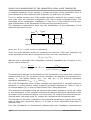
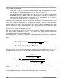
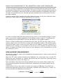
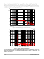
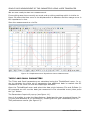
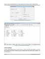
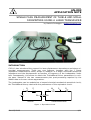
AN-003 APPLICATION NOTE AUDIOMATICA SINGLE PASS MEASUREMENT OF THIELE AND SMALL PARAMETERS USING A LASER TRANSDUCER by Daniele Ponteggia - [email protected] INTRODUCTION CLIO 10 has introduced the support for laser displacement transducers and stereo si nusoidal measurements. These two new features, together with the I Sense impedance measurement mode, allows to measure in a single sinusoidal sweep the impedance and the displacement as function of frequency of the loudspeaker under test. Consequently, this allows to obtain the Thiele&Small driver parameters in a single pass, instead of the two measurements plus post-processing required by the added mass or known volume approaches. The loudspeaker can be modeled as a lumped electrical-mechanical-acoustical circuit, the Thiele&Small theory deals with the parameters of this equivalent circuit. i e RE ZL + u Bl·u electrical + + MMS CMS RMS Bl·i mechanical/acoustical Figure 1: Equivalent Circuit AN-003/1209 1/11 SINGLE PASS MEASUREMENT OF T&S PARAMETERS USING LASER TRANSDUCER A complete treatment of the subject is outside the scope of this application note, a good reference on the subject are the D'Appolito [1] and Leach [2] books. From its earliest versions the CLIO system allowed to measure the complex impedance seen from the electrical loudspeaker port with a single sinusoidal sweep. The knowledge of the loudspeaker impedance (in free air) it is not sufficient to the com plete identification of the parameters of the previous equivalent circuit. The impedance measurement allow only the identification of the parameters of the electrical equivalent circuit: I(jω) RE ZL(jω) + LCES E(jω) CMES RES Figure 2: Equivalent Circuit of Electrical Impedance where the Z L j is the voice coil inductance. There are some different models to represent this element, CLIO uses internally the Leach equivalent circuit which represent the voice coil lossy inductance as: n Z L j = j LE Without loss of generality the loudspeaker electrical impedance as a function of frequency can be wrote as: Z j = E j =RE Z L j I j j LCES 2 j L CES C MES j LCES 1 RES The parameters that can be calculated from the impedance curve (and with a previous measurement of the R E coil direct current resistance) are basically the resonance frequency f s , the quality factors Q MS , Q ES and Q TS or the motional impedance equivalent parameters C MES , LCES and R ES . The CLIO Thiele&Small menu renders available two algorithms to calculate these parameters: by points using a widely accepted procedure described by Thiele in one of its seminal papers [3] or using a Least Square Error fitting algorithm. The parameters calculated using the electrical equivalent impedance circuit are linked to the parameters of the complete electrical-mechanical-acoustical equivalent circuit by means of two conversion factors: the force factor Bl couples the electrical and mechanical parts, the piston area SD couples the mechanical and acoustical parts. The estimate of the other mechanical and acoustical parameters requires the knowledge of these two conversion factors, or at least of other parameters that allow to calculate them. Prior the introduction of simultaneous displacement and impedance measurements 2/11 www.audiomatica.com SINGLE PASS MEASUREMENT OF T&S PARAMETERS USING LASER TRANSDUCER CLIO used two approaches: – Single free air driver impedance measurement and knowledge of the piston area SD and one parameter between M MS , M MD , C MS and Bl – Two impedance measurements with the second carried out with a known mass attached to the cone (added mass) or with the driver mounted in a known volume enclosure (known volume). Knowledge of the piston area SD is required to calculate the parameters of the acoustical part. Usually a prior knowledge of the key mechanical parameters is not available, thus it is necessary to rely on the latter approach and perform a second impedance measurement. The resonant frequency of the system changes from the free air case, measuring the shift lead to the estimate of the moving mass in the added mass case and the compliance in the known volume case. Both techniques have their pros and cons, but both require the manual intervention of the operator to put the mass into the cone or to mount the speaker on a box. With the introduction in CLIO 10 of the stereo sinusoidal measurement and the support of the laser displacement sensor, it is possible in a single pass to collect the loudspeaker impedance and displacement. The displacement as function of frequency can be calculated putting into a system the equations of the electrical and mechanical/acoustical loudspeaker equivalent circuit parts: { E j = RE Z L j j LCES L j L CES C MES j CES 1 RES 2 I j E j = RE Z L j I j Bl j X j then the current can be eliminated from the system and the displacement X j can be expressed as a function of the Thiele&Small parameters and the driving voltage E j : j LCES LCES 1 R ES 1 X j = E j j Bl j LCES R E Z L j L 2 j LCES CMES j CES 1 R ES 2 j LCES CMES j The force factor Bl can be directly estimated fitting the model to the displacement curve. The method has the great benefit that can be performed in a single measurement sweep and doesn't need to modify the loudspeaker free air mounting. 3/11 www.audiomatica.com SINGLE PASS MEASUREMENT OF T&S PARAMETERS USING LASER TRANSDUCER MEASUREMENT SETUP In order to perform the measurements described in this document the following material is needed: – Audiomatica CLIO FW-01 box – Audiomatica QCBox model V – CLIO 10 software – Displacement laser sensor with analog voltage output (a sensor with a measurement range of ±20 mm and a resolution of at least 0.02 mm and a bandpass around 1 kHz is adequate) In our tests we used a Baumer OADM 20I6441/S14F (this sensor can be supplied by Audiomatica with a cabling set suitable for R&D usage with CLIO), the sensor has a measuring range from 30..70 mm with a voltage output swinging 0..10 V. The displacement sensor sensitivity in [ V /m ] can be calculated as: sensitivity = 10 =250 [ V /m ] 0.040 This data must be entered into the CLIO options under the Units Conversion tab as showed in figure 3. Figure 3: CLIO Options Units Conversion Window The laser sensor should be connected to the QCBox input 4, which is capable of measuring also DC voltages in the range 0..5 V, this will help to put the laser sensor in place into its operating range. 4/11 www.audiomatica.com SINGLE PASS MEASUREMENT OF T&S PARAMETERS USING LASER TRANSDUCER LASER CLIOQC AUDIOMATICA D.U.T. 1 2 3 4 I SENSE TO CLIO FROM CLIO A IN B A OUT B Figure 4: Measurement Setup The connection between CLIO FW-01, the QCBox model V, the loudspeaker under test and the laser sensor should be (see figure 4): – QCBox “to CLIO” output connected to CLIO FW-01 input A – QCBox “I sense” output connected to CLIO FW-01 input B – CLIO FW-01 output A connected to QCBox “from CLIO” input – Laser sensor output connected to QCBox input 4 (the laser need also to be connected to a power supply in order to operate) – Loudspeaker terminals connected to the QCBox “D.U.T.” power output Once the connections are in place it is necessary to instruct CLIO to route the QCBox model V input 4 to the CLIO FW-01 input A. This can be done using the QCBox&LPT control panel as in the following figure: Figure 5: QCBox Input Channel Selection The routing is now completed, the laser sensor must be placed in front of the loudspeaker diaphragm, at the sensor focal distance which in our case is between 30 and 5/11 www.audiomatica.com SINGLE PASS MEASUREMENT OF T&S PARAMETERS USING LASER TRANSDUCER 70 mm. A proper loudspeaker mounting must be provided and the laser sensor must be perfectly orthogonal to the cone plane. The laser should be pointed at the center of the dome (if available, otherwise should be pointed towards a loudspeaker part which is rigidly moving with the coil), a white dot can be drawn with a white pencil to help the laser reading. Please be careful when handling the laser distance sensor, since even relatively small amounts of laser light can lead to permanent eye injuries. Figure 6: QCBox V DC reading panel In order to help to place the laser sensor at the center of its operating range it is possible to use the DC reading capability of the QCBox model V input 4. To activate the DC reading use the QCBox&LPT controls tab specific to the QCBox model V. Since no signal conditioning is provided with this laser, we will use only half of its operating range, from 30 to 50 mm to match with the QCBox model V DC reading range. Moving the laser closer to the cone will lower the DC reading, moving it away will in crease the DC reading. It is possible to use the IN 4 DC reading to place the laser sensor at about one fourth of its range (40 mm distance), this corresponds to a IN 4 DC reading of 2.50 V. DISPLACEMENT MEASUREMENTS We are now ready to collect a first displacement measurement to get in touch with the new CLIO features. Open the FFT menu, select channel A and “dBmeter” as y-axis scale, then run the FFT. Adjust the input sensitivity to -40dBV. We should see the noise floor captured by the laser displacement sensor (see figure 7). Note that above 1kHz there are strong artifacts due to the sensor DAC output, but since there are outside the band of the sensor and at low level these effects can be neglected. A short note on the y-axis units is needed, the reading in dBmeter is the RMS displacement captured by the sensor expressed in decibels units referred to 1 meter. To convert to and from dBmeters and meters: x dBmeter =20log 6/11 x m 1m x m =10 x dBmeter 20 www.audiomatica.com SINGLE PASS MEASUREMENT OF T&S PARAMETERS USING LASER TRANSDUCER If we generate a low frequency sinewave while running the FFT analysis we should get a situation similar to one depicted in figure 8. FFT 1-29-2010 3.29.23 PM -60.0 dBmeter -80.0 -100.0 -120.0 -140.0 -160.0 10 20 50 100 200 500 1k Hz 2k 5k 10k 20k CH A dBmeter 48kHz 16384 2.93Hz Rectangular Unsmoothed File: noise_floor.fft Figure 7: Laser Displacement Sensor Noise Floor FFT 1-29-2010 3.32.11 PM -40.0 dBmeter -60.0 -80.0 -100.0 -120.0 -140.0 10 20 50 100 200 500 1k Hz 2k 5k 10k 20k CH A dBmeter 48kHz 16384 2.93Hz Rectangular Unsmoothed File: 100Hz_-15dBu.fft Figure 8: 100 Hz Sinewave Displacement It is also possible to check the displacement readings using the Multimeter Menu, here selecting “Displacement” is it possible to see the results in terms of RMS, peak and peak-to-peak values. 7/11 www.audiomatica.com SINGLE PASS MEASUREMENT OF T&S PARAMETERS USING LASER TRANSDUCER MEASURING DISPLACEMENT AND IMPEDANCE We suppose here that the reader is familiar with impedance measurements using CLIO and the QCBox I Sense mode. The CLIO FW-01 input B is already connected to the QCBox I Sense output. To proceed with displacement and impedance simultaneous measurement, open the Sinusoidal menu. Select “CH A&B” as inputs and “dBmeter” as Y scale unit, then into the Sinusoidal set tings check the “Ohm Right Scale” and “QCBox Select” options (see figure 9). Figure 9: Sinusoidal Settings for Displacement and Impedance Measurement Check the output output level, this will affect the voltage at which the measurement is performed. Please be aware of the fact that the output level is a tradeoff between two opposed demands. Measurement SNR asks for high levels while Thiele&Small small signal model theory require low levels in order not to push the loudspeaker into its non-linear range. Common CLIO FW output levels (balanced) that can be adopted using the previously described laser displacement sensor and the QCBox model V amplifier are ranging between 0.05 V and 0.25 V. Check also the input gain levels for both channels A (displacement) and B (current), a proper setting is very important in order to get reliable results. In our example here we used a non-stepped sinusoidal sweep with 1/24 octave resolution and frequency range from 22388 Hz to 10 Hz. 8/11 www.audiomatica.com SINGLE PASS MEASUREMENT OF T&S PARAMETERS USING LASER TRANSDUCER We are now ready to start our measurement. If everything was done correctly we must end up with something which is similar to figure 10 where the blue curve is the displacement in dBmeter and the orange curve is the impedance in ohm. Save the measurement as .sin file. Figure 10: Displacement and Impedance Stereo Measurement THIELE AND SMALL PARAMETERS The Thiele and Small parameters are calculated using the Thiele&Small menu. In order to calculate the entire set of parameters few additional data is needed: the DC resistance of the voice coil and the diaphragm diameter. Open the Thiele&Small menu and select the data origin between File and SinData (in this example we will use the data just measured in the sinusoidal menu) then press the “go” button. The Parameters Input will pop-up (see figure 11). Here is it possible to enter the Manufacturer, Model and the two important figures: Re (in ohm) and diameter d (in millimeters). Pressing OK will give immediately the full T&S parameters results (see figure 12). 9/11 www.audiomatica.com SINGLE PASS MEASUREMENT OF T&S PARAMETERS USING LASER TRANSDUCER Figure 11: T&S Parameters Input Window Figure 12: T&S Parameters Calculated CONCLUSIONS A single pass measurement of the full set of Thiele and Small parameters using the CLIO system has been introduced. This has been possible thanks to the usage of a laser displacement sensor and simultaneous acquisition of the two A&B channels in Sinusoidal mode. 10/11 www.audiomatica.com SINGLE PASS MEASUREMENT OF T&S PARAMETERS USING LASER TRANSDUCER The parameters calculations is based on a direct estimate of the Bl product, this can cause small deviations from the other methods as the added mass or known volume. REFERENCES [1] J. D'Appolito, “Testing Loudspeakers”, Audio Amateur Press, 1988 [2] M.J.Leach Jr., “Introduction to Electroacoustics and Audio Amplifier Design, Third Edition”, Kendall/Hunt, 2001 [3] N.Thiele, “Loudspeakers in Vented Boxes: Part 2”, JAES Volume 19 Issue 6 pp. 471-483; June 1971 [4] Audiomatica, “CLIO 10 user's manual”, www.audiomatica.com, 2010 [5] J.Moreno, “Measurement of Loudspeaker Parameters Using a Laser Velocity Transducer and Two-Channel FFT Analysis”, JAES Volume 39 Issue 4 pp. 243-249; April 1991 [6] U.Seidel, W.Klippel, “Fast and Accurate Measurement of the Linear Transducer Parameters”, presented at the 110th AES Convention, Amsterdam, May 2001 11/11 www.audiomatica.com