1
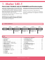
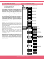
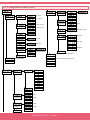
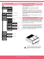
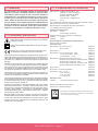
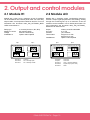
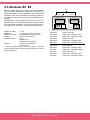
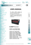
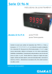
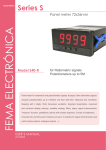
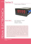
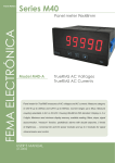
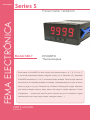
Series S
Panel Meters
FEMA ELECTRÓNICA
Panel meter 72x36mm
Model S40-T
Pt100/RTD
Thermocouples
Panel meter for Pt100/RTD (2 and 3 wires), and thermocouples J, K, T, E, S, R, N, C,
L and X with temperature display in degrees celsius (ºC) or fahrenheit (ºF). Selectable
Pt100/RTD resolution at 1º or 0.1º, and manual offset available. Thermocouple measure
with internal CJC selectable (enabled or disabled). Selectable behavior in case of sensor
break (‘to_high’ or ‘to_low’). Reduced size 72x36mm. Reading with 4 digits. Maximum
and minimum display memory, steps, alarms with single or double setpoints, 5 levels
of brightness, ... Universal AC and DC power modules and up to 2 modules for signal
retransmission and control (relay outputs, analogue outputs, ...).
USER’S Manual
(2264r05)
User’s Manual S40-T
1. Meter S40-T
Panel meter 72x36mm size for Pt100/RTD and Thermocouples
Panel meter for temperature signals, accepts Pt100/RTD with
2 and 3 wires, and thermocouples J, K, T, E, S, R, N, C, L and
X. Temperature display in degrees celsius (ºC) or fahrenheit
(ºF). Thermocouple cold junction compensation selectable.
Manual offset selectable. Selectable behavior for alarms in
case of sensor break (‘to_high’ or ‘to_low’).
Instrument with reduced 72x36mm size. Resolution 4 digits
with negative sign (“9999”/“-1999”).
Power options with universal AC and DC ranges, and space
for 2 additional control and/or signal retransmission modules.
Standard IP54 front protection. Optional green led.
Connections via plug-in screw terminals and configuration
via three front push-buttons. For application on industrial
environments.
Management for up to 2 alarms with 1 or 2 setpoints each
alarm, with hysteresis and delays. Provides memory for maximum and minimum, display on selectable steps, password
and selectable levels of brightness.
1.1 Order reference
Model
S40
-
T
Power
-
-
H
-H
-L
Option1
(85-265 Vac/dc)
(11-60 Vdc
and 24/48 Vac)
---R1 (1 relay)
-AO (Analogue Output)
-
(empty)
Option2
-
---R1 (1 relay)
-AO (Analogue Output)
-
(empty)
Others
---
-G
-
(green led)
(empty)
Index
1. Meter S40-T . . . . . . . . . . . . . . . . . . . . . . 2
1.1 Order reference . . . . . . . . . . . . . . . . . . 2
1.2 Front View . . . . . . . . . . . . . . . . . . . . . 3
1.3 Rear View . . . . . . . . . . . . . . . . . . . . . 3
1.4 Power Connections . . . . . . . . . . . . . . . . 3
1.5 Signal connections - Pt100 / RTD . . . . . . . . . 3
1.6 Signal connections - Thermocouples . . . . . . . 3
1.7 Technical data . . . . . . . . . . . . . . . . . . . 4
1.7 Technical data (cont.) . . . . . . . . . . . . . . . 4
1.8 Mechanical dimensions (mm) . . . . . . . . . . . 5
1.9 Operating the menus . . . . . . . . . . . . . . . 6
1.10 Configuration menu . . . . . . . . . . . . . . . 6
1.10 Configuration menu (cont.) . . . . . . . . . . . . 7
1.10.1 Input menu . . . . . . . . . . . . . . . . . . 8
1.10.2 Temperature configuration . . . . . . . . . . 8
1.10.3 Alarms . . . . . . . . . . . . . . . . . . . . 8
1.10.4 Display . . . . . . . . . . . . . . . . . . . . 8
1.10.5 Tools . . . . . . . . . . . . . . . . . . . . . 8
1.10.6 Menu OptX - Options . . . . . . . . . . . . . 9
1.11 Default factory configuration . . . . . . . . . . . 9
1.12 Messages and errors . . . . . . . . . . . . . . . 9
1.13 Information menu . . . . . . . . . . . . . . . . 10
1.13.1 Information menu . . . . . . . . . . . . . . 10
1.14 Accessing the instrument . . . . . . . . . . . . 10
1.15Warranty . . . . . . . . . . . . . . . . . . . . . 11
1.16 Installation precautions . . . . . . . . . . . . . .11
1.17 CE declaration of conformity . . . . . . . . . . .11
2. Output and control modules . . . . . . . . . . . . . 12
2.1 Module R1 . . . . . . . . . . . . . . . . . . . . 12
2.2 Module AO . . . . . . . . . . . . . . . . . . . . 12
2.3 Modules R2, R4 . . . . . . . . . . . . . . . . . 13
3. More options and accessories . . . . . . . . . . . . 14
3.1 Option G . . . . . . . . . . . . . . . . . . . . . 14
FEMA ELECTRÓNICA - Page 2
User’s Manual S40-T
1.2 Front View
1.5 Signal connections - Pt100 / RTD
Measure can be selected for 2 or 3 wire systems.
Alarms
1 2 3 4 5
Logo
Select input Pt100 2Wires in the
menu. Terminal 2 can be left unconnected.
RTD/Pt100
2 wires
Units
1 2 3 4 5
Button LE
Button UP
Button SQ
Access to
“Information Menu”
Access to
“Configuration Menu”
Select input Pt100 3Wires in the
menu
RTD/Pt100
3 wires
1.3 Rear View
Option1
Option2
1.6 Signal connections - Thermocouples
To configure, select the appropriate thermocouple type in the
configuration menu.
1 2 3 4 5
+
Signal
Power
1.4 Power Connections
6 7 8 9 0
~
+
~
-
Earth connection - Although a terminal is offered for earth connection, the
connection is optional. The instrument does not need this connection for
correct functioning nor for compliance with the security regulations.
Fuse - To comply with security regulation 61010-1, add to the power line
a protection fuse acting as disconnection element, easily accessible to the
operator and identified as a protection device.
Power “H” fuse 250mA time-lag
Power “L” fuse 400mA time-lag
FEMA ELECTRÓNICA - Page 3
Thermocouple
User’s Manual S40-T
1.7 Technical data
1.7 Technical data (cont.)
Digits4
Type
7 segments, red
Height
14 mm
Display maximum
9999
Display minimum
-1999
Decimal point
selectable 8.8.8.8.
Overrange 9999 flashing
Underrange
-1999 flashing
Signals accepted
Temperature scale
Display units
Power
Power “H”
85 to 265 Vac/dc
Power “L”
11 to 60 Vdc and 24/48Vac
Consumption<4W
Isolation
3500Veff for power “H”
2000Veff for power “L”
all levels tested for 60 seconds
Pt100/RTD and Thermocouples
ITS90
ºC or ºF, selectable
Thermocouple data
Thermocouples acceptedJ, K, T, E, S, R, N, C, L, X
(Thermocouple X is a linear 10uV/ºC signal)
Resolution1º
Ranges
see table 3
Max. error at 25ºC
see table 3
Offset drift see table 3
Span drift*
see table 3
*Note - span drift includes also the offset drift
CJC
automatic (“On”/“Off” selectable)
CJC accuracy
<1.0ºC
CJC thermal drift
<0.04º/ºC
On sensor break
“to_high” or “to_low”, selectable
Acquisitions
3 acquisitions / second
Pt100/RTD data
Sensors accepted
2 or 3 wire, selectable
Resolution
1º or 0.1º, selectable
Rangessee table 3
Alpha
Alpha385 or Alpha390, selectable
Max. error at 25ºC
see table 3
Offset drift
see table 3
Span drift *
see table 3
*Note - span drift includes also the offset drift
Cable compensation
up to 14 Ohm
Compensation accuracy <0.02ºC / Ohm
Acquisitions
4 acquisitions / second
Type
Configuration
3 frontal push buttons
Functions available
Steps Memory of maximum
Memory of minimum
Password
Double setpoints
Brightness control
yes, configurable
yes
yes
yes, configurable
yes
yes, 5 levels
Options
maximum 2
Mechanical
Mountingpanel
Connections
plug-in screw terminals
Weight
<150 grams
Housing materials ABS, polycarbonate, vergaflex
Front size
72x36mm
Panel cut-out
69x32.5mm
Deep from panel
98mm (including terminal)
Front protection Temperature Operation 0 to 50ºC
Temperature Storage
–20 to +70ºC
Warm-up 15 minutes
Max. error
Range ºC
IP54
Range ºF
at 25ºC*
Offset drift
Span drift*
*includes offset drift
800 / -200 ºC
<0.2ºC
1562 / -328 ºF
0.05º/ºC
0.10º/ºC
Thermocouple J
1200 / -200 ºC
<2ºC
2192 / -328 ºF
0.05º/ºC
0.20º/ºC
Thermocouple K
1372 / -200 ºC
<2ºC
2372 / -328 ºF
0.05º/ºC
0.20º/ºC
Thermocouple T
400 / -200 ºC
<2ºC
752 / -328 ºF
0.02º/ºC
0.02º/ºC
Thermocouple E
1000 / -200 ºC
<2ºC
1832 / -328 ºF
0.05º/ºC
0.20º/ºC
Thermocouple S
1768 / -50 ºC
<4ºC
2282 / -58 ºF
0.20º/ºC
0.20º/ºC
Thermocouple R
1600 / -50 ºC
<4ºC
2912 / -58 ºF
0.20º/ºC
0.20º/ºC
Thermocouple N
1300 / -200 ºC
<2ºC
2372 / -328 ºF
0.05º/ºC
0.20º/ºC
Thermocouple C
2320 /
0 ºC
<2ºC
4192 /
32 ºF
0.02º/ºC
0.02º/ºC
Thermocouple L
900 / -200 ºC
<2ºC
1652 / -328 ºF
0.05º/ºC
0.20º/ºC
Thermocouple X
4000 / -200 ºC
<2ºC
7232 / -328 ºF
0.02º/ºC
0.02º/ºC
Pt100/RTD
Table 3 - Thermocouple and PT100/RTD specifications
FEMA ELECTRÓNICA - Page 4
User’s Manual S40-T
1.8 Mechanical dimensions (mm)
36
72
80
8
Panel
cut-out
h
is
se
ct
io
n
b
la
n
k
69
T
32,5
18
FEMA ELECTRÓNICA - Page 5
User’s Manual S40-T
1.9 Operating the menus
1.10 Configuration menu
The instrument has two menus accessible to the user :
“Configuration Menu” (key SQ)
“Information Menu” (key UP)
Press SQ button to enter Configuration Menu
Pt100/RTD 2 wires
The “Configuration Menu” allows to change the configuration
of the instrument. Access to the “Configuration Menu” can be
password protected with the function “PASSWORD”. During
operation with the “Configuration Menu” the alarms are kept
“on-hold”. When leaving the “Configuration Menu” the instrument performs a restart, and new configuration is applied. On
restart of the instrument, also the control output modules are
restarted (relays, analogue outputs, ...).
Input
Pt100/RTD 3 wires
Thermocouple J
Thermocouple K
Thermocouple T
Thermocouple E
Thermocouple S
The “Information Menu” is for information only, and it does not
accept changes on the displayed information. To enter the “Information Menu” press the “UP” button. It is not affected by
the “PASSWORD” function. Leaving the “Information Menu”
returns to the measuring state of the instrument, without
restart of the unit.
Thermocouple R
Thermocouple N
Thermocouple C
Thermocouple L
Rollback - After 30 seconds without interaction from the
operator, the instrument leaves the menu and returns to the
previous working mode. In case of configuration menu, all
changes are discarded.
Button SQ - Selects the menu entry currently displayed.
When entering a numeric value (for example a setpoint value)
validates the value on display.
Button UP - Moves vertically on the menu entries. When
entering a numeric value (for example a setpoint value)
modifies the current digit by increasing its value up from 0 to
1, 2, 3, 4, 5, 6, 7, 8, 9.
Button LE - Leaves the current menu. Pressing LE several
times will leave all menus. When leaving all menus in the
configuration menu, changes will be saved . When entering
a numeric value (for example a setpoint value) it moves from
one digit to the next. Each digit value can then be modified
with the UP button.
Thermocouple X
Celsius
Temp. Config,
Degrees
Fahrenheit
1º Resolution
Pt100/RTD res..
Offset
0.1º Resolution
Offset counts
to add
Thermoc. CJC
Reading to high
On break
Alpha
FEMA ELECTRÓNICA - Page 6
Reading to low
User’s Manual S40-T
1.10 Configuration menu (cont.)
Alarms
Tools
Password
Select password
Al. active
Alarm1
Active
Al. inactive
Factory
configuration
Alarm as max.
Alarm type
Apply
Alarm as min.
Firmware version
Version
Setpoint
Minimum
Brightness
Counts
Hysteresis
Standard
Seconds
Delay
Maximum
Setpoint2
Second setpoint
Menu for optional module at Opt1
Option1
Menu for Alarm2
Menu for optional module at Opt2
Option2
Display
Steps
Counts for step
Value
Memory of
maximum
Reset
Value
Memory of
minimum
Reset
FEMA ELECTRÓNICA - Page 7
User’s Manual S40-T
1.10.1 Input menu
The input menu selects the input signal range. Options available are Pt100/RTD 2 or 3 wires, and thermocouples J, K, T,
E, S, R, N, C, L and X.
Note - Thermocouple X is a linear signal at 10uV/ºC.
1.10.2 Temperature configuration
The temperature configuration menu sets the function parameters for Pt100/RTD and thermocouple sensors.
Delay (DEL) - Value from “0.0” to “99.9” seconds. Delay to be
applied to the relay activation and deactivation. Relays are
activated and deactivated X seconds after the activation /
deactivation of the alarm. The delay affects only to the relays.
The delay does not affect to the front leds.
Setpoint2 (SET2) - Value from “-1999” to “9999”. Second
setpoint. The second setpoint allows for the creation of activation windows. If the alarm is configured as maximum with
setpoint 1000 and setpoint2 is configured at 1500, the alarm
will be activated between 1000 and 1500 and the alarm will
be deactivated when display is <1000 and >1500. Setpoint2
is affected on the same way as the setpoint with hysteresis
and delays.
Degrees (DEG) - Value “ºC/ºF”. Select the temperature to be
displayed in celsius or fahrenheit degrees.
Pt100/RTD resolution (P.RES) - Value “1º/0.1º”. Resolution
for the Pt100/RTD. Select to display with degree or tenth of
degree resolution.
Offset (OFFS) - Value from “-9999” to “9999” counts. Offset
to be added to the reading. Both for Pt100/RTD and thermocouples.
Thermocouple Cold Junction Compensation (T.CJC) Value “On/Off”. Select “On” for automatic CJC compensation
in the instrument. Select “Off” to disable the CJC compensation.
On break (ON.BK) - Value “to_h/to_l”. Select “To L” to make
the reading go to minimum, in case of probe broken. Select
“To H” to make the reading go to maximum in case of probe
broken.
Alpha (ALPH) - Value “385/390”. Select “385” or “390” according to your Pt100/RTD sensor.
1.10.3 Alarms
The instrument can manage up to 2 alarms. These alarms
control optional relays R1 (see section 2.1) which can be installed at slots Opt1 and Opt2. More alarms can be achieved
by installing special control modules R2 and R4. Configuration
menus for special modules are not listed in this document.
Active (ACT) - Value “ON/OFF”. Defines if the instrument
has to manage this alarm or not. Select “OFF” for alarm not
managed.
Type (TYPE) - Value “MAX/MIN”. Defines the behavior of the
alarm as maximum or minimum alarm. The alarms configured
as maximum are activated when the display value is equal or
higher than the setpoint. The alarms configured as maximum
are deactivated when the display is lower than the setpoint.
The alarms configured as minimum have the inverse behavior.
Setpoint (SET) - Value from “9999” to “-1999”. Alarm set point.
1.10.4 Display
Functions on this menu allow for configuration of the visualization.
Steps (STEP) - Display changes on predefined steps. Values
are 1, 2, 5, 10, 20 and 50. The display is made in steps of X
counts. For example, select a step of 20 will make the display
to change in steps of 20 (1420, 1440, 1460, ...).
Maximum (MAX) - Memory of maximum display. Indicates
the maximum value of display since the last reset of the
memory. Memory is reset on the following cases : manual
reset from the Configuration Menu (Maximum), change on
the input signal (Input), modification on the scaling (Scaling),
change on the decimal point (dP), modification of the linearization segments, or instrument power-down.
Minimum (MIN) - Memory of minimum display. Indicates the
minimum value of display since the last reset of the memory.
Memory is reset on the following cases : manual reset from
the Configuration Menu (minimum), change on the input
signal (Input), modification on the scaling (Scaling), change
on the decimal point (dP), modification of the linearization
segments, or instrument power-down.
1.10.5 Tools
Password (PASS) - Select a number to act as password. This
password will be requested when entering the Configuration
Menu. To deactivate the password select “Off”.
Factory Settings (FACT) - Factory default configuration.
Select “yES” to activate the factory default configuration.
Version (VER) - Firmware version installed.
Light (LIGH) - Luminosity. Select between 5 predefined
levels of luminosity.
Hysteresis (HYST) - Value from “0” to “9999”. Points of hysteresis. The hysteresis applies on the deactivation of the alarm.
FEMA ELECTRÓNICA - Page 8
User’s Manual S40-T
1.10.6 Menu OptX - Options
Menu options OPT1 and OPT2 give access to the configuration menus of the options installed at slots Opt1, Opt2 and
Opt3. This menu depends on the installed option. If there is
no option installed the instrument shows “NONE”. Control
modules R1 are controlled from the standard alarm menu
(see section 1.12.7).
1.11 Default factory configuration
Sensor
Pt100 2Wire
DegreesºC
Resolution0.1º
Offset0
On Break
To high
Alpha385
Alarms 1 and 2
Active
Off (not managed)
Type
maximum
Setpoint
1000
Hysteresis
0 counts
Delay
0.0 seconds
Setpoint2 Off
Display
Steps
Off
Memory of maximum -1999
Memory of minimum 9999
Tools
Password
Off
Brightness
3
1.12 Messages and errors
When the instrument detects that the displayed value does
not correspond to the input value, the display will flash and
alternate with a message.
“h.udr” Hardware underrange. The thermocouple signal is
lower than minimum readable signal (-30mV).
“h.oVr” Hardware overrange. The thermocouple signal is
higher than maximum readable signal (80mV).
“d.udr” Display underrange. The Pt100/RTD is shortcircuited.
“hoLd” The instrument is showing the value present when
the hold function was activated. Hold function is active.
“Min” The instrument displays the minimum displayed
value in memory. The minimum visualization is active.
“MAX” The instrument displays the maximum displayed
value in memory. The maximum visualization is active.
“brk”
The instrument displays “brk” with either “9999” or
“-1999” when : 1) resistance measured is higher than 390
Ohms (higher than 850ºC for PT100/RTD measure), or 2) in
case the third wire ohm is higher than 15 Ohm, or 3) thermocouple measure is open circuit.
“Err.1”
Password incorrect.
“Err.2” The instrument has detected an installed option but
was unable to communicate.
“E.101” Option is installed but the type can not be recognized.
FEMA ELECTRÓNICA - Page 9
User’s Manual S40-T
1.13 Information menu
1.13.1 Information menu
Configuration (Conf) - Information on the configured input
sensor and the degrees selected.
Press UP button to enter Information Menu
Maximum (MAX) - Value of the maximum display.
Configuration
Sensor type
Minimum (MIn) - Value of the minimum display.
ºC or ºF
Memory of maximum
Maximum
OptionX (OptX) - Type of module installed. If there is no
module shows “nonE”.
Memory of minimum
Minimum
1.14 Accessing the instrument
“On / Off”
Alarm1
“Max” / “Min”
Setpoint
Counts
Hysteresis
Seconds
Delay
Second
setpoint
Setpoint2
AlarmX (ALX) - Configuration of alarm X. The sequence of
information shows if the alarm is being managed (“On/Off”),
the alarm type (“Max/Min”), the setpoint, the hysteresis value,
the activation delay and the value of setpoint2 (“Off” or the
setpoint2 value).
You may need to access the inside of the instrument to insert
additional modules. Use a flat screwdriver to unlock the upper
clips marked with “A”. Then unlock the lower clips marked
with “B” and move out the front filter. Let the inside of the
instrument slide out of the housing.
To reinsert the instrument make sure that all modules are
correctly connected to the pins on the display module. Place
all the set into the housing, assuring that the modules correctly fit into the internal guiding slides of the housing. Once
introduced, place again the front filter by clipping first the
upper clips “A” and then the lower clips “B”.
See menu for Alarm1
Option installed
Option1
A
Option installed
Option2
B
Risk of electric shock. Removing the front cover will
grant access to the internal circuits. Disconnect the
input signal to prevent electric shock to the operator.
Operation must be performed by qualified personnel
only.
FEMA ELECTRÓNICA - Page 10
User’s Manual S40-T
1.15Warranty
1.17 CE declaration of conformity
All instruments are warranted against all manufacturing
defects for a period of 24 MONTHS from the shipment date.
This warranty does not apply in case of misuse, accident or
manipulation by non-authorized personnel. In case of malfunction get in contact with your local provider to arrange for
repair. Within the warranty period and after examination by
the manufacturer, the unit will be repaired or substituted when
found to be defective. The scope of this warranty is limited to
the repair cost of the instrument, not being the manufacturer
eligible for responsibility on additional damages or costs. .
1.16 Installation precautions
Risk of electrical shock. Instrument terminals can be connected
to dangerous voltage.
Instrument protected with double isolation. No earth connection
required.
Instrument is in conformity with CE rules and regulations. See
“CE Declaration of Conformity” further in this document.
This instrument has been designed and verified according to the 61010-1
CE security regulation, and is designed for applications on industrial environments. See the “CE Declaration of Conformity” further in this document for
information on the category of measure and the degree of pollution levels
that apply.
Installation of this instrument must be performed by qualified personnel
only. This manual contains the appropriate information for the installation.
Using the instrument in ways not specified by the manufacturer may lead
to a reduction on the specified protection level. Disconnect the instrument
from power before starting any maintenance and / or installation action.
The instrument does not have a general switch and will start operation as
soon as power is connected. The instrument does not have protection fuse,
the fuse must be added during installation.
The instrument is designed to be panel mounted. An appropriate ventilation
of the instrument must be assured. Do not expose the instrument to excess
of humidity. Maintain clean by using a humid rag and do NOT use abrasive
products such as alcohols, solvents, etc.
General recommendations for electrical installations apply, and for proper
functionality we recommend : if possible, install the instrument far from
electrical noise or magnetic field generators such as power relays, electrical motors, speed variators, ... If possible, do not install along the same
conduits power cables (power, motor controllers, electrovalves, ...) together
with signal and/or control cables.
Before proceeding to the power connection, verify that the voltage level
available matches the power levels indicated in the label on the instrument.
Manufacturer
FEMA ELECTRÓNICA, S.A.
Altimira 14 - Pol. Ind. Santiga
E08210 - Barberà del Vallès
BARCELONA - SPAIN
www.fema.es - [email protected]
Products S40-T
The manufacturer declares that the instruments indicated comply
with the directives and rules indicated below.
Electromagnetic compatibility directive 2004/108/CE
Low voltage directive 2006/95/CE
Security rules EN-61010-1
Instrument Fixed
Permanently connected
Pollution degree 1 and 2 (without condensation)
Isolation Double
CategoryCAT-II
Electromagnetic compatibility rules EN-61326-1
EM environmentIndustrial
Immunity levels
EN-61000-4-2 By contact ±4 KV
By air ±8 KV
Criteria B
Criteria B
EN-61000-4-3 Criteria A
EN-61000-4-4 On AC power lines : ±2 KV
On DC power lines : ±2 KV
On signal lines : ±1 KV
Criteria B
Criteria B
Criteria B
EN-61000-4-5
Between AC power lines ±1 KV
Criteria B
Between AC power lines and earth ±2 KV Criteria B
Between DC power lines ±1 KV
Criteria B
Between DC power lines and earth ±2 KV Criteria B
Between signal lines and earth ±1 KV
Criteria B
EN-61000-4-6
Criteria A
EN-61000-4-8 30 A/m at 50/60 Hz
Criteria A
EN-61000-4-110 % 1 cycle
40 % 10 cycles
70 % 25 cycles
0 % 250 cycles
Criteria A
Criteria A
Criteria B
Criteria B
Emission levels
CISPR 11 Instrument Class A, Group 1 Criteria A
Barberà del Vallès November 2014
Daniel Juncà - Quality Manager
According to directive 2012/19/EU, electronic equipment must be recycled in a selective and controlled
way at the end of its useful life.
In case of fire, disconnect the instrument from the power line, fire alarm
according to local rules, disconnect the air conditioning, attack fire with
carbonic snow, never with water.
FEMA ELECTRÓNICA - Page 11
User’s Manual S40-T
2. Output and control modules
2.1 Module R1
2.2 Module AO
Module with 1 relay. Up to a maximum of two R1 modules
can be installed in one S Series panel meter. For more relay
output needs, check special modules R2 and R4. For more
information see document 2657_S40_OPTIONAL_MODULES at www.fema.es
Module with 1 analogue output. Configurable 4/20mA or
0/10Vdc. Output signal proportional to the reading. Scaling
through the frontal keypad. Up to a maximum of two AO
modules can be installed in one S Series panel meter. For
more information see document 2657_S40_OPTIONAL_
MODULES at www.fema.es
Relay type
Maximum current
Voltage
Installable at
Output
Accuracy
Isolated
Thermal drift
Installable at
3 contacts (Common, NC, NO)
8A (resistive load)
250 Vac continuously
Option1 and/or Option2
Opt 1
A
B
Opt 1
Opt 2
C
Signal
Terminal A
Terminal B
Terminal C
A
B
4/20mA, 0/10Vdc selectable
0.1% FS
yes, 1000Vdc
50 ppm/ºC for Vdc
60 ppm/ºC for mA
Option1 and/or Option2
C
MV A
Power
Signal
Common
NO - Normally Open
NC - Normally Closed
B
Opt 2
C
MV A
B
C
Power
Jumper M
Jumper V
mode mA
mode Vdc
Terminal A
Terminal B
Terminal C
Vexc (+13.8Vdc @25mA)
Signal output (mA or Vdc)
GND
FEMA ELECTRÓNICA - Page 12
User’s Manual S40-T
2.3 Modules R2, R4
Special modules with 2 and 4 relays. Use special modules
R2 or R4 when standard R1 modules do not provide required functionality for your application. Only one special
module R2 or R4 can be installed in an S Series panel meter. Special modules R2 and R4 are not compatible with R1
modules.
Configuration is done through the OPTx entry of the configuration menu. Functionality for R2 and R4 modules differs
from standard R1 modules. For more information see document 2657_S40_OPTIONAL_MODULES at www.fema.es
R4
R2
Opt 1
ABCDEF
Signal
Number of relays
2, or 4
Relay type
3 contacts (Common, NO, NC)
Maximum current
6A (resistive load) (each relay)
Voltage*
250 Vac continuously
Installable at slot
Opt.1.
R2 fills OPT1
R4 fills OPT1 and OPT2
Terminal
Plug-in screw terminals
pitch 3.81mm
* Terminals approved for 300V (according to UL1059,
groups B and D) and 160V (according to VDE in CAT-III and
pollution degree 3).
Opt 2
G H I J K L
Power
Terminal A
Terminal B
Terminal C
Terminal D
Terminal E
Terminal F
Relay1 Common
Relay1 NO - Normally Open
Relay1 NC - Normally Closed
Relay2 Common
Relay2 NO - Normally Open
Relay2 NC - Normally Closed
Terminal G
Terminal H
Terminal I
Terminal J
Terminal K
Terminal L
Relay3 Común
Relay3 NO - Normally Open
Relay3 NC - Normally Closed
Relay4 Common
Relay4 NO - Normally Open
Relay4 NC - Normally Closed
FEMA ELECTRÓNICA - Page 13
User’s Manual S40-T
3. More options and accessories
3.1 Option G
Green led option.
Green led
FEMA ELECTRÓNICA - Page 14
T
H
IS
P
A
G
E
B
L
A
N
K
User’s Manual S40-T
FEMA ELECTRÓNICA - Page 15
other products
Panel Meters
Standard 96x48mm
Panel Meters
Small 72x36mm
Panel Meters
Miniature 48x24mm
Large Displays
60&100mm digit
Signal Converters
& Isolators
Bar Meters
www.fema.es
ELECTRONIC INSTRUMENTATION FOR INDUSTRY
FEMA ELECTRÓNICA, S.A.
Altimira 14 - Pol. Ind. Santiga
E08210 Barberà del Vallès
BARCELONA - SPAIN
Tel. (+34) 93.729.6004- www.fema.es
Fax (+34) 93.729.6003- [email protected]